| 1Site Map |
1-i INTRODUCTION |
All toolbar buttons
everywhere are functional and will take you to where they are discussed. |
| Items listed in this column include the hyperlinks associated with the toolbars,
listed in the right column. As this eGuide is updated for ADT 2005, information will be
posted about what has been updated. |
Toolbars listed in this column come from Architectural Desktop 3.3. They
were not included in the 2005 release but you can migrate them manually or download our
PowerSTRIP R5.0 Menu. |
| |
INTRODUCTION
Site Map, Basic
Interface Concepts, Options and AEC Settings, Getting StartedStatus:
0% Complete |
 |
 |
PART1
AEC Display - Setup. Anatomy of Architectural Desktop
objects; what controls their behavior and appearance. Template Files. Drawing Setup. Changing Display
Configurations. Display Manager Window.
Object Styles. Style Manager Window.
Display Properties.Status:
0% Complete - more detailed information will be added
over time for Style Properties as they apply to all objects. |
 |
PART2
Layer Management. Layer
Manager and Layer Keys. Layer Standard Properties. Layer Key
Styles and Overrides. Layer Snapshots. Layer Filters and
Groups. Remapping Object Layers.
Status:
95% Complete - more will be added for
Layer Standards and Key Styles. |
 |
|
PART2.5
Projects.
Projects Overview. Project Browser. Project Navigator.
Constructs, Elements, Views and Sheets. Project Defaults.
Project Template. Annotation. |
|
 |
PART3
Walls. Importing
Wall Styles. Copying Wall Styles. Adding and Justifying Walls. Wall
Properties. Convert to Walls. Wall Priorities and Cleanup Groups. Wall
Style Properties. Wall Problems.Status:
0% Complete. |
 |
PART4
Wall Tools. Wall Modifiers. Wall
Endcaps. Merge Walls. Roof and Floor Lines. Interference conditions.
Sweeping. Wall Body Modifiers. Wall Dimensions.Status:
0% Complete |
 |
PART5
Curtain Walls. Importing Curtain Wall Styles.
Adding Curtain Walls. Converting Walls, Linework and Layout Grids to Curtain
Walls. Modifying Curtain Walls. Editing Curtain Wall in-place. Working with
Curtain Wall Styles. Curtain Wall Units. This is a huge subject - more will be
coming.Status:
0% Complete |
 |
PART6
Doors, Windows, Openings
and Door/Window Assemblies. Loading Door, Window and Window Assembly Styles. Working with
these objects and controlling their behavior. How to display unique features, like
sills and thresholds. How to Profile your own Door, Window or Opening to create your
own Style. All about Window Assemblies.Status:
0% Complete |
 |
PART7
Stairs and Railings. Loading Stair and
Railing Styles. Adding Stairs. Modifying Stairs. Working with Stair Styles.
Adding Railings. Modifying Railings. Converting to Railings.
Anchoring Railings. Working With Railing Styles.Status:
0%
Complete |
 |
PART8
Roofs and Roof Slabs. Adding Roofs.
Converting to Roofs. Modifying Roofs. Display Properties.
Customizing and Tricks - Arched Roofs. Loading Roof Slab Styles. Adding Roof
Slabs. Modifying Roof Slabs. Converting to Roof Slabs. Roof Slab
Styles. Roof Slab Edge Styles.Status:
0% Complete |
 |
PART9
Roof Slab Tools. Roof Slab Trim,
Extend, Miter and Cut. Roof Slab Vertexes. Holes, Add, Subtract and Dormers.
Customizing and Tricks - California Framing and Barrel Vaults.Status:
0% Complete |
 |
PART10
Slabs. Slab Tools. Loading Slab
Styles. Adding Slabs. Modifying Slabs. Converting to Slabs. Slab
Styles. Slab Edge Styles. Slab Trim, Extend, Miter and Cut. Slab
Vertexes. Holes, Add and Subtract. Customizing and Tricks - Shower Bases.Status:
0% Complete |
 |
 |
PART11
Spaces. Overview. Adding Spaces.
Modifying Spaces. Joining, Dividing, and Swapping Spaces. Interference.
Generating Spaces from Walls and Linework. Space Styles. Display
Properties. Space Database Information. Converting to Space Boundaries
and Walls. Customizing and Tricks.Status:
100% Complete |
 |
PART12
Grids. Adding Column Grids. Modifying
Column Grids - controlling spacing and editing with Grips. Clipping Column Grids.
Display Properties of Column Grids. Annotating Column Grids and controlling
numbering. Adding Ceiling Grids. Modifying Ceiling Grids - controlling
spacing. Clipping Ceiling Grids. Display Properties of Ceiling Grids.
Customizing - adding ceiling fixtures to Ceiling Grids.Status:
0%
Complete |
 |
PART13
Structural Members. Loading Structural Member
Styles. Adding Columns, Braces and Beams. Modifying Members. Trim Planes.
Converting to Members. Structural Member Styles. Display Properties.
Structural Member Catalog. Structural Member Wizard. Custom
Profiles.Status:
0% Complete |
 |
PART14
Elevations. Overview and Xref discussion.
Adding Elevation Lines. Modifying Elevation Lines. Elevation Line Display
Props. Creating 2D and 3D Elevations. Modifying 2D and 3D Elevations.
Working with 2D and 3D Elevation Display Properties for Color and lineweight control.
Materials for Elevations.Status:
0% Complete. |
 |
PART15
Sections and Live Sections. Overview
and Xref discussion. Adding Section Lines. Modifying Section Lines. Section
Line Display Props. Creating 2D, 3D and Live Sections Modifying 2D, 3D and
Live Sections. Working with 2D and 3D Section Display Properties for Color and
lineweight control.Status:
0% Complete |
 |
 |
 |
PART16
Design Content. Overview of Multi-view
Blocks. Examples of Design Content types ( this will be a work in progress ).
Modifying Design Content objects. Changing Text in Design Content Blocks.
Changing or adding View Directions ( often needed for such things as Reflected Ceiling
Plans ). This Part is not complete. Note: There are actually four
toolbar options for this topic but the content is the same.Status:
0%
Complete |
 |
 |
PART17
Documentation Content. Adding Documentation
Content Symbols. Modifying Documentation Content Symbols.
Understanding the Structure of these Symbols to Create your own from scratch
or from existing Symbols. AEC Content Wizard.Status:
100% Complete |
 |
 |
 |
PART18
Schedules. Drawing Scale for Tag and Schedule
sizing. Anatomy of a Schedule. Adding Tags. Adding Schedule Data.
Renumbering and Modifying Tags and Schedule Data. Property Set Definition
Styles. Schedule Data Format Styles. Schedule Table Styles. Exporting
Schedules.Status:
0% Complete |
 |
 |
PART19
Dimensions and Dimension Labels. AEC
Dimension Overview. Adding AEC Dimensions. Manually Adding AEC Dimensions,
Objects and Points. Removing Attached Objects and Points. Converting AutoCAD
Dimensions to AEC Dimensions and Exploding AEC Dimensions to get AutoCAD Dimensions.
AEC Dimension Styles. Match Properties. Activating Text Grips.
AEC Wizard. Dimension Labels. Customizing and Tricks.Status:
100% Complete |
 |
PART20
Areas. Adding Area objects. Create Area
object from other objects. Modifying Area objects. Area object Properties.
Join, Subtract and Intersect Area objects. Edit Area object Vertices. Trim
and Divide Area objects. Convert Area objects to Plines. Area Styles. Area
Name Definitions. Area Calculation Modifiers. Area Evaluations ( Reports ).Status:
100% Complete |
 |
PART21
Area Groups. Adding Area Groups.
Modifying Area Groups. Using Grips on Area Groups. Attaching and Detaching
Areas to/from Area Groups. Converting Area Group contents to Plines. Creating Area
Group Styles. Creating Area Group Template files and Creating Area Groups from these
Template files.Status:
100% Complete |
 |
 |
PART22
Layout Tools. Working with the Layout Curve,
Layout Grid and Volume. Anchoring to these tools. Modifying
Layout tools. Display Properties.Status:
0% Complete |
 |
PART23
Anchors. Working with the Curve Anchor.
Working with the Leader Anchor. Working with the Node Anchor.
Working with the Cell Anchor. Working with the Volume Anchor.
Working with the Object Anchor. Display
Properties. Status:
100% Complete |
 |
PART24
AEC Polygons. Adding AEC Polygons.
Modifying AEC Polygons. AEC Polygon Styles. Converting Polyline base Polygons
into AEC Polygons.Status:
0% Complete |
 |
PART25
AEC Blocks - Profiles. Multi-View Block
concept. Adding Multi-View Blocks. Modifying Multi-View Blocks. Multi-View
Block Definition Styles. Creating Multi-View Blocks. Adding Mask Blocks.
Modifying Mask Blocks. Mask Block Definition Styles. Create AEC Content
Wizard. Profiles. Customizing and Tricks. Status:
0%
Complete |
 |
PART26
Utilities. Adding Notes to objects.
Object Viewer. Quick Slice. Referencing Objects. Create Hidden Line
Removal. AEC Object Explode. Customizing and Tricks.Status:
0% Complete |
 |
 |
PART X
- Appendix. This is where you will find extra items that were
added late, are part of every topic or downloadable examples. Tool
Palettes. Material Definition Styles. Material Tools.
Render Materials and VIZ Render. Display Settings on the Options
dialog. |
|
| 2Basic Interface Concepts |
2-i INTRODUCTION |
| Hey, where
did all of my stuff go? Autodesk®
AutoCAD® 2005 and Autodesk® Architectural Desktop 2005 (referred to in
this guide as ADT 5 or ADT 2005) now meet Microsoft® Compliance and Certification requirements for
Windows® 2000 and XP operating systems. What this means to previous users of
AutoCAD and Architectural Desktop is that software data is no longer stored in one
convenient folder but spread out a bit. You will still find the primary application
data under Program Files\Autodesk Architectural Desktop 2005 but for a
lot of the items that are likely to be unique between users, you will find them under the Documents
and Settings folder as illustrated to the right. The primary reason I have
decided to comment on this spaghetti nest of folders is that you may need to do some GUI
and file location adjustments to ADT 5 in order to feel more comfortable with this
upgrade. The menu files that you may want to work with, for example, are now stored under Documents
and Settings\ [YourLoginName] \Application Data\Autodesk\ADT
2005\enu\Support. If you do not find the items you are looking for
under this path, your IT Manager may have set your system up for "roaming"
accounts and thus this information resides somewhere on an office Server ( don't ask me
where, it's different for every office ).
 If you don't tinker with software and just run it
as is, out of the box, then you may still want to become familiar with these path
locations because they apply to many things inside Architectural Desktop. The most
important location path to know is where ADT keeps all of your Content files ( all those
Multi-View Blocks and Object Styles ). By default, you will find the Content files
at \Documents and Settings\All Users\Application Data\Autodesk\ADT 2005\enu\AEC Content and after this folder you can
choose between Imperial or Metric Content if you happen to have installed both. If you don't tinker with software and just run it
as is, out of the box, then you may still want to become familiar with these path
locations because they apply to many things inside Architectural Desktop. The most
important location path to know is where ADT keeps all of your Content files ( all those
Multi-View Blocks and Object Styles ). By default, you will find the Content files
at \Documents and Settings\All Users\Application Data\Autodesk\ADT 2005\enu\AEC Content and after this folder you can
choose between Imperial or Metric Content if you happen to have installed both.
If you do tinker with software, these locations, paths and
folders can be moved around and relocated to a central server. The primary issue
with relocating this information to a central server is network speed and getting all of
the paths set within ADT to find this information. |
Default Folder Structure
Primary Program Application Files
C:\Program Files\Autodesk Architectural Desktop 2005\
Primary Program Application PC System
Data Files
C:\Documents and Settings\All Users\Application Data\Autodesk\ADT 2005\enu
Primary Program Application User Data
Files
C:\Documents and Settings\[User Login Name]\Application Data\Autodesk\ADT 2005\enu |
| Adjusting to the New Interface for AutoCAD and ADT Users When ADT
5 has been installed and launched for the first time,
previous users of AutoCAD and ADT may find the new GUI interface surprisingly light.
For new users, the process of selecting objects and right-clicking on the mouse, appears
to be your best option for learning about the commands that are now no longer accessible
through pull-down menus or toolbar buttons. For those migrating from ADT 3 - 3.3,
ARCHIdigm has created a toolbar and menu system called the "PowerSTRIP" that you can
download, install and use as a separate menu that has all of the old ADT 3.3 toolbar
buttons. There are also other options that you can employ to add more traditional
menu/command items to the GUI interface:
1) To get the AutoCAD pull-down and
toolbar menus back as they have been for years, you can use the MenuLoad
command and find the ACAD.mnc file under the Support folder
- see comments above for "Hey, where
did all of my stuff go?"
Once you have located the ACAD.mnc file and loaded it, you
will have to use the Menu Bar tab of the Menu Customization
dialog box to Insert Menu Items
from the ACAD Menu Group over to the current Menu Bar.
There are only a few pull-down menus to worry about, such as Draw,
Modify and Dimensions. If you don't need these
pull-down menus, then at least you will now have access to the Toolbars including the
slick new Style toolbar which has a Text Style pull-down ( I've asked for this for many
years now ).
2) To get some of the older ADT 3 - 3.3
pull-down menus back, you can use the Window pull-down menu to access a
cascading menu called "Pulldowns". On this menu you
should find the old ADT "Design" and "Document"
pull-down menus. It would have been great if they had just expanded the list to
include all of the old menus and included the Express
menu item as well ( even if it reminded you to load it first ).
3) The old Layer Manager
dialog box is now gone for good. AutoCAD 2005 and ADT 2005
users now share the same single Layer Manager dialog but ADT 2005 users have
extra tools that apply to Layer Standards, Keys and so forth. This
tool is noticeably sluggish, especially upon first activation, and many
users have complained bitterly to Autodesk. If you visit the Autodesk
Support area and check for Patches and Fixes, you should find a "Fix" for
ADT 2005 Users that will make this dialog run slightly faster. The
best way to speed up performance is to remove as many unused items in it;
such as filters and groups.
 4)
If your computer feels sluggish with all the glossy new graphics they added to ADT
5, you
can take a few steps to speed it up. One of the biggest changes you can make is to turn off
the Materials Display when using Shaded Modes. You will find this
setting on the System tab of the Options dialog box -
see Properties button to Render options. Uncheck Render
options. Though this is a really neat feature that has been available for a
few years now, it puts a bit of a strain on older systems with poor graphics cards.
The new Palettes add a graphic strain to computer video cards as well, particularly
if they have been set to be transparent. To turn Off Transparency for the Palettes,
right-click over the Title Bar and look for the "Transparency..." pop-up menu
option. Keeping the Properties Palette
active at all times also tends to create a lag effect as it continually updates the data
and options you have for objects being drawn. 4)
If your computer feels sluggish with all the glossy new graphics they added to ADT
5, you
can take a few steps to speed it up. One of the biggest changes you can make is to turn off
the Materials Display when using Shaded Modes. You will find this
setting on the System tab of the Options dialog box -
see Properties button to Render options. Uncheck Render
options. Though this is a really neat feature that has been available for a
few years now, it puts a bit of a strain on older systems with poor graphics cards.
The new Palettes add a graphic strain to computer video cards as well, particularly
if they have been set to be transparent. To turn Off Transparency for the Palettes,
right-click over the Title Bar and look for the "Transparency..." pop-up menu
option. Keeping the Properties Palette
active at all times also tends to create a lag effect as it continually updates the data
and options you have for objects being drawn.
Note: If you still have ADT 3.3 around,
you can copy the AecArchX.mnu and .dll files over to ADT 5 and use the MenuLoad command to
bring the old toolbars over. You could even bring in the old pull-down menus too. |
|
| ADT Pull-down Menu Layout ADT
5 has had a major menu renovation job done since ADT 3.3 and in
the default installation state, you will not find any pull-down menus that are
specifically for ADT. What you will find is that many ADT tools and commands have
been integrated into pull-downs that have the same name in AutoCAD 2004: Format,
Insert and Window for example. Of this set, you
will find most of the ADT specific commands and tools listed under the Format
pull-down menu.
Illustrated to the right I show some other pull-down menus
that you can either load or toggle On for Architectural Desktop. The Details
pull-down menu is for the newly integrated AEC Details tool that had to be run separately
in the past; this is an optional item that you can choose to install when first installing
ADT. The Design, Document, CAD Manager
and 3D Solids pull-down menus are all menus that you can toggle On or Off
via the Windows > Pulldowns > cascading menu.
Even though you can activate some of the older pull-down
menus, as discussed above, they are not the same as their predecessors and are instead,
rather light on the command offerings. For those who use ADT as a regular AutoCAD
drafting tool as well, even those pull-down menus have been removed from the default
installation state of ADT and you many have to load those just to get access to some of
the cool new features offered in AutoCAD 2005, such as the Text Styles drop-down list.
The reason ADT 5 is so light on pull-down menus and
toolbars is that a massive rewrite has transpired to make the interface and command access
more "user friendly". That remains to be seen but however you feel about
the new GUI interface and command access, there's really no way to avoid it. The new
Tool Palettes, with the slick 32 bit fully rendered 3D icons contains
more than pretty pictures of objects; it actually has embedded information about those
objects that you cannot set through the Object Styles anymore. This information,
found via the Tool Palettes icon Properties, usually contains default settings for
dimensions, heights and similar values to be discussed throughout this guide.
Due to this restructuring and rewrite, it appears that a
lot of commands and command options have fallen out of easy reach and special care has to
be taken now to find them. Though a good deal of commands and command options have
been integrated into the object specific pop-up menus, I continue to find holes where
things were left out. One particular example is the command that allows you to
Convert Plines to Walls. Many users employ this technique because it is a natural
way to outline a building envelope; you would expect that by selecting a Pline and
right-clicking that you would see the option to Convert to Wall. There is in fact an
option to Convert to Mass Elements and Profiles but not Walls. Therefore, I suggest
that new and older users alike read the command line options while using this program so
you don't miss out on great tools. When you type "wall", for example, this
is the list you will see: [Add/ COnvert/ Properties/ Styles/ CLeanup groups/
Dimension/Interference/ Reverse]. |
 The Design pull-down menu focuses on the production
end of the design process with access to the primary ADT design objects such as Walls,
Doors, Windows, Beams, Slabs, Roofs, Stairs and more. This menu also provides access to
Properties and Style tools for these objects but most of the editing can be done in-place
or via the Properties Palette.
The Document menu offers
access to some very basic documentation tools such as Areas, Schedules, AEC Dimensions,
Sections and Elevations and a few more. For documentation symbols and object tags,
you have to use the DesignCenter or the Tool Palettes. |
| Express Tools -
They Are Back!
If you insert Disk 1 of 2 for the Architectural Desktop
installation, you can now click your way down through the Support folder to find
the Express folder where the full set, Volumes 1-9, are ready to be
installed. These, by the way, can only be installed for AutoCAD 2005 and other 2005
Flavors; i.e., you cannot install them for older releases.
If you are new to the Express Tools, illustrated to the
right, you are in for a major treat. The Express Tools are a compilation of unique
routines that were never an integrated part of AutoCAD but usually worked extremely well.
Most of these tools were written and developed by other AutoCAD users and
programmers and that was why they were never fully integrated ( never fully supported,
that is ).
Of the set, I think it fair to say that the Layer tools are
the most widely used and valued. My personal favorite is the Layer Freeze (LayFrz)
command that also works inside Viewports by only Freezing objects selected in the current
Viewport. |
 |
| ADT Toolbar Access Activating
Toolbars in ADT can be accomplished through several different techniques.
Illustrated to the right I show two methods that provide access to all toolbars no matter
what menu they may be a part of. Of these two methods, my personal favorite is to right-click
over any unused space adjacent to existing docked toolbars. You can
usually find unused toolbar space along the top of ADT under the pull-down menus and/or
along the sides if you have toolbars docked there. If you right-click over a
particular button on a toolbar you will only get access to the toolbars within that same
menu.
The other method for acquiring access to all of the
toolbars in ADT is to use the Customize menu option/command. The
Customize dialog can be invoked from the Tools pull-down menu or by typing Customize on
the command line.On the Customize dialog box, select the Toolbars tab where you can select
Menu Groups to list under the Toolbars category. This is also, by the way, where you
can create New Toolbars with your own toolbuttons.
|
 |
| ADT
Right-click pop-up Menu Layout  Object Specific Pop-Up menus are absolutely crucial for successful use of ADT
5
and therefore you cannot get away with a trick I have seen so many users do: deactivate
the right-click and set it back to old AutoCAD R12 "Enter" mode. In
Architectural Desktop you can find the Right-click Customization dialog
on the User Preferences tab of the Options dialog box -
illustrated to the right. Object Specific Pop-Up menus are absolutely crucial for successful use of ADT
5
and therefore you cannot get away with a trick I have seen so many users do: deactivate
the right-click and set it back to old AutoCAD R12 "Enter" mode. In
Architectural Desktop you can find the Right-click Customization dialog
on the User Preferences tab of the Options dialog box -
illustrated to the right.
For those users who really must have the old
"Enter" mode back, AutoCAD 2005 and ADT 5 now offer a special timed feature that
allows you to have two separate right-click responses depending on the duration of the
depression of the right-click button . This option listed as "Turn on
time-sensitive right-click", is rather fantastic and though I stopped using
the right-click as "Enter" a long time ago, I have suddenly rediscovered it
because now I have the best of both options.
Of this list of options, make sure to keep the Edit
Mode set to "Shortcut Menu" and you should find the
process of using your mouse in ADT at its optimum. |
 Illustrated to the left is the object-specific pop-up menu that is
activated via Right-click after a Wall Object has been selected. Notice the huge
list of options; these are not things that you will want to miss out on. |
ADT Properties Palette
| Menu |
Window >
Properties Palettes |
 |
|
| Mouse |
Double-pick on
object |
| Keyboard |
Properties or
[Ctrl+1] or PR |
| Related |
PropertiesClose or
[Ctrl+1] |
The Properties Palette is arguable the
most important tool now in ADT and that is why you will find it popping up a great deal
when working in this program. Instead of having different dialog boxes for Creating
and Editing objects, users now get this palette to interact with for creating or editing
objects. The options or "Properties" offered will vary as this Palette is
used to Create or Edit objects. When Creating or Adding objects, you may notice blue
star-like icons next to certain options and these indicate that they are only available as
a Property when Adding the current object. This does not mean that you cannot edit
the value later but that this value field will not be present when using the Properties
Palette to edit the same object. Depending on the object and the value, you should
be able to edit it In-Place or through another dialog box.
Note:
If the Properties Palette drives you crazy, you can use the old AutoCAD trick of typing a
dash before the typed command; e.g. typing " -walladd " on the
command line will execute this command without triggering the Properties Palette. |
 |
ADT Object Editing
| Menu |
N.A. |
| |
 |
| Mouse |
Select
object, right-click and look for Edit In Place options
via cascading menus |
| |
Objects with Edit In Place
options will show a dark circle (looks like a Grip) when selected, if you
pick on this circle it will activate the Edit In Place command and query for what to edit. |
| Keyboard |
Varies for every
object |
| Related |
AecInplaceEditSaveAll
and AecInplaceEditDiscard |
One of the most significant improvements that occurred in
ADT 4, and continues to expand in ADT 5, was the expansion of the Edit-in-place methodology. For
object editing there are basically two forms of the Edit-in-place or In-Place Editing: the
basic form that only changes the object being edited and the more sophisticated form that
temporarily releases the object from its source and allows editing that will then be saved
back to the Object Style source; changing all objects of that style. This second
method is similar to the Edit-in-place option for Xref's that many AutoCAD users
discovered in AutoCAD 2000.
Illustrated to the right I show how most ADT objects can be
edited with the Properties Palette which can be activated either by double-picking on an
object or by selecting it, right-clicking and then selecting the Properties option on the
object specific pop-up menu. For editing in place, you should also find numerous
Grips on ADT objects that allow for changes without having to use the Properties Palette.
Most objects offer Grips for Stretching, Moving and Rotating basic dimensions and
heights but some objects offer a unique icon that allows for true In-Place Style Editing.
If the gray circular icon is not easy for
you to spot, you can always look for the Edit in Place option via the object specific
pop-up menu as illustrated to the right. When you Edit in Place, the In-Pace Edit
tool bar, illustrated above, pops up on your screen and should be used to conclude the
editing session so the changes will be saved back to the source style. |
 |
| Editing
in Place and Temporary Dimensions  Illustrated
to the right I show how many of the objects in ADT offer "temporary
dimensions" when selected. These temporary dimensions allow you to see
relative distances based on such things as Anchor points but they also offer a way to
change the values. By using the Tab key on your keyboard, you can
cycle through any and all of the temporary dimensions that you may see on an object and
once you stop at one of these dimensions, you can simply type in the value that you
want. When you start to type a value, you should see a value field
box appear on your screen near the active temporary dimension and once you have specified
the value that you want, you can hit the Enter key on your keyboard to
make that value stick. Illustrated
to the right I show how many of the objects in ADT offer "temporary
dimensions" when selected. These temporary dimensions allow you to see
relative distances based on such things as Anchor points but they also offer a way to
change the values. By using the Tab key on your keyboard, you can
cycle through any and all of the temporary dimensions that you may see on an object and
once you stop at one of these dimensions, you can simply type in the value that you
want. When you start to type a value, you should see a value field
box appear on your screen near the active temporary dimension and once you have specified
the value that you want, you can hit the Enter key on your keyboard to
make that value stick.
If you have trouble getting the temporary dimensions to
appear, make sure to first select a single object, wait for the Grip markers to appear,
select a Grip that looks like an arrow to activate the Stretch command and this will
activate the temporary dimensions illustrated to the right. This feature can be
deactivated so check your Options Settings as well - see note, right. |
 For some objects, you may notice a small pop-up that will explain
that the use of the Ctrl key will toggle between unique editing options
as they relate to the current object and the Grip you are currently working with.
See the specific object for more details on these options in this guide.
Note:
You can control the text size and color for temporary dimensions on the AEC Editor
tab of the Options dialog box; look for Dynamic Editing.
You can also deactivate this feature should you want to. |
Tool Palettes Overview
| Menu |
Window > Tool
Palettes |
 |
|
| Keyboard |
ToolPalettes or
[Ctrl+3] or TP |
| Related |
ToolPalettesClose or
[Ctrl+3] |
| Links |
Tool Palettes - for
information on Tool Properties |
 The primary drafting and design tool, though really incomplete, for
ADT 5 users is the Tool Palette. Though it is referred to in the plural, there
really is only one Palette with multiple tabs and once you add enough tabs to drive
yourself crazy you can't create new Palettes to help organize the tabs. If the tabs
outnumber the height of your screen, you can right-click over the spot where you see tabs
under tabs and a pop-up menu will appear that will allow you to select any tab in the
whole list. The primary drafting and design tool, though really incomplete, for
ADT 5 users is the Tool Palette. Though it is referred to in the plural, there
really is only one Palette with multiple tabs and once you add enough tabs to drive
yourself crazy you can't create new Palettes to help organize the tabs. If the tabs
outnumber the height of your screen, you can right-click over the spot where you see tabs
under tabs and a pop-up menu will appear that will allow you to select any tab in the
whole list.
In the "Architectural Desktop 2005 New
Features Guide" something like 20% is dedicated to the discussion of this
and other Palette features so you may want to read that guide for the full story. In
this guide, I will refer to the Tool Palettes whenever and wherever it is essential for
greater productivity with ADT objects.
The default installation of ADT has the Tool Palettes set
to emphasize how cool the 32 bit 3D Rendered icons look but at the cost of some valuable
screen real-estate. Illustrated to the left I show how I have set my own Tool
Palettes using the View Options dialog ( right-click over the control bar
as illustrated to the right ).
|
 As you can probably decipher from the illustration
above, the right-click rules the options and features offered by the Tool Palettes
interface so you should run through all of the pop-up windows and become familiar with
these options and settings. Of the whole group, I think the most important for ADT
users is the knowledge that there are different types of icons that offer different
functions and you basically have to use the i-drop technique to bring in the right ones
from the Content Browser Catalog in order to create your own; i.e., drag one in to
redefine its function as you see fit.
Most of the ADT Objects that you
can drag in from the Tool Palettes, actually reach out to a search path for the style
source file and then bring that style into your current drawing only after you have used
it. Along with this search path, unique default Properties can be set to produce
results that might otherwise be repetitive and irritating. Many of these settings
were found on the Defaults tab of various Object Styles dialog boxes in ADT 3 - 3.3. |
Content Browser Overview
| Menu |
Window> Content
Browser |
 |
|
| Keyboard |
AecContentBrowser or
[Ctrl+4] |
| Links |
Part 25 - Blocks - Profiles - for the full story on
special AEC Content and the DesignCenter |
The Content Browser is basically a library
tool where you can access or store Tool Palette tools. The Content Browser comes
with several Catalogs full of numerous ADT Object Styles that are ready
to be dragged right over to your Tool Palette. The system utilizes XML code to track
all of the cross-pollination of icons and can be a bit slow on some systems. There is
a tremendous amount of customization that can be done around this tool but managing it all
is another matter - see the Architectural Desktop 4 Deployment eGuide for more information
on this subject.
Illustrated to the right I show how you can navigate
through the Content Browser by selecting a particular Palette Catalog
wherein you may find numerous Object Categories. For the Design
Tools Catalog, illustrated right, I show that I have cascaded from the Walls
category to the Brick sub-category. Once you have accessed specific
Object Tool Icons, like Brick Walls, you can drag the Icon Tool right to your Tool
Palette.
To Copy a Content Browser Icon Tool, hold
your cursor over the "i" letter and wait for the i-drop
icon to appear. Once the i-drop icon appears, you can drag the icon tool
(by holding the left mouse button down) over to any of your Tool Palettes
You can also Copy icon tools from the Tool Palette back to
the Content Browser using a similar approach but in the opposite direction. |
 |
DesignCenter Overview
| Menu |
Tools > Design
Center |
 |
|
| Keyboard |
AdCenter or
[Ctrl+1] or ADC |
| Related |
AdCClose or
[Ctrl+1] |
| Links |
Part 25 - Blocks - Profiles - for the full story on
special AEC Content and the DesignCenter |
ADT uses the same DesignCenter Palette
that you will find in AutoCAD but all of the ADT specific content is accessed via the Custom
tab as illustrated to the right. When you drag-n-drop content into drawings
from the Architectural Desktop Custom Application Folders, actions are usually triggered
to perform such amazing tasks as AutoScale and AutoLayer. Some content will make
inquiries for schedule data such as Door and Window Tags ( found under the Documentation
folder ) while other content will make inquiries for object numbers, sheet numbers and
spatial parameters such as Elevation and Section bubbles. When you drag in content
from the other tabs, all you are doing is Inserting Blocks so do not confuse the two
actions. Content for ADT is quite different because of the reactors that fire up
upon insertion.
To create your own custom AEC Content read up on the
Create AEC Content Wizard
and all of the other related information in Part 25 -
Blocks - Profiles.
Note:
ADT 5 now uses the Tool Palettes to perform the tasks once limited to the DesignCenter and
it is my personal belief that eventually the DesignCenter will be discontinued. You
can Add DesignCenter Content to you own custom Palettes by dragging and dropping the
object right on to your palette. |
 |
| Automated
Display System and Viewing ADT objects from
different points of reference
The Display System in ADT continues to be one of the most
difficult subjects to master in this program. Conceptually the system is very
logical but controlling it is another matter. In Part 1 - AEC Setup -
Display you will find a great deal of information on this subject and I recommend
that you take it in on in digestible chunks over time. What is important to
understand about this display system is that it is basically a switching network
that manages when and how objects need to change appearance. This network has a lot
of "intelligence" built into it to make it more of a background, less obtrusive,
factor. When you change the View from Top to Front,
for example, you are actually witnessing the switching network in action because the
objects have gone from a Plan Display Representation to an Elevation
Display Representation ( in many cases it's actually a Model Display
Representation but that's another story ). When you change the View to any of the
four Isometric angles or use the 3D Orbit tool, you are triggering the switching system
once again and getting the Model Display Representation of all the
objects ( that's why they appear as 3D objects and not as 2D objects).
Within each of those Display Configurations that you can
select from the arrow icon on the Drawing Window
Status Bar, there are View oriented Display Sets that automatically change for you
when you change the Views Direction. Most of the Display Configurations use the
same or similar Display Representation Sets but to see one that doesn't, set the Display
Configuration to Diagnostic and then use the View buttons to see
how your drawing looks from these views: 2D
The moral of this overview is that you can't always trust
what ADT is displaying for you because there's all of this switching stuff going on behind
the scenes. If you are in doubt about something, check your work in a 3D View with a
Display Configuration set to High, Medium or Low Detail. If you see something there
that doesn't show up somewhere else, like in a Top View, and you want it to then you'll
have to start reading up on the Display System in Part 1 and break this information down
step by step. I recommend that you do this in a separate drawing with something as
simple as one door in one wall. |
Note:
Be aware that the Direct View buttons, Front, Back, Left,
Right, Top and  Bottom all adjust the UCS icon
to match the viewing angle and can throw you off if you are not familiar with the UCS icon
and its ability to affect your drawing and editing tools. See
UCS - The most important 3D Tool
in the Architectural Desktop Pre-Design Guide for information on how to control this icon. Bottom all adjust the UCS icon
to match the viewing angle and can throw you off if you are not familiar with the UCS icon
and its ability to affect your drawing and editing tools. See
UCS - The most important 3D Tool
in the Architectural Desktop Pre-Design Guide for information on how to control this icon. |
| Automated Layering System
At last count I found 101
Layer Keys in ADT
5 and these Keys are all
associated with specific ADT Objects. Layer Keys do not operate on non-ADT objects.
This means that you can count on about 101 different object types in ADT to
AutoLayer but you may still find the need to do some manual Layer Associations for such
things as Lines, Arcs, Polylines, Circles, Text, Mtext, Regular AutoCAD Dimensions and so
on.
Objects, like Walls, only have one Key and though you can
change Component Layer Assignments ( layers within object styles ), the object will always
be inserted or keyed to that one layer; i.e., 1 key = 1 layer name. If you
want to get an object, like a Wall, to reside on another layer, you can either change it
after creation ( using Properties ) or utilize a
Layer Key Override.
The Layer Keys cannot be changed or renamed but the Layer
Names, Colors, Linetypes and so on can be changed to match any office standard you may
have. There are two tools for managing the Layer System in ADT: the Layer
Key Style and the
Layer Standard ( this
is not called a Style nor stored like one but it really is just a Style ). By using
or creating a custom Layer Standard, you set the ground rules for how layer names are
organized and then you can apply these rules to an existing or new Layer Key Style.
The Layer Key Style has a fixed list of objects but the Layer Standard can be used to set
the actual Layer Names used for each object ( Layer Key ). Once completed and set
current for a drawing file, Walls, for example, could come in on a Layer named
"E-Wall" or just "Wall" and use whatever Layer Properties you may have
set within the Layer Key Style. |
 ADT comes with several internationally accepted layering standards including: AIA
2nd Edition, BS1192 - AUG Version 2, BS1192 - Descriptive, DIN 276 Format and STLB Format. |
| 3Options and AEC settings |
3-i INTRODUCTION |
Installation of
Architectural Desktop 2005 - Setup
| Topic |
Architectural
Desktop 2004 CD |
 |
There are now three installation CD's |
| Links |
|
 Architectural
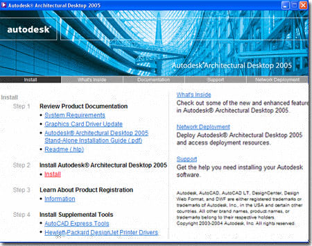
Desktop 2005 now comes with 3 Installation CD's labeled 1, 2 and 3. When you insert disk 1, you should get a menu with all sorts of installation
options as illustrated to the right. You can return to this menu at any time in the
future to add items to your current installation, make repairs or simply to read the
numerous .pdf documents offering information on anything from Network Installation
Solutions to basic command use. Architectural
Desktop 2005 now comes with 3 Installation CD's labeled 1, 2 and 3. When you insert disk 1, you should get a menu with all sorts of installation
options as illustrated to the right. You can return to this menu at any time in the
future to add items to your current installation, make repairs or simply to read the
numerous .pdf documents offering information on anything from Network Installation
Solutions to basic command use.
|
 |
Architectural
Desktop 2005 Installation Types
| DiskCost |
Architectural Desktop 2005
Full Install ~= 1.014GB |
Typically I recommend that users install
based on the Full or Custom options but now ADT only offers "Standard" or
"Custom". The only problem with choosing "Custom" is that
inexperienced users may inadvertently omit important components but then you
could always turn "Custom" into "Full" by selecting all components.
Metric users will most likely want to use the Custom option so they can
install both the Metric and D A CH Content at the same time rather than
return to Add it later.
Some of the key items that can be installed or left out are
Metric Content, Tutorials/Samples and Viz Render.
Even if you are not a Metric user, I do recommend installing this content because there
are many Metric Multi-View Blocks that are quite useful to Imperial Units users ( outdoor
furniture, for example ). Viz Render (now in version 2) is a "dumbed-down"
or light
version of Autodesk Viz and has been included to help ADT users take advantage of ADT's
new Material Styles. Autodesk Viz was slated to be discontinued but
apparently the user-base uproar forced a snappy return to market with only a
six-month nap. For many, including me, Viz ( the full package ) is far
more pleasant to work with because you can actually create in it as opposed
to Viz Render where you can only make Materials and Render. and it is
unclear what, if anything, will replace it. Because of the Material
correlation between Viz Render and ADT, you should definitely install this
option.
|
 |
|
Custom Installation Options for ADT 2005
If you choose to take the "Custom" route
on the Installation dialog, discussed above, then the options you will have
to select from are as listed in the image to the right.
Note:
If you are not familiar with Autodesk Viz or Viz Render, then what you need to know is
that this is a separate Autodesk Product that runs independently of Architectural Desktop
but has the capability to Link with ADT files much like Xref's. Its primary function
is to Render your work for optimum presentation output in animated, print or web formats.
You can activate the Viz Render application from within Architectural Desktop by
typing "VizRender" on the command line. |
 |
The Options dialog box
| Menu |
Format >
Options... |
| |
|
| Keyboard |
OP |
| Links |
|
Architectural Desktop, like AutoCAD, has unique settings in
the Options dialog box; formerly known as Preferences. Use the
Arrow buttons, upper right, to tab to the right where you will find all of the AEC Options
tabs that affect how ADT functions.
All of the text boxes with drawing icons represent current
drawing settings and will not be set for all of Architectural Desktop; i.e, they are local
and not global settings. If you save these settings in a template file though, you
can use them in a more global fashion.
You should find five tabs that are specific to ADT: AEC
Editor, AEC Object Settings, AEC Dimensions, AEC
Content and AEC Project Defaults. Some of the settings on
these tabs will be discussed in this guide where they relate to the objects they
affect. For the full break-down of all these settings and all of those on the other
tabs, refer to the Architectural Desktop Deployment eGuide.
|
Note:
For users of previous releases of ADT, you may be surprised to find that familiar settings
no longer exist on the AEC tabs. Important settings such as how Openings are
measured are now part of the Object Properties and these can be set on an object-by-object
basis or as part of the Tool Palettes Icon Properties ( right-click over
a Tool Palettes icon to access its Properties ). |
| 4Getting Started |
4-i INTRODUCTION |
Architectural
Desktop Projects
| Menu |
Window > Project
Navigator Palette |
 |
|
| Keyboard |
AecProjectNavigator
or [Ctrl+5] |
| |
AecProjectBrowser |
| Links |
|
 For those who have followed along with AutoCAD and ADT since the
2000 series, you will understand the humor of the Today Window. In
ADT 4 and 5, the Today Window was removed leaving the old "traditional startup
dialog box" as the default Startup Dialog ( see below, right ). For
those few who might actually have used the Today Window, fear not, it has evolved and
migrated over to the Project Browser Window - illustrated to the right. For those who have followed along with AutoCAD and ADT since the
2000 series, you will understand the humor of the Today Window. In
ADT 4 and 5, the Today Window was removed leaving the old "traditional startup
dialog box" as the default Startup Dialog ( see below, right ). For
those few who might actually have used the Today Window, fear not, it has evolved and
migrated over to the Project Browser Window - illustrated to the right.
With the Project Browser and its companion, Project
Navigator, ADT 5 offers one of its best new features. In essence, these
tools provide a type of project management system within the core program that not only
helps structure folders but the objects within files and how those objects need to be
assembled for final plotting sheets. The primary tool for managing all of this
drawing data is the Xref and by using the Project Navigator you will soon find the use and
management of Xref's so fluid that it may be the biggest change you have faced in your
AutoCAD/ADT work in many years.
This whole project system is far more sophisticated than
what I can describe in a few words and documenting it will become a separate topic for the
Architectural Desktop Deployment eGuide. |
 Illustrated to the left is the AEC
Project Defaults tab where you can set the Project Search Path for the Project
Browser so users can use this tool to add new projects under existing or new mapped drives
( or even local folders ) in your office.
Default Project Location Search Path
C:\Documents and Settings\[User Login Name]\My Documents\My Autodesk Architectural Desktop
Projects |
| Choosing an ADT Template In ADT
5 you can now start drawings based on the Acad.dwt
or even from scratch because the template files used for those options
have now been updated for ADT. If you use the Browse... button on
the Create New Drawing dialog and select a template file that was not
configured for ADT or Open an existing drawing that was not created with ADT, you will
find that a lot of settings are missing. This means that template files are
basically paramount to a successful implementation of ADT but don't let that limit you to
the template files that come with ADT; i.e., build your own once you know what makes them
special. In the Architectural Desktop Deployment eGuide you will find all of the
information required to import template file settings into legacy files should that become
an issue in your office.
Illustrated to the right I show the default Imperial
and Metric Template Files that come with ADT 5. This list is a vast
improvement on the template files of the past and I can now recommend the use of any of
the four "Architectural building model and view (...).dwt"
files. There are two for Metric and two for Imperial and the only thing you really
need to consider in selecting one of them to start with is whether or not you want to use
the Color Table (.ctb) or Style Table (.stb) system
for pen management; these are also referred to as Color Dependant Plot Styles
and Named Plot Styles, respectively. My recommendation is to use
what you are currently familiar with and in most offices that is the Color Table ( .ctb )
system because it is the same system AutoCAD users have been using since the first
release. You should know, however, that Autodesk is recommending the use of Style
Tables and may make this method less of an option in the future ( so the rumor mill
informs me ). The reason for the push on using Style Tables is so the use of the new
True Color System, including Pantone colors, can be implemented without the limitations of
255 Colors.
Illustrated to the right I show the default Display
Configurations from the Architectural building model and view (...).dwt"
template files and how you can now change these by picking on the arrow button in the
lower right of the ADT Application on a new bar called the "Drawing Window Status
Bar". This bar offers another arrow on the opposite side that activates another
pop-up menu with Plot, Setup, Link and eTransmit options ( among others ). The
middle portion of this bar will not display anything until you begin to work with the
Project Management tools including the Project Browser and Navigator discussed above.
|
 For Layout tabs, you should notice that
these template files only offer one that has been named "Work".
You may rename this, change the Layout Settings and do whatever else you might normally do
for a Layout or you can just Delete it and create a New one. Just make sure that
once you have created one or more Viewports, that you use the Display Configurations menu
to set a Display active. Keep in mind that you are not restricted to or
limited by most of the default settings found in these template files; they are just
default examples to help those unfamiliar with the deeper inner workings of ADT, be
productive sooner. |
| Starting a Drawing One of the first things you will have to do in Architectural
Desktop, after choosing a template file, is figure out the GUI and how to manage all of
the stuff you have to work with. Illustrated to the right I show just a few of the
graphic tools that you will need to interact with on a regular basis and an
example of how I keep my numerous Palettes arranged. I found that
docking the Palettes and turning them On and Off as needed worked be for me
but now it's time for you to figure out how you like to arrange them.
The Palettes and DesignCenter will remember their last
position so you may want to find good locations for these tools and size them for a
comfortable read. On dual monitors, you can move the Palettes and DesignCenter over
to the second monitor. As discussed above, I don't advise using the Transparency
option for the Palettes as it tends to put a strain on the Graphic Card's resources (
unnecessarily). I also don't recommend keeping the Properties Palette up and Docked
at all times since it will need to refresh constantly as you select objects on the screen.
Also illustrated to the right is ARCHIdigm's own custom
menu system for using and learning ADT. This menu system is free to all subscribers,
is easy to install and remains completely independent of your ADT installation so you
don't have to worry about messing up your configuration. This menu uses most of the
icons from Architectural Desktop 3.3 but incorporates many of the new icons in AutoCAD
2005 and Architectural Desktop 2005 - for more see PowerSTRIP.
After you have selected a Template File to start your new
drawing, you will need to go through a few steps for configuring this drawing for proper
use. To learn about what to do next, go to Part
1 - AEC SETUP - DISPLAY and read up on the Setup information but don't worry
too much about the Display information; instead, skip to Walls, Openings and so on. |
For those migrating up, you can continue your
work in ADT 5 but you cannot go back. ADT 3 - 3.3 files appear to come in okay in
our tests so far and bring with them all that you would expect ( Display Configurations
and so on ). We are however, adopting a policy of finishing old work on old software
and staring new work on new software. As usual, we are also finding that others are
not upgrading as fast as some of us are capable of so working in ADT 3 - 3.3 may last
longer than preferred. |