| 1Schedule - Access |
1-18 SCHEDULES |
Schedule Toolbar
How do I get this toolbar?
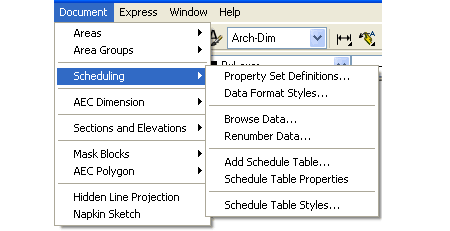
You can also acquire access to some of these commands from the Alternate Document
pull-down menu. From the Document pull-down menu, pick Scheduling
> and cascade to the various Schedule related commands. This toolbar is
an optional tool and is not needed to use this guide but may help.For the tagging
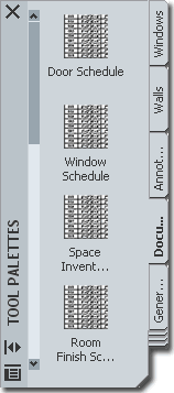
symbols, see the Tools Palette illustrated below. |
 |
 |
| Schedule pull-down menu and Tool Palette
 Scheduling
is a topic that could be a book in itself and it is definitely a subject
that I continue to learn about. Therefore, I consider this chapter or
"part" a work in progress that I hope to add to over the next year or so. Scheduling
is a topic that could be a book in itself and it is definitely a subject
that I continue to learn about. Therefore, I consider this chapter or
"part" a work in progress that I hope to add to over the next year or so.
You can basically break the scheduling system down into
three primary categories: Tags, Data and Tables.
Tables require Data and Data is often, but not always, controlled by Tags.
When you tag an Object, data is usually Attached at the same time. You don't always need Tags to create Tables but you definitely need Data.
An example of this can be demonstrated by using the
AddAllPropSets command to fill out
a Door or Window Schedule without tagging any of these Objects. |
 Note:
The default Tool Palette has a rather scant list of Scheduling tools available for this
type of work. You can easily populate the Documentation tab of your Tool Palette
with many more Scheduling tools by using the Content Browser. |
|
2Loading Schedule Table Styles |
2-18 SCHEDULES |
Opening Schedule Table Styles in the Style Manager
| Menu |
Documentation>
Schedule Tables> Schedule Table Styles... |
 |
 |
| Keyboard |
TableStyle |
| Links |
Schedule Table Styles - for how to
create and edit a Schedule Table Style |
 In
order to Add a Schedule Table to your drawing or project, you must load a
Schedule Table Style. Unlike numerous other Object Styles, there is no
default "Standard" Schedule Table Style. In
order to Add a Schedule Table to your drawing or project, you must load a
Schedule Table Style. Unlike numerous other Object Styles, there is no
default "Standard" Schedule Table Style.
You can access the full list of Schedule
Table Styles in the same Styles folder where all other Object Styles are
stored. See illustrations right and left.
Illustrated to the left I show a full list of
the Schedule Table Styles that come with ADT in the
Schedule
Tables (Imperial).dwg file. Table Styles that have the term
"Project Based" in their Names were designed to
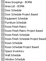 work with
the Project Browser and Navigation System. What that means is
basically just another way to collect more automatic data such as Door Tag
numbers tied to Floor Levels using Project Based Tags. The whole
Project File System is new to ADT 2004 and in its infancy so don't feel
compelled to use it unless you find it beneficial for managing floor levels. work with
the Project Browser and Navigation System. What that means is
basically just another way to collect more automatic data such as Door Tag
numbers tied to Floor Levels using Project Based Tags. The whole
Project File System is new to ADT 2004 and in its infancy so don't feel
compelled to use it unless you find it beneficial for managing floor levels. |
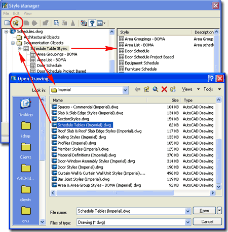
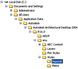
For
local installations of ADT, you are likely to find the Imperial or Metric
Schedule Table Styles in the Styles Folder as illustrated to the
left. The full path to this location may vary but typically it is as
illustrated. On a Network based installation of ADT, these Styles should be on a
captured drive (like "G:\offices standards") or similar location with a folder
name that indicates Styles. Consult your CAD or IT manager if you cannot locate the
Styles Folder.
Schedule
Tables (Imperial).dwg
Schedule
Tables (Metric).dwg |
Setting the Drawing Scale for Annotation Symbols
and Schedule Tables
| Menu |
Format> Drawing
Setup... |
 |
 |
| Keyboard |
AecDwgSetup |
| Links |
Drawing Setup Dialog Boxes
- for how to access this dialog and for more informaiton on the various settings. |
Before you start using Tags and Schedules, setting the
Drawing Scale to the desired printing output is extremely important because you can't
change your mind at a later date and hope to have all of the Tags and Schedules update
automatically; in fact, they don't update at all. Some Tags have been
designed to change size based on the current Display Configuration. Since Schedules are basically
unbound by scales they may not be a problem but having tens, if not hundreds, of Door and
Window Tags to fix is a nasty task best avoided.
Set your preferred Drawing Scale or go to
Other... at the bottom of the Scale tab on the Drawing Setup dialog
box and create your own ratio. If you are new to the scale concept in
AutoCAD, this is really just a way of telling the program what scale you plan to print at.
This number is then used to multiply against symbols, text and dimensions so they
print correctly for your specific scale. In other words, a scale of 1/4" =
1''-0" equates to a ratio of 1:48. The number 48 is now multiplied against a
dimension arrow, for example, that is set to be 1/8" long when printed; but, on the
screen it will measure out as ( 48 x 1/8" ) 6".
It has almost become a defacto standard in CAD to use
1/8" for Annotation Plot Size but if you think in terms of Points,
10pts = 1/12 inch. This equates to 15.875mm for the Metric people but I would
use 15mm myself since I've always liked text a bit smaller than 1/8". In both
cases, office standards really determine what you need to use so make sure to check
existing plans.
|
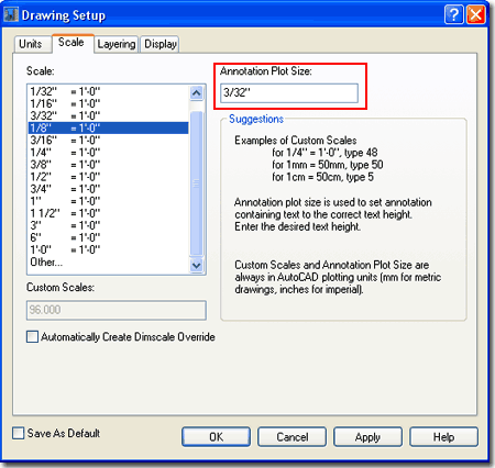
Originally the Annotation Plot Size was set to
1/8" for the Imperial users but most designers found that this produced
Symbols with Text that were too large. In ADT 2004 the number was
changed to 3/32" as a new default and it seems to work rather well for most.
I, of course, recommend that you run some tests before accepting this value.
Typically it does not need to be changed when you change the Drawing Scale. |
| Display Edit Schedule Data Dialog During Tag Insertion
Illustrated to the right is the Options (
type "OP" ) dialog box with the AEC Content tab active.
Content Path - this is where you can set
your ADT to see a common folder on an office's network server. By keeping all of the
Content in one place, it's growth and change can be managed much better ( just like a
block library ). Once changed, the icons will automatically look for this Path.
|
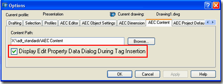
Display Edit Schedule Data Dialog During Tag
Insertion - this is one of those options that you wind up living with though you
can turn it off so easily. Unchecking this option is much like making Attributes
Preset upon insertion. To see what this thing does, try attaching a Window or Door
tag to a Window or Door and look for the Edit Schedule Data
dialog box.
Uncheck this and repeat the exercise. Then, decide which option is better.
Unchecked, right? I leave it unchecked. |
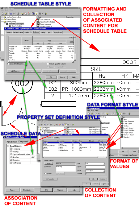
| Schedule Anatomy Illustrated to
the right are all of the various dialog boxes and architectural objects required to make
one single Door Schedule Table item.
Though you can successfully produce a Schedule Table with
ADT's default configurations, once you want something different you will need to know
where to go to make that change. And though it may look terribly complicated, once
you see all of the various pieces, it becomes rather simple.
Tagging Objects:
The first thing we need to look at is the object you want to put in your Schedule.
If you notice my example Schedule, right, there is one Door Marked "?"
and that is because it was not Assigned Schedule Data. A Door Schedule, will read
Doors without Door Tags but the best way to get a proper Schedule Table it to begin
Tagging your objects ( of course not all objects will have tags and thus you don't tag
them but you still Assign or Attach Schedule Data).
Attaching Schedule Data:
When you Anchor a Tag to an Object,
Schedule Data is usually Associated with the Object by
default. In some cases, particularly custom cases, you will have to use the Edit
Schedule Data dialogue box to Associate other Schedule Data which comes from the Property
Set Definition Styles.
Property Set Definition Styles:
The information or Content that goes into Schedule Data come from the
Property Set Definition Styles where the individual bits of information about a particular
object is Named, Described, Formatted and otherwise organized. Since the Data or
Content of what we want about architectural objects varies so much, from numbers, to
currency, to sentences and so on, the Formatting of this Content is controlled by yet
another Style called the Data Format Style.
Data Format Styles: ( the very bottom of
Schedules )
The way measurements are written in the Schedule Table as 3'-0" or 1000mm is
entirely controlled by the Data Format Style. These Styles are much like the
Dimension Styles in AutoCAD where you make decisions about Leading and Trailing zeros,
Prefixes and Suffixes and so on.
Schedule Table Styles: ( the very top of
Schedules )
At the very top of all this controlling, collecting and formatting stuff is the Schedule
Table Style which allows you to gather Schedule Data and line it up in columns
and rows according to your needs. In many cases, the Schedule Data comes in blank
from the Property Set Definitions and simply act as Attributes for you to fill out as you
create your project. These Data items are things like Make, Manufacturer, Cost,
Color and so forth. Once these items have been filled out, they can appear in your
Physical Schedule automatically or upon a Schedule Update. The Schedule can also act
as a filter where not all information associated with an object is reported on one
Schedule but perhaps two or more. |
 |
|
3Adding Tags |
3-18 SCHEDULES |
Adding Door & Window Tags
| Menu |
N.A. |
 |
 |
| Keyboard |
AecDcSetImpDoorWindowTags
- imperial |
| |
AecDcSetMetDoorWindowTags
- metric |
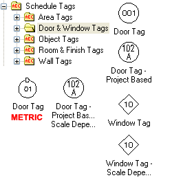 Adding
Door and Window tags is fairly easy when you have just a few to
deal with but when you have 50 or more it becomes rather tedious.
There is no automatic way to tag a whole series of openings in some logical
order; you actually have to Select each Object and tag them one at a time in
the order you want the numbers to ascend. Should the order change, ADT
offers a Renumbering tool. Adding
Door and Window tags is fairly easy when you have just a few to
deal with but when you have 50 or more it becomes rather tedious.
There is no automatic way to tag a whole series of openings in some logical
order; you actually have to Select each Object and tag them one at a time in
the order you want the numbers to ascend. Should the order change, ADT
offers a Renumbering tool.
The default Tool Palette offers a few
of the Door and Window Tags but you can use the DesignCenter to
access the whole set illustrated to the left. The process of Tagging
any Object involves dragging the Tag Symbol to the screen and then Selecting
the Object to be Tagged. The Final step involves responding to the
command line options for locating the Symbol; hitting Enter will
automatically Center the Symbol.
Once you have completed the step for locating
your Symbol, you may find that the
"Edit Property Set Data" dialog
pops up on your screen. This dialog provides the option to fill in
information for your Schedule Table or other Exporting of Data but you can
deactivate this feature if it becomes irritating.
Tagging Doors and Windows should prove to be
straight forward and the Data you acquire from this work should also proved
to be rather useful in your Schedule Tables. When it comes to other
Objects such as the Door/Window Assemblies, Curtain Walls and custom
solutions for things like Skylights, significant problems begin to appear.
Illustrated to the right I show how both the default Door and Window Tags
can be used on Door/Window Assemblies begging the question of how to
Schedule this Object Type. In either case, you should find that the
results are basically the same: you get a single report in your Schedule
Table based upon the exterior Frame Dimensions with no identification of the
Objects, such as Doors, within the Assembly. If you happen to have
Doors and Windows within your Door/Window Assembly, you can actually Tag
those Objects independently. Since ADT does not come with any unique
solutions for solving this problem, you may want to consider creating an
Assembly Schedule and not permit the Tagging of these Objects with the Door
and Window Tags - see Property
Set Definition Styles. Even if you do this, a user will always
be able to accidentally use a Door or Window Tag on any Doors or Windows
within a Door/Window Assembly so this can prove to be a frustrating problem
if you work with these Objects and Schedule them.
For skylights, using a Window Object
has proven to be the easiest solution for me because you can Tag it as a
Window and have it labeled as a skylight in your Schedule Table. Some
"gurus" tout using Roofs and Roof Slabs but they prove to be much more
difficult to Schedule. Curtain Walls can be use to create great
skylights and can be included in a Window Schedule but the information may
not prove to be very useful as in the case of curved or arched skylights.
For situations like this, I simply turn to manual additions to my schedules.
Again, using a standard Window in the place of a fancy skylight design can
be used as a place-holder in your schedule - you can even put the window on
the Defpoints layer so it won't print.
To add or edit information on Door and Window tags, see
->
Edit Schedule Data dialog box |
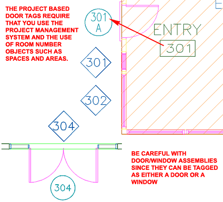
Illustrated above I show one of the Project
Based Door Tags that should jump out at most users who have multiple
floors to deal with. The only problem with these Tags is that you have
to know a bit more about ADT and use that knowledge in order to take full
advantage of these Tag types. In order for the Tag to automatically
read the Room Number + the Floor Number ( 3 = Floor Number and 01 = Space
Number ), you need to use the Project Management System and some form of
Room Number identifying Object like a Space, Area or Slab. The Space
Object, illustrated above as diagonal lines, reads the Floor Number from the
Project Data while the Project Based Door Tag reads the Space Property Set
Data when Tagging the Door. Frankly, though this is an impressive
feature, I am not a fan of this Tagging System since it requires some manual
input of Data. What I do like is the addition of the Floor Level as a
Prefix and I may attempt to create a custom Door Tag that takes advantage of
that feature without other Text in the Symbol.
|
Adding
Object Tags
| Menu |
N.A. |
 |
 |
| Keyboard |
AecDcSetImpObjectTags
- imperial |
| |
AecDcSetMetObjectTags
- metric |
| Links |
Structural Member Tags - for information on tags that don't work. |
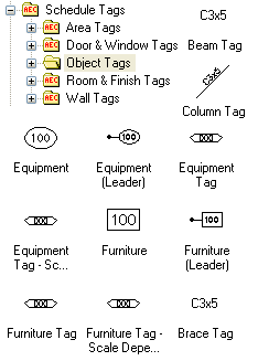 Adding Object tags is fairly easy but
often disappointing because the values or information you get in the tag, automatically,
usually are simple defaults unlike the automatic numbers for the Doors and Windows. Adding Object tags is fairly easy but
often disappointing because the values or information you get in the tag, automatically,
usually are simple defaults unlike the automatic numbers for the Doors and Windows.
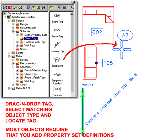
Illustrated to the right, I show a few common simple object
types and their matching tag objects. If you want Numbers in your object tags, you
have to make sure that your objects have a Property Set Definition Style Added to them.
You can read about Adding Property
Set Definitions below.
To add or edit information on Object tags, see ->
Edit Schedule Data dialog box |
 |
Adding Room & Finish Tags
| Menu |
N.A. |
 |
 |
| Keyboard |
AecDcSetImpRoomAndFinishTags
- imperial |
| |
AecDcSetMetRoomAndFinishTags
- metric |
| Links |
Part 11 - Spaces - for information
on Space Objects. See also
Generate Spaces for how to create
Spaces based on surrounding Walls. |
| |
Part 20 - Areas - for information
on Area Objects |
| |
Slabs and Room Tags - for a trick to
make these Tags work on Slabs. |
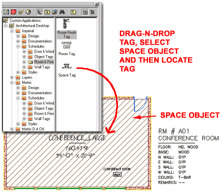
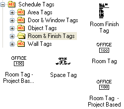 By
reading the titles for the various Room and Finish Tags, you can probably
guess at the Object Styles these Tags were designed for. By default
then, Room, Space and Room Finish Tags only work on
Area and Space Objects. By
reading the titles for the various Room and Finish Tags, you can probably
guess at the Object Styles these Tags were designed for. By default
then, Room, Space and Room Finish Tags only work on
Area and Space Objects.
To add or edit information on Room and Finish tags, see
->
Edit Schedule Data dialog box |
 |
Adding
Wall Tags
| Menu |
N.A. |
 |
 |
| Keyboard |
AecDcSetImpWallTags
- imperial |
| |
AecDcSetMetWallTags
- metric |
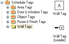 Adding Wall tags is a matter of choosing
one of the two Wall tag types and dragging it into your drawing. Adding Wall tags is a matter of choosing
one of the two Wall tag types and dragging it into your drawing.
From the DesignCenter, you simply drag-n-drop
one of these symbols into your drawing and then select a Wall
for it to be associated with. You must select a Wall because that is how the tag
derives the information used to generate a schedule table.
When you have selected a Wall object, the tag will need to
be positioned and you can either manually pick a position or hit enter to
automatically Center the tag on your Wall. The simple Wall tag only
has to be positioned while the Leader Wall tag needs to be placed by first picking the
beginning point of your leader, the second point of your leader and the final position of
your Wall tag.
|
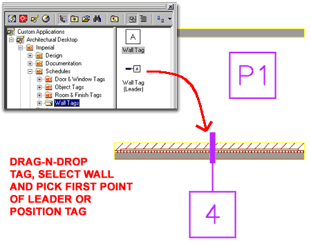 Illustrated
above are examples of both Wall tag
types.
Imperial and Metric Wall tags are identical.
To add or edit information on Wall tags, see ->
Edit Schedule Data dialog box |
Adding Area Tags
| Keyboard |
AecAnnoScheduleTagAdd - but
it is better to use the drag-n-drop technique since it scripts several settings. |
| Links |
Part 20 - Areas - for more information on Area Objects |
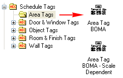 Both
the Imperial and the Metric Content Folders now contain Area tags
and they are basically identical. For both Imperial and Metric use, the Area tag is
based upon a BOMA standard indicating the Room Number, Room Name, Net Usable Area (NUA)
and Net Rentable Area (NRA). There are two versions of the same tag where the
"Scale Dependent" one will automatically change size for Low, Medium and High
Detail Display Configurations ( rather handy for those presentation plans on A-size paper
). Both
the Imperial and the Metric Content Folders now contain Area tags
and they are basically identical. For both Imperial and Metric use, the Area tag is
based upon a BOMA standard indicating the Room Number, Room Name, Net Usable Area (NUA)
and Net Rentable Area (NRA). There are two versions of the same tag where the
"Scale Dependent" one will automatically change size for Low, Medium and High
Detail Display Configurations ( rather handy for those presentation plans on A-size paper
).
You can also use Room tags on Area Objects if you are
looking for less information with the tag or a different structure to the area report.
|
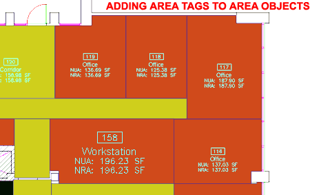 In ADT 3.3, under the Metric D A CH folder there were many
more tag options for Areas and even Area Groups that appear to have been discontinued.
If you happen to have that release around you may want to migrate some of these
tags if you need more options. You can also create your own from scratch or by
modifying one of the BOMA Area Tags
You can learn more about these tags under the Customizing and Tips section of Part 20 - Areas. |
|
4Modifying Tags |
4-18 SCHEDULES |
Modify Tags
(Multi-View Blocks)
| Mouse |
Select Tab
Object and double left-pick or right-click to invoke object specific
pop-up menu. |
| Links |
Part 25 - AEC
Blocks - Profiles - for more information on Modifying Multi-View
Blocks |
 Schedule
Tags are usually Multi-View Blocks that have been configured with
the AEC Content
Wizard to react with specific Object Types and introduce Property
Data. This means that when you attempt to Modify the Tag Object, you
will find that the options are limited to those of MvBlocks as illustrated
to the right for a common Door Tag. In the discussion below I will
provide an overview of what you can change by working directly with the Tag
Object; keep in mind that the real subject of Part - 18, is the
Data that the Tag helps to present and organize. Schedule
Tags are usually Multi-View Blocks that have been configured with
the AEC Content
Wizard to react with specific Object Types and introduce Property
Data. This means that when you attempt to Modify the Tag Object, you
will find that the options are limited to those of MvBlocks as illustrated
to the right for a common Door Tag. In the discussion below I will
provide an overview of what you can change by working directly with the Tag
Object; keep in mind that the real subject of Part - 18, is the
Data that the Tag helps to present and organize.
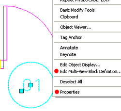
Illustrated to the left I show the
object-specific pop-up menu as it appears when working with a common
Door Tag. As you can see, this menu offers the same options as those
found when working with regular MvBlocks and an extra set of options for Tag
Anchor (see discussion below).
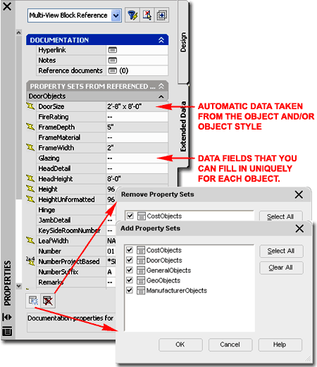
The Properties Palette, illustrated to
the right offers the same options you typically find for all MvBlocks but
since Tags use Attributes to display the Numbers or Letters as part of the
Symbol, you should also find the option to Modify those Attributes directly.
Under the Scale section of the
Properties Palette, you will find the Scale value fields that are
automatically set when you drag-n-drop a MvBlock into your drawing. For
many objects that are Print Scale dependant, such as Tags and Electrical Symbols, the Scale
value is determined by the Drawing
Scale as set on the Drawing Setup dialog box. If you need an object to be a different dimension in Width,
Depth or Height, you can change these values to match what you want. In some cases,
however, this will create odd results; such as if you attempt to make a Wall tag wider (
the text will become elongated ).X - width of object,
Y - depth of object, Z - height of object. |
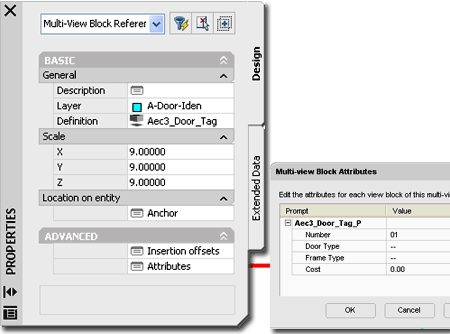
The Anchor dialog box provides the option
to position your MvBlock using X, Y and Z coordinate value fields - See
Multi-View
Block Reference Properties - Location dialog.
The Insertion Offsets dialog
provides the option to control the insertion position of individual Blocks
within an MvBlock but since most Tags only use one Block for Plan Display,
you may not find other Blocks listed here. |
|
Tag (Multi-View
Block) Properties - Attributes dialog
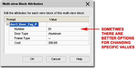
On the Multi-view Block Attributes
dialog box for a Tag Object, you should find a list of all the editable
Attributes for that Tag. Do not confuse the Attributes with the Data
though some Attribute information is often included in Schedules.
Attribute information is usually for the text that you want to display
within the Symbol as is the case with most AutoCAD Block Attributes.
Some of the default Object Tags, such as the Door Tag discussed above and to
the right, offer additional Attribute fields that can be included in the
Schedule or other forms of extracted data. These extra fields provide
the option to include information that is unique to each Object though it
may be part of the same Object Style; i.e., two identical Doors but labeled
with different Tag Numbers.
In some cases, such as the Tag Numbers
on Doors and Windows, using the "AecPropertyRenumberData"
command may prove to be a much better option for Modifying the numbers. |
 |
Tag (Multi-View
Block) Properties - Extended Data tab
| Keyboard |
PropertyDataEdit - for direct access to the Extended Data tab |
When it comes to Modifying Object Tags, the
serious topic begins on the Extended Data tab of the Properties
Palettes. Though most Objects have Property Data Sets assigned at
the Style Level, sometimes you may create one where you forgot to Add any
Property Sets. In cases like this you may notice that information is
missing in your Schedules ( often expressed by a "?" ). You will also
find that the Data you are looking for will not be listed on the Extended
Data tab of the Object Properties Palette. Property Data Sets can
always be Added or Removed from Objects, as illustrated to the right, as
long as Property Data Definition Styles exist in the current drawing and
that they can be applied to the Selected Object; i.e., not all Property Data
Definition Styles can be applied to all Objects.
One rather interesting and helpful feature in
ADT regarding Property Data Sets is that the act of Tagging an Object
usually results in the Attachment of one or more Data Sets as well so if you
find that you have Doors, for example, that don't have their Property Data
Sets Added on the Extended Data tab, you may want to Tag them before
attempting to Add the Sets Manually.
Tags will Attach Property Data Sets to
Objects but you may want more Data than what the Tag brings to the Object
and in cases like that you may have to Add it manually. How you manage
your Schedules, the Data you want in them and any other Data you may want to
extract to Spread Sheets, will determine when and where you will Add the
Property Data Sets. Obviously the most effective place to Attach this
Data is at the Style Level but that also assumes you have the foresight to
prepare your Property Set Definition Styles proper to starting your project.
Fields with a lightening bolt before them
cannot be edited because the Data is extracted directly from the Object or
Object Style.
Fields that have lightening bolts with other
symbols such as
 , ,
 or or
 indicate that not only does this data
come from an automatic source but that special conditions are part of the
data such as formulas, locations and Project Specifications>
Fields that have the symbol "--" in them are
open and can be filled in with text and or numbers. |
 |
|
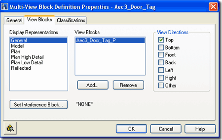
Multi-View Block Definition Properties dialog box
Another
Modification option that is available from the object specific pop-up menu is
"Edit Multi-view Block Definition..." You can read up
on this subject under Multi-view Blocks but I included the topic here
because you may find that some Tags don't appear when you want them to and
this may be a quick fix that you will need to know about.
If you have one or more Tags that don't
display for the Reflected Display Representation or vice-versa, for example,
you can use the Add... button to Add the Block Name for the
Display Representation you want and set the View Directions to
Top. This Modification will affect all of the same Tags in the
current drawing.
|
 |
| Tag
(Multi-View
Block) - Anchors
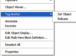 The
Object specific pop-up menu for Tags will offer the option to
Release the Tag or Set another Object as illustrated to
the left. Generally, I have not found either of these option very
helpful because if you desire to remove a Tag, you can just Delete it and if
you wish to transfer a Tag to another Object, it is better to use the
Tagging process whereby Property Data is automatically attached to the
Object. If you attempt, for example, to Set one Door tag to another
Door that has no Data, that Tag will Anchor but it will not transfer any
Data. The
Object specific pop-up menu for Tags will offer the option to
Release the Tag or Set another Object as illustrated to
the left. Generally, I have not found either of these option very
helpful because if you desire to remove a Tag, you can just Delete it and if
you wish to transfer a Tag to another Object, it is better to use the
Tagging process whereby Property Data is automatically attached to the
Object. If you attempt, for example, to Set one Door tag to another
Door that has no Data, that Tag will Anchor but it will not transfer any
Data.
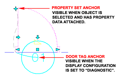
Illustrated to the right I show to
interesting Anchor related Graphics that currently don't do much but may in
the future. In the template files that come with ADT, you should find
that there is a Display Configuration called "Diagnostic" and
when this is set active, you should see arcs between Tags and their target
Objects. This allows you to see which Tags are Anchored to which
Objects but Tags still do not Move with Objects as they should. Once
an Object has Property Data Attached to it, as the Door in the illustration
to the right, you should find that there is a Property Data Location Anchor
when the Door Object is Selected. At the time of this writing I have
no explanation for what you can do with this Anchor but I suspect we will
all know what we can do with it in a future release of ADT. |
 |
|
5Schedule Data |
5-18 SCHEDULES |
Edit Schedule Data dialog box
| Menu |
N.A. |
 |
 |
| Keyboard |
PropertyDataEdit |
| Mouse |
Double
pick on Tag or Tagged Object to invoke the Properties Palette and then
Select the Extended Data Tab |
 Objects
do not have to be Tagged in order to have Property Data Sets attached to
them so when you wish to Modify Data Fields, you can either Select the
Object or the Tag ( if one exists ). As discussed earlier, not all
Data can be modified since it may be derived automatically from the Object
and/or Object Style but there are numerous Data Fields that require manual
input at some point in a project. Objects
do not have to be Tagged in order to have Property Data Sets attached to
them so when you wish to Modify Data Fields, you can either Select the
Object or the Tag ( if one exists ). As discussed earlier, not all
Data can be modified since it may be derived automatically from the Object
and/or Object Style but there are numerous Data Fields that require manual
input at some point in a project.
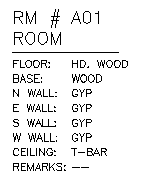
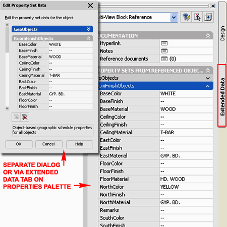
Illustrated to the left and right I show one
of the default Room Finish Tags and some of the Data Fields it
offers when Attached to a common Space Object. One of
the first things you may notice is that the Tag itself does not display all
of the Data Fields seen under the RoomFinishObjects section of the Extended
Data dialog. A Tag does not necessary have to display any of the Data
Fields and if you want to Add or Remove Data displayed by the Tag, you will
need to read up on creating your own Tags.
The full list in your Schedule Data comes from the Property
Set Definition Styles and you add or remove these Styles with the Add..
and Remove... buttons on the bottom of the Edit Property
Set Data dialog box. This is how you could start with basic Window sizes and numbers, for example,
and then later add another Property Set Definition for more detailed information like
cost, manufacturer and so on. |
 |
| Edit Schedule Data - Add Property Set
When you wish to Add Property Sets to an
Object you can use the Add Property Set button on the Extended Data tab of
the Properties Palette or on the Edit Property Set Data dialog, illustrated
to right. What you need to understand is that for many Objects, the
process of Tagging them also Adds or Attaches the Property Sets so you may
not need to do it manually. In addition to that, some Property Sets
are Style Based and not Object Based and it is fairly easy to misunderstand
the difference or even add redundant Property Sets. When you work at
the Object Level, as discussed here, you will only see Object Based Property
Sets.
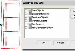 Illustrated
to the left I show an example of how you might want to work with some
Multi-View Blocks that you want to tally or include in a Schedule. If
this example Sofa was tagged, I would probably not need to Add and Property
Sets manually, but if I don't want to Tag it or I want to Add other Property
Sets, this option is fantastic. And, since MvBlocks are not Style
Based, you can't Add the Property Sets at any other level anyway. Illustrated
to the left I show an example of how you might want to work with some
Multi-View Blocks that you want to tally or include in a Schedule. If
this example Sofa was tagged, I would probably not need to Add and Property
Sets manually, but if I don't want to Tag it or I want to Add other Property
Sets, this option is fantastic. And, since MvBlocks are not Style
Based, you can't Add the Property Sets at any other level anyway.
|
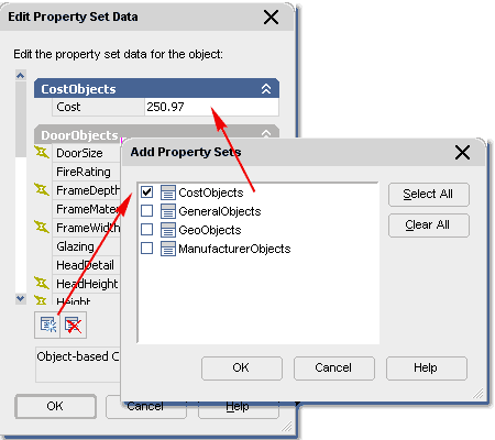 Now, for the Door example illustrated to the
right, the process of tagging it should add most of the Property Sets you
will want but there are times when you may want other information and you
will need to decide on how that information should be Added. By using
Cost as an example, we should be able to agree that the Cost of Door Objects
will vary per Object; even within one Style Family. You may find that
the Door Styles that come with ADT have Cost as part of the Style Based
Property Set ( already Added ), but this assumes that all Doors of one Style
Family have the same Cost. By Adding the "CostObjects" Property
Set manually to a Door Object, you can now fill in the Cost of that single
individual Door.
Ideally, if you decide that something like
Cost should be Added at the Object Level, it would be added automatically as
part of the tagging process but if you want that type of behavior, you'll
have to make some customized changes to ADT's default tags, property sets
and possibly even schedules.
|
Browse Property Data dialog box
| Alt.Menu |
Document> Scheduling> Browse Data... |
| |
|
| Keyboard |
PropertyDataBrowse |
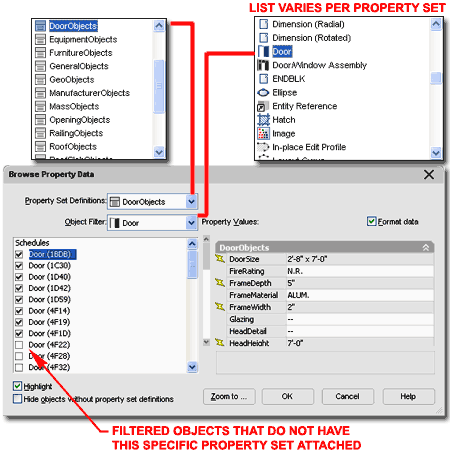
If managing data in your projects becomes a
major task, one of the most impressive tools for filtering through Objects
and their Property Data Sets is the Browse Property Data dialog box
illustrated to the right. With this tool you can set a specific
Property Data Set and either look for All Objects that this Set can be
Applied ( Attached ) to or Filter the list of Objects to one Type.
Once you have located Objects that require Modification, you have several
options that will assist in making those changes easier.
Schedules
Under this section you may also see file names for Xref'd files which you
can expand and search through much like searching through the Objects in the
current drawing file. Object Names that do not have checkmarks in
their boxes do no have the current Property Set Definition Attached.
You can Attach Property Set Definitions simply by checking one of these
boxes and once an Object has the Property Set Attached, you can use the
right pane to edit the Data Fields directly.
Highlight - when this checkbox is
checked, you will see the current Object highlighted on the screen as if
Selected.
Hide objects without property set
definitions - when this checkbox is checked, all Objects that do not
have Property Set Definitions Attached, will not display in the Schedules
list.
|
 Zoom to... - use this button to Zoom
and Pan to the Object that is highlighted under the Schedules list.
Unfortunately this only allows you to see the Object; you cannot Edit it
directly and then jump back to the Browse Property Data dialog box. If
find this feature terribly disappointing since the primary reason I would
want to jump to an Object is so I can edit it and then come back.
Format Data - this checkbox applies the
formatting as per the Data Format Styles. I can't actually come up with a good
reason why you would want this unchecked but there it is as an option.
The feature that really blows me away is the
option to go inside Xref'd Files and work on Property Set Definitions of
Xref'd Objects. |
Schedule Data Renumbering
| Alt.Menu |
Document>
Scheduling> Renumber Data... |
 |
 |
| Keyboard |
PropertyRenumberData |
 When
you need to reorder Tags that use sequential numbers such as those for Doors
and Windows, you can use the Data Renumber dialog box illustrated to the right.
The primary problem I have with this tool is that the user has to do all of
the hard work by not only selecting all of the Tags but doing it in the
proper order. When
you need to reorder Tags that use sequential numbers such as those for Doors
and Windows, you can use the Data Renumber dialog box illustrated to the right.
The primary problem I have with this tool is that the user has to do all of
the hard work by not only selecting all of the Tags but doing it in the
proper order.
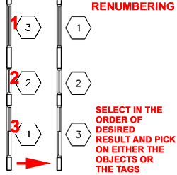
In the Illustration to the left I show that
in order to reverse the order of the three Window Tags, you have to Select
each Tag or Window Object in the order that you want the new increment.
Property Set - use this drop-down list to
select the Property Set Definition Style that you either expect to find already Attached
to your objects or that you expect to Attach while Renumbering. If you don't select
the correct Property Set and don't want to Attach a New Property Set, you will get an
alert message on the command line stating that "The
selected object does not already have the property set" and you will not be
able to renumber that object.
|
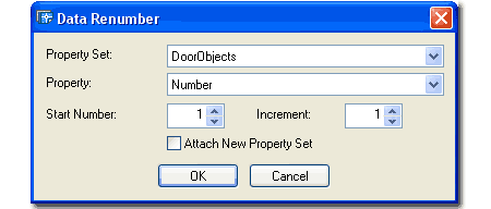
Property - this drop-down list will
probably only offer one default option, "Number", until you really dig into
custom settings for your Schedule Data. This option is tied to the Property Set
Definition Styles and the Name used for Numbered items.
Attach New Property Set - this checkbox
will attach the Property Set selected on the Property Set drop-down list to the objects
that you select for Renumbering. This means that if you know that you want to Add
another more elaborate list of information to the basic set, you can now do it while
Renumbering. In other words, since you are manually selecting your objects,
one-by-one, you might as well take advantage of anything else you can do with Schedule
Data. |
Property Data Format Styles
| Alt.Menu |
Document>
Scheduling> Data Format Styles... |
| Keyboard |
PropertyFormatDefine |
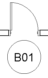 At
the heart of all the Schedule Data is the Property Set Definition Styles but
within those Styles are sub-styles for Formatting and these Style are
located under the Documentation Objects folder in the Style Manager.
These Formatting Styles are listed under the |ab Property Data Formats
section as illustrated to the right. At
the heart of all the Schedule Data is the Property Set Definition Styles but
within those Styles are sub-styles for Formatting and these Style are
located under the Documentation Objects folder in the Style Manager.
These Formatting Styles are listed under the |ab Property Data Formats
section as illustrated to the right.
The Property Data Format Styles control how you want the data or
text in your Schedule tags displayed and formatted. One of these Styles, for example,
is responsible for the way your Door tags start with the number "01". Given that
we not only have preferences for how we like to number our Doors and Windows but what
information we wanted included, you can use the Formatting
tab of the Property Data Format Properties dialog box to Add Prefixes or Suffixes,
control the number of characters, unit type and round off values.
On a Door or Window tag, for example, this is where you can
use a Prefix to specify which floor your tags refer to ( note: you can also
use the Project Based Tags but that
requires that you use the Project Management System). In the
illustration to the right and left I show that I have Copied the default
|ab Number - Object Property Data Format Style and used it to create a
new one that I called |ab Letter_Number - Object and set the Prefix
value to "B". To recreate this type of result, you will need to
modify the Property Set Definition Style as well and set the Format field of
the affected Property Definition Name to any new one you have created.
I will elaborate on this process under the Property Set Definition Styles
discussion below.
GENERAL
Prefix - a letter, number or combination of both that will precede your
tag field. On Doors and Window tags, this could be a letter or number to designate
floor level.
Suffix - a letter, number or combination of both that will
proceed your tag field. On Area tags, this would be something like SF (Square Feet)
or M2 (Square Meters). This is also where you will take care of AutoCAD and ADT's
inability to produce decent metric output; you can use a 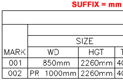 suffix of "mm"
for millimeters on normal measured values. suffix of "mm"
for millimeters on normal measured values.
Undefined - this is what you want stated in a case where
the value is not defined or does not match the parameters set forth by the Style.
Not Applicable - this is what you want
stated in a case where the value does not apply to the specific object.
TEXT
Case - using this drop-down list, you can control the how you want your text
information displayed with respect to upper and lower case characters; As is
( as it was written ) , Upper ( all upper case letters ), Lower
( all lower case letters ), Sentence ( first letter begins with an upper
case and the rest is in lower case letters ) and Title ( first letter of
every word in a sentence is upper case).
INTEGERS
Zero Padding - this controls the number of integers that
can be used for the value field of a tag. On Door and Window tags, for example, this
is where you can limit the numbers to two digits instead of the three on the default tag.
TRUE/FALSE
True - this is where you can specify what will be written when the tag refers to
a True statement; you can, for example, use the single "T", "Yes",
"On", "Active", etc.
False - see comments for True. |
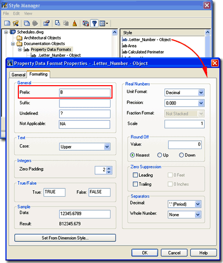
REAL NUMBERS
Unit Format - this is how you can specify what form you want your numbers
in and is just like how you specify dimension unit formatting; you can choose Scientific,
Decimal, Engineering, Architectural or Fractional.
Precision - this is a
round off value.
Fraction Format
- this is only available for architectural and if you plan to export to something like an
Excel Spread Sheet, fancy formatting will not be accepted. Don't worry about it
though, you will be prompted for how to convert them.
Scale -
this is a simple concept with a confusing term so think of this as a
Multiplier ( as in Scale Factor ) that can be used to affect the actual data
collected. You could, for example, set this to 25.4 to report Imperial
measurements in Metric form. Use the Sample area to see how this value
works.
ROUND OFF
Value - this is for floating point
values like .001 and so on.
ZERO SUPPRESSION
Leading - if checked, you won't get 0.5 but simply .5 - not
preferred
Trailing - if checked, you won't get 5.0 but simply 5 - varies
on tolerance
0 Feet - if checked, you won't get 0'-3" but simply
3" - preferred
0 Inches - if checked, you won't get 3'-0" but simply 3' - not
preferred
SEPARATORS
Decimal -
to use you must have Unit Format set to anything other than Architectural or
Fractional. This value controls the decimal separator as opposed to
the whole number separator discussed below. In some European cases, a comma is used where
imperial units would use a period.
Whole Number -
use this set of options to control how whole numbers express every fourth
unit position as in "100,000,000".
Set From Dimension Style... -
here's a novel idea since all of this stuff comes from the Dim Styles anyway. Use
this button to select a loaded Dim Style as the source of these settings. |
|
6Loading Property Set Definition Styles |
6-18 SCHEDULES |
Opening Property Set Definition Styles in the Style Manager
| Alt.Menu |
Document>
Scheduling> Property Set Definitions... |
| |
|
| Keyboard |
PropertySetDefine |
| Links |
Space Styles - for how to create
a Space Style |
For Property Set Definition Styles, you can use the Style
Manager to load, modify, delete and create new Property Set
Definition Styles. The Confusing aspect of Loading Predefined Property
Set Definition Styles is that they are not in a drawing file of their own
but rather part of the Schedule Tables (Imperial).dwg and Schedule
Tables (Metric).dwg files. After you realize where these Styles
are, it becomes logical that they are located together with the Schedule
Styles but they were in a separate file in the past - called
"PropertySetDefs.dwg"
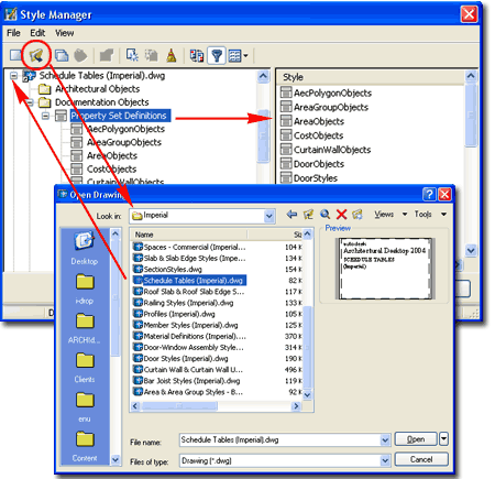
 Illustrated to the right, I show the process of
locating all of the default Property Set Definition Styles within the
Schedule Tables (Imperial).dwg file. Notice that you have to load this
drawing file in the Style Manager Window and then Open the Documentation
Objects folder to locate the Property Set Definitions category. Illustrated to the right, I show the process of
locating all of the default Property Set Definition Styles within the
Schedule Tables (Imperial).dwg file. Notice that you have to load this
drawing file in the Style Manager Window and then Open the Documentation
Objects folder to locate the Property Set Definitions category.
For local installations of ADT, you are likely to find the Imperial
or Metric Schedule Tables Styles in the Styles Folder
as illustrated to the left. The full path to this location may vary but typically it
is as illustrated. On a Network based installation of ADT, these Styles should
be on a captured drive (like "G:\offices standards") or similar location with a
folder name that indicates Styles. Consult your CAD or IT manager if you cannot
locate the Styles Folder. |
 ADT comes with a fairly extensive list of Property Set Definition Styles
covering everything from basic Blocks to Railing Styles. Many of these
Styles are great starting points for custom versions with your own
information added. |
Adding Property Set Definitions to Objects
| Alt.Menu |
Document>
Scheduling> Property Set Definitions... |
| |
|
| Keyboard |
PropertySetDefine |
| Links |
Edit Schedule Data - Add Property Set
- for information on how to Add Data to Objects on an individual basis |
There are basically two types of Property Set
Definition Styles; those designed to work with a whole Object Style and
those designed to work with each Object on an individual basis. In the
simple case of a Door Object, for example, there are some forms of Data that
you might want to track based on the Style while there will be numerous
forms of Data that must be tracked uniquely for each Door Object; such as
Height, Width, Location and so forth.
When you create a Door Style, for example,
you might create one that will represent all low cost interior hollow core
wood veneer doors ( Home Depot Specials, you might say ). Now, it
would make sense to use the Property Data to indicate that all Doors of this
Style are Hollow Core Wood Veneer but it may not make sense to include a
Cost since the sizes will most likely vary. Cost, therefore, is an
example of Data that is better tracked at the Object Level. You could,
however, have an average Cost at the Style Level just to assist in early
estimates.
Illustrated to the right, I show how and
where you can Add Property Sets... at the Style Level of an
example Door Style. Since this Style was created from scratch and not
by copying an existing Style, no Property Sets appear on the Edit
Property Set Data dialog but by using the Add Property Sets button
any Property Set that Applies to Door Styles can be Added. This
means that you can not only Add the default Property Sets but any new ones
that you might want to include for your own Schedules or Spread Sheets. |
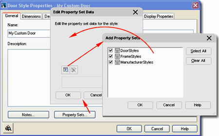
The good news about accidentally forgetting to
add Property Data Sets at the Style Level is that you can always go back an
Add it.
For information on Adding
Property Sets at the Object Level, read
Edit Schedule Data - Add Property Set. |
|
7Property Set Definition Styles |
7-18 SCHEDULES |
| Style Manager - Property Set
Definitions For Property Set Definition
Styles you can use
the Style Manager to load, modify, delete and create new Property Set
Definition Styles.
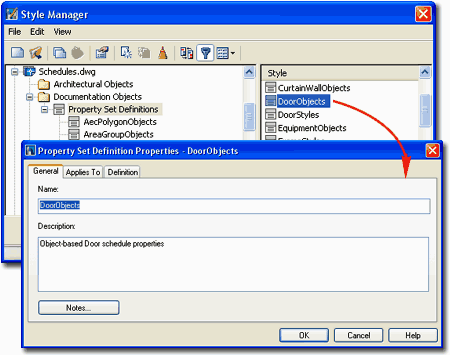
Illustrated to the right, I show the process of
Modifying an Existing Property Set Definition Style:
DoorObjects.
By double-clicking on this or any style, you will invoke the Property
Set Definition Properties dialog box - as illustrated. In the
steps below I will discuss how to make changes to this Style as a basis for
helping you modify other Styles or create your own from Scratch.
The General tab provides access to the Name
and Description fields for a Style; plus access to the attachment of
Notes.
What Are They?
Property Set Definitions are actually the key to the Schedule Data in Schedule
Tables. This is where you get the Schedule Data from when you use the Edit Schedule Data
dialog box to edit existing fields or use the Add... button to find
another Property Set to associate with your selected object. These Styles Collect
Data from known objects and provide fields for user input values to be associated with
specific objects. |
 |
| Property
Set Definition Properties - Applies To tab
If you have already worked with other Definition Styles
in ADT, then you should be familiar with the concept of Applying a
Definition Style to one or more Objects. Basically this is a filter
mechanism that keeps users from doing odd things like tagging Furniture with
Door
 Tags,
for example. The fascinating aspect of this feature is that you can
expand the list of affected or "taggable" Objects so you could include a
Roof in your Window Schedule should you ever need to do such an odd thing -
Actually I have when faced with a skylight problem but that's another story. Tags,
for example. The fascinating aspect of this feature is that you can
expand the list of affected or "taggable" Objects so you could include a
Roof in your Window Schedule should you ever need to do such an odd thing -
Actually I have when faced with a skylight problem but that's another story.
APPLIES TO:
There are two options for this declaration, "Objects" and "Styles
and Definitions", and you must choose carefully. In the
example illustrated to the right I am showing the DoorObjects Property Set
Definition Style which was designed for Door Objects and thus Applies To
Objects and not Styles. For a discussion on the differences, read my
comments for Cost under
Edit Schedule Data - Add Property Set.
Style Based Data is good for automatic data collection and common
information but not good for data that is unique for each object within a
Style Family. It could easily be argued that the DoorObjects Property
Set Definition Style is a poor example of how some Data should be managed -
see the default WindowStyles and WindowObjects for the opposite example.
By checking Object or Object Style Names in
the left-hand pane of the Property Set Definition Properties dialog box, you
set the Filter for those Objects and prevent accidental use of this Data for
other Objects or Object Styles.
|
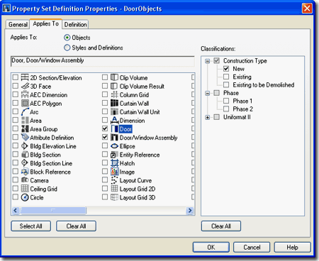
CLASSIFICATIONS:
The list of Classifications will vary depending on the Object or Object
Style Names selected in the left pane and on the Classification Definition
Styles currently available in your drawing file. If you use
Classifications as part of your Applies To settings, you are creating
another level of Filtering that will prevent users from Attaching Data to
some Objects within an Object Style Family.
As an example, you might
think of a set of Doors that have been Classified as "New", "Existing" or
"To Be Demolished". By using the Classification Filter for only one of
those categories, a user will not be able to Apply or Attach this Property
Set Definition to Doors that are not Classified to match the selected
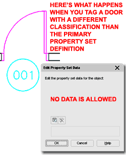
(checked) Filter. This appears like a fantastic feature and in essence
it is but I found that despite the filter, Door and Windows can still be
Tagged; the Property Set Definition cannot be Attached but the Tag will
still hook on to the Door. I would, of course, prefer that you could
not Tag the Door but then this would prevent simultaneous Schedules: one for
New Doors and one for Doors to be Demolished, for example. If you are
interested in exploring this further, make sure to look into using this
Classification system on your Schedules as well because I have found that option often
produces more of what I want than using the filter here. In other
words, I don't use the Classifications Filter as illustrated to the above, I
only show it to demonstrate how it could be used. |
Property
Set Definition Properties - Definitions tab
| Button |
Function |
 |
Add Manual Property
Definition - use this option to create a field for virtually any sort of
typed input like Manufacturer, Color, Cost and so forth. |
 |
Add Automatic
Property Definition - this option extracts data from the Object but can
only extract from a predefined list hard-coded into the Objects such as
Dimensions, Layer or other items that may have been filled in by the
user at the Object or Style Level such as Color and Style Name. |
 |
Add Formula Property
Definition - this option combines the features of the Automatic Property
Definition with mathematical formulas |
 |
Add Location
Property Definition - this option combines the features of the Automatic
Property Definition with a proximity or location detection aperture that
finds additional data from specific Objects that relate to the primary
source of data. An example of this feature is a Door Tag that
reads the Room Number of a Space Object that runs up to the edge of the
Door. The way this works is that you are actually just making a
call to the Property Definition of another Property Set. |
 |
Add Classification
Property Definition - this option combines the features of the Automatic
Property Definition with Classification Definition Style Property Sets
so you can extract data from a Classification as it relates to an
Object. This means, for example, that two Identical Doors
Classified differently could produce different data based on that
Classification. |
 |
Add Material
Property Definition - this option combines the features of the Automatic
Property Definition with Material Definition Style Property Sets so you
can extract data from a Material as it relates to an Object. Like
Classifications, this provides you with the option to extract, for
example, that the Glazing Material is Tempered on a particular Door or
Window. This assumes you go through the trouble of making
different Glass Materials which I just haven't gotten around to yet. |
 |
Add Project Property
Definition - this option combines the features of the Automatic Property
Definition with the Project Management System which has tens if not
hundreds of fields for data on everything from Project Number to Contact
Numbers for team members. See the Project Navigator for access to
the Project Details dialog. |
The Definition tab of the
Property Set Definition Properties dialog box, illustrated to the
right, is where all of the magic for data collection and management occurs.
This subject can get a little overwhelming at first but once you see the
correlation between Property Names, Data Sources, Formatting, Objects and
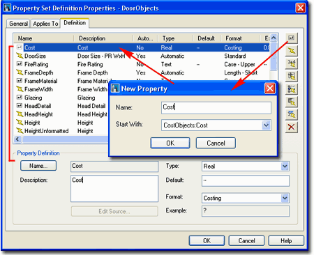
Schedules it gets a little easier to comprehend. Illustrated to the right I show how you can use the
New Property Button to Add a Cost Property by using the CostObjects Property Set
Definition Style as a source to Start With. You don't actually need the
CostObjects Property Set as a source to Start With but it can be useful to save
time in setting the Property Definition Settings such as Type, Default and
Format. In my example to the right, I set the Type to Real numbers, the
Default value to "--" since I don't have a default Cost and the
Format to
"Costing" (if you don't have this Format, create one -
Property Data Format Styles ). |
Adding a Property Definition does not guarantee
that you will find this new field in your Schedule Table. If you want
to include a new Property Definition's data in your Schedule Table, then you
will have to Modify the Schedule Table Style that acquires or extracts it's
data from the current Property Set Definition Style - in this case that
would be the default Door Schedule. See
Style Properties - Columns tab
below for an example of how I added this Cost example to the default Door
Schedule Table Style. |
| The subject of
Adding Property Definitions obviously requires a bit more of a discussion
with some examples and I intend to get to that as soon as I can.
Hopefully you get the general idea from what I have outlined above. |
|
|
8Adding Schedule Tables |
8-18 SCHEDULES |
|
Add Schedule Table dialog box
When adding Schedule
Tables, the Properties
Palette offers a fairly limited list of options but you don't
really need that many. Be aware that the options do change on the
Properties Palette when Modifying an existing Schedule Table.
GENERAL
Style - a drop-down list offering a list of currently loaded
Schedule Styles.
Type TableStyle or use the Content Browser to load other Styles.
Illustrated to the right I show the full list of Schedule Table Styles that
come with ADT in the Imperial Folder.
Scale - this value is derived directly
from the
Drawing Scale and should not be changed unless you have a full
understanding of how this value affects the Schedule Table and Printing
output. It may be unfortunate that you cannot simply add your Schedule
Tables in a Layout at 1:1 scale but then it might be more difficult to jump
between Cells and Objects. Therefore, you typically must Add your
Schedule Tables in Model Space (unless you have data in a Layout) at a Scale
equivalent to the intended Printing Scale and use a Viewport to arrange the
Schedule Table in a Layout.
Automatic Updates - the
automatic features may be a system problem for large drawings with hundreds of symbols.
One example of this would be when you make changes to the size or type of Door or Window;
the schedule will reflect this change automatically. I don't use this feature but
simply update the schedule when I want it updated.
SELECTION
Add New Objects
Automatically - the
automatic features may be a system problem for large drawings with hundreds of symbols.
One example of this would be when you Add a Window Symbol to a new Window; the
schedule will reflect this addition automatically in live mode. I don't use this feature
but simply update the schedule when I want it updated. |
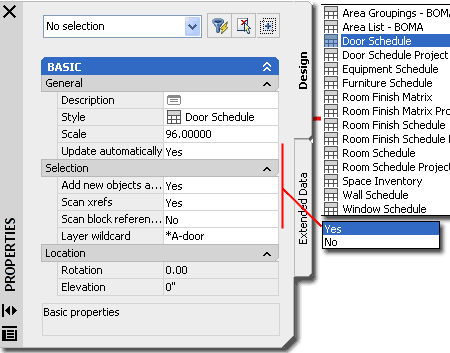
Scan Xrefs - this
is an obvious option of you are creating your Schedule Tables in a separate
file for Schedules and you have Xref'd your drawing files with the Objects
that need to be in the Schedule Table. This is obviously not a good
option of you are creating your Schedule Table in the same file as your the
Objects you are Scheduling and have Xref's for reference purposes only (
such as other Floor Levels ).
Scan Block References -
This option will read Objects within Blocks such as Doors in Lavatory
Layouts that come in the ADT Library. This option could add Objects to
your Schedule Table that you don't want included so exercise caution when
exploring it. Layer Wildcard - this option allows you to
specify Objects by layer. You can, for example, build a Door Schedule for Door
Objects placed on the layer, "A-Door-exterior" or for Doors on the 2nd Floor (
for those crazy enough to work on multiple floors in one file). |
| Adding a Door Schedule Once
you are ready to place your Schedule Table Object (typically in Model
Space), notice that there is a prompt on the command line "Select objects
or ENTER to schedule external drawing:"
If you are adding your Schedule Table to the
active drawing file and not an Xref of a Plan, simply Select the Specific
Object that you want in your Schedule or Select the entire drawing. To
Select every Object I typically type "All". If there are
specific Objects in the Selection Set that you don't want in your Schedule
Table, such as existing Doors, you can use the Layer Wildcard filter on the
Properties Palette, discussed above, to filter them out. If these
Objects are on the same Layer, then you may need to deselect them or employ
other filter mechanisms such as Classifications.
If you are adding your Schedule Table to a
drawing where you are expecting to extract data from one or more Xref files,
then simply follow the instructions by hitting the "Enter" key.
Based on the Drawing Scale, you Schedule
Table should come out at an appropriate size so there should be no need to
resize it; just hit the "Enter" key to get past the two Corner prompts.
Should you need to manually size the Schedule Table, something I don't
recommend, you can use the "Upper Left Corner" and "Lower Right
Corner" command line prompts to size accordingly.
You can check the default text height on the
Scale tab of the Drawing Setup dialog. If you don't
manually resize your Schedule Table, the size will be based on the
Annotation Plot Size x Drawing Scale. This will allow you to create a
Layout Viewport and set a Viewport Scale equivalent to the Drawing Scale
ratio and get a Print with an appropriate text hight.
Notice that some Doors do not have a Mark
number but a question mark ("?") instead. Since I used
the "All" method of selecting Doors for my Door Schedule, I got all of the Doors
without tags too and they will not get Mark numbers or other information until I Tag
them.
|
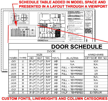 Schedule Table Fonts:
Illustrated above, I show that you can not only control the various lineweights within a
Schedule Table but also the Text Style. By default, ADT will add
the "Schedule" Text Style to your drawing.
Using the Text Style dialog box, you can map the Schedule Text Style to any Font you want.
The problem with fancy fonts is they slow down your machine so you may want to change them
near the end of a project. You can also design Schedule Table Styles
that always use the Text Styles and Heights that you want every time you use
them in different projects - see discussion under
Schedule Styles below. |
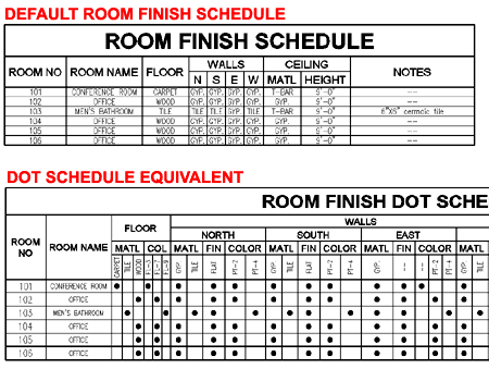
| Adding a Room Finish
Schedule Using a similar
approach to Adding Door Schedule Tables, you can Add other Schedule Tables
such as the Room Finish examples illustrated to the right.
Room Finish Schedule Tables are rather
impressive if you happen to have all of the data filled out for all of the
Space or Area Objects that define your rooms. This can proved to be a
tedious task and one alternative to working on each Object is to Add the
Schedule Table, Select the Objects and then fill in the missing Cells by
using the TableCellEdit command.
The best solution for filling out Room Finish
Schedule Tables is to design Space or Area Objects that already have most,
if not all, of the data completed. For standardized commercial work
this is easier to accomplish than with custom residential work. |
 |
|
9Modifying Schedule Tables |
9-18 SCHEDULES |
Schedule Table Properties
Palette
| Alt.Menu |
Document>
Scheduling> Schedule Properties |
|
|
| Keyboard |
TableProps
or -TableModify |
| Mouse |
Double
pick on Schedule Table Object |
| Links |
Schedule Tables Grips
Points - for a Grips Points on Schedule Tables with Breaks |
 For Modifying
Schedule Tables you can use the Properties
Palette which offers all of the same options as those found when
Adding Schedule Tables plus a number of fantastic options you won't find
anywhere else. For Modifying
Schedule Tables you can use the Properties
Palette which offers all of the same options as those found when
Adding Schedule Tables plus a number of fantastic options you won't find
anywhere else.
GENERAL
Scale - see comments for Adding Schedule Tables. If you change
the printing Scale of your drawing, this is the place to change the scale of
the Schedule Table.
Update Automatically - see
comments for Adding Schedule Tables. The option to turn this feature
On and Off (Yes/No) can be used as a performance control for projects that
make computers run slower.
SELECTION
See Comments for Adding Schedule Tables.
LOCATION
I have commented on these options for most other Objects in ADT and you
should be familiar with them by now. Schedule Tables should be kept at
an Elevation height of zero unless you have a really good reason for
some other value.
EXTERNAL SOURCE
Schedule External Drawing - since you already have the option to
"Scan Xrefs" under the Selection Section, this option seems redundant and
may become something different than an Xref control in the future but for
now, you will need to set both to "Yes" to get Xref Objects in your Schedule
Table.
TABLE BREAKS
Table Breaks provide the means to "break" a Schedule Table in cases
where the schedule is longer than the page you are trying to print it on or
where you want a different arrangement than one long vertical column.
Direction - use this
drop-down list to chose between positioning schedule table segments
vertically (Down) or horizontally (Right).
Repeat Title - use this
Yes/No drop-down list option to include or exclude the main title on your
Schedule Table. |
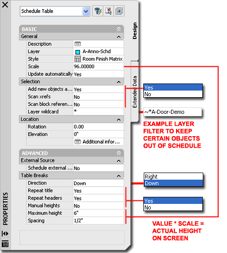
Repeat Headers - use this Yes/No
drop-down list option to include or exclude the headers or column categories
on your Schedule Table. I highly recommend that you include these in
most cases.
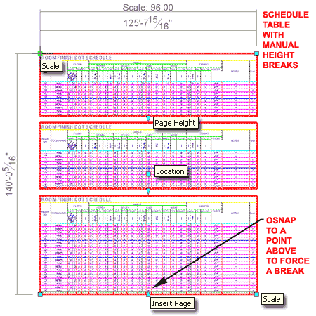
Manual Heights - use this
Yes/No drop-down list option to allow for Manual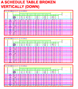 Grip Controlled Break points and Spacing Heights or lock this option out for
Automatic values set below. When setting to Yes, Grip Stretch the
bottom of your Schedule Table up to a point where you want a Break and you
should see the Schedule Table separate at that point.
Maximum Height - use this
value field to indicate the maximum column height allowed before a Break is
to occur. Since numerous other factors, such as Text Height, affect
the total Schedule Table height, use this value as an approximation to be
rounded down. The height must be entered in "real world" units that
are automatically multiplied by the "Scale" value under the General Section.
Spacing - use this value
field to indicate how far apart you want the broken Schedule Table segments.
As with the Maximum Height value, enter this in "real world" units that will
be multiplied by the Scale value.
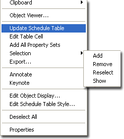
Illustrated to the left I show the
object-specific pop-up menu and the options you have for a Schedule Table Object. In addition
to these options, you will find that you can also do some modifications by
using Grips. |
Update
Schedule Table
| Menu |
N.A. |
 |
 |
| Keyboard |
TableUpdateNow |
| Mouse |
Select
Schedule Table, right-click and Select Update Schedule Table |
|
The Update Schedule Table routine may
be one that you will never use since Schedule Tables can be set to Updated
Automatically but if this "automation" causes a drain on your computer's
performance, you may want to deactivate the Automatic Update and use this
tool instead. In other cases where strange graphic glitches have
occurred for me, I have used this tool much like a Refesh or Regen on
Schedule Tables. |
Edit
Table Cell
| Menu |
N.A. |
| |
|
| Keyboard |
TableCellEdit |
| Mouse |
Select
Schedule Table, right-click and Select Edit Table Cell |
 The
Edit Cell tool provides the option to Select Schedule Table Cells and edit
them directly. You can also Select the entire Schedule Table, by
picking on the outer boarder and edit numerous items at once. The
Edit Cell tool provides the option to Select Schedule Table Cells and edit
them directly. You can also Select the entire Schedule Table, by
picking on the outer boarder and edit numerous items at once.
When you use this tool, notice the command
line options: "Select schedule table item (or the border for all
items), hover for information, or CTRL-select to zoom:" The
Zoom option can be quite useful when attempting to figure out which Object
you are editing.
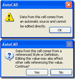
Some Cells cannot be edited because they
acquire their data automatically from the Object itself, such as sizes and
you will need to Modify those Objects directly in order to make the change
in the Schedule Table. Some Cells may produce a warning that Editing
the Data will affect other cells and this simply means that you are editing
Data from the Style Level rather than the Object Level. In other
words, it is okay to proceed but you will probably see a lot of Cells change
to match your single change - see Dialog Alerts to the left.
|
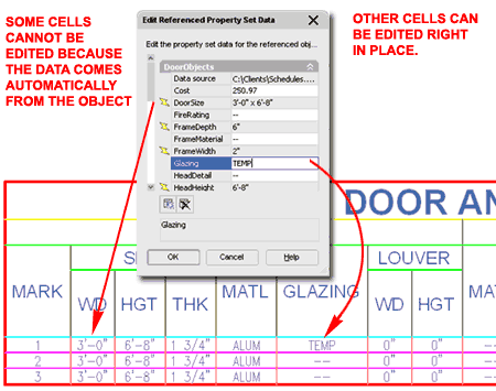
If you want to Edit an entire Column,
Select the Cell Header Text such as the "Glazing" Title illustrated above.
When editing, you may see the words "*varies" in the field you want
to edit and it may even change to a specific value when you pick in the
field but I found that you have to type the value you want, even if it is
already there, and then hit the Enter key to get a whole Column change. |
Add All
Property Sets
| Menu |
N.A. |
| |
|
| Keyboard |
AecAddAllPropSets |
| Mouse |
Select
Schedule Table, right-click and Select Add All Property Sets |
The Add All Property Sets tool serves
as a quick fix for resolving problems with Objects and Object Style that
don't have Property Sets Added for proper Scheduling. You may
occasionally find that there are Objects in your Schedule Tables that
produce the question mark ( "?" ) symbol and that is usually an
indication that there is no data for that Object.
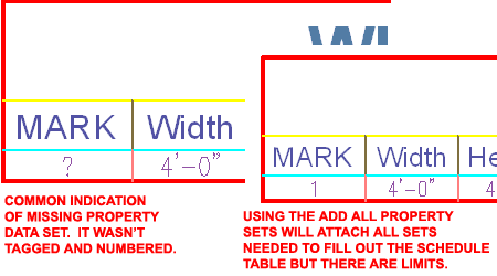
Illustrated to the right I show how an
example Window Schedule has a Window Object that has not been Tagged and
numbered. Because of this fact, the Numbers Data Field of the
WindowObjects Property Set is missing and the Schedule displays a "?".
Using the AecAddAllPropSets command will fix the Data Problem but it
will not automatically number all of the Windows so you would still need to
do that part of the work.
Note:
This tool does not work with Objects inside Xref's. |
 |
Schedule
Table Selection Options
| Menu |
N.A. |
| Keyboard |
TableSelectionAdd |
| |
TableSelectionRemove |
| |
TableSelectionReselect |
| |
TableSelectionShow |
| Mouse |
Select
Schedule Table, right-click, Select Selection and cascade to one of the
options listed above |
The Schedule Table Selection options provide
the means to Add, Remove and Reselect (Add and Remove
together) Objects to be included or excluded from your Schedule Table.
|
For some this is an easy way to
manage Schedule Tables where there is little to differentiate Objects that
are "Existing", "To be Demolished" and/or "Proposed", for example.
Filters and Classifications can be used to manage Objects to be included and
excluded from Schedule Tables but sometimes simply Selecting what you want
is easier - especially for less advanced users. For more advanced
users, this is a great tool to work-around mistakes in Object organization
when there isn't time to run back and fix Layers or Classifications.
The TableSelectionShow
command will highlight the source Object on your screen so you can determine
which Object is feeding the Data to the Selected Cell.
|
|
Schedule Tables Grips
Points
Editing Schedule Tables with Grips is not
only quite limiting but should rarely be done. For Sizes, Schedule
Tables are set by a Scale factor and you can modify the Scale Value on the
Properties Palette. Other Sizes, such as those for Cells, you will
need to work with the Schedule Table Style and set a Fixed Width Cell Size
Override. Illustrated to the right I
show an example Schedule Table with a Manual Height Table Break because this
provides one extra Grip Point: Insert Page. In addition
to the Insert Page Grip which can be used to create manual Table or Page
Breaks, you can use the Page Height to adjust Breaks that have
already been made. |
 |
| 10Schedule Table Styles |
10-18 SCHEDULES |
Style Manager - Schedule Tables
| Alt.Menu |
Document>
Scheduling> Schedule Table Styles... |
 |
 |
| Keyboard |
TableStyle |
| Links |
Loading Schedule Table Styles
- for information on how and where to load the default Schedule
Table Styles |
| |
|
For Schedule Table objects, you can use the Style
Manager to load, modify, delete and create new Schedule Table Styles.
Schedule Table Styles are found under the Documentation Objects folder of
the Style Manager.
Illustrated to the right, I continue the
discussion of adding a Cost Property to Doors by showing how to add the Cost
Property as a Column to the default Door Schedule. Though you may
never use this example, keep in mind that it exemplifies how to Add all
sorts of Property Data to your Schedules.
As with all other Styles in ADT, you can
create a New Schedule Table Style from scratch by using the New Style
button. You can also use Copy and Paste to create a Copy of an
existing Schedule Table Style and use that Style as the source for your new
custom version.
The General tab provides access to the Name
and Description fields for a Style; plus access to the attachment of
Notes. |
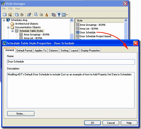 |
| Style
Properties - Default Format tab On the Default
Format tab of the Schedule Table Style Properties
dialog box, you set the primary values for the Text and Symbols in your
Schedule Table. Though this provides only one control for all the text
in a whole Schedule Table, you can set Overrides on the Layout tab Title,
Column Headers and Matrix Headers. Use this tab to set the desired values for
the general body of text within the Schedule Table.
TEXT APPEARANCE
Style - these styles come from the Text Style dialog box so you may
want to create a unique one for your Schedule Table or use the default
Schedule-Data Text Style. Type "Style" on the command line to access
the Text Style dialog box.
Alignment - this should be an obvious
option to control where, in the cell, you want your annotation or numbers.
Height - this value is controlled by the
Drawing Scale so you can type the finished print height and not worry about scaling for
print scales.
Gap - this is the area around your text
and is just another way of saying "distance between cell lines".
Notice that it actually helps to control the Cell Size Height value.
Rotation - here you have two options; one
for Horizontal Text and one for Vertical Text - a very
useful option where you need long descriptions for simple cell values.
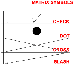 MATRIX
SYMBOL MATRIX
SYMBOL
Symbol - this drop-down list offers four symbol choices: Check, Dot,
Cross, Slash. So far I have only been able to use them for True/False cases
as controlled by the Property Set Definition Style (Property Definition Type)
but there might be a way to use them at other times.
|
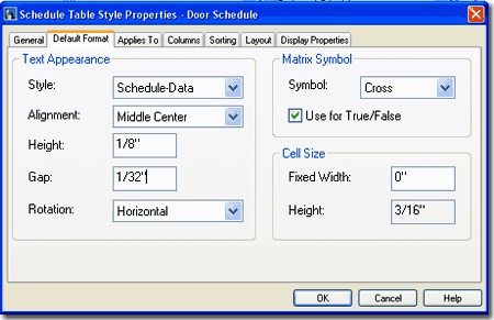 Use for True/False - this checkbox can be used to
have the symbol, selected above, inserted for either True cases or False cases; ADT's
default is to use the symbol for True and not for False. This can be changed on the
Property Set Definition Style dialogue box. If left unchecked, the word True
or False will show up for True and False cases. If you want
something else written like On or Off, etc., go to Schedule Data Format
Styles and change the default values for True and False.
CELL SIZE
Fixed Width - this value, if set to other than zero, will be fixed to
that width. If left at zero, it will automatically be determined by the length of
the value reported to the schedule from the Property Definition Set ( probably a smarter
choice ).
Height - this value is not
accessible because it is just a result of Text Appearance Height + (2 * Gap). So, if you
want it bigger or smaller, simply control the Gap value. |
| Style
Properties - Applies To tab
On the Applies
To tab of the Schedule Table Style Properties
dialog box, you
set the Object Types your Schedule will be reporting on. You can select several
objects or just one since the information put in your Schedule Table is filtered by the
Columns tab.
If you don't know exactly what Object to Apply To, it's
okay to select several. In fact, you can use the Select All button and just let it
have the potential to read all objects but you may find this a mess with more complex
Schedule Tables. You cannot leave it blank, if you Clear All and come back, you will
see that everything gets checked, so you have to have at least one object checked.
Notice that for the default Door and Window Schedule Table Styles, that
Door/Window Assembly Objects have been included. This means that Door
and Window Assemblies could potentially be list in either a Door or Window
Schedule Table ( or even both ). If you Insert Doors or Windows in
your Assemblies, you can actually Schedule them separately from the Door and
Window Assembly.
CLASSIFICATIONS:
The list of Classifications will vary depending on the Object Names selected in the left pane and on the Classification Definition
Styles currently available in your drawing file. If you use
Classifications as part of your Schedule Table Style, you are setting yet
another filter that may exclude Objects within the Type you have chosen in
the left pane. |
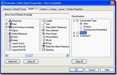
Illustrated above I show the default Door Schedule Table Style and how it is
set to Apply To Door and Door/Window Assembly Objects but I
also show that I have a custom Classification Definition Style that I
used in my current drawing file to distinguish between "New", "Existing"
and "Existing to be Demolished" Doors. By setting
the Classifications to "New" in this example, my Door Schedule will not show
any Doors that have been Classified as "Existing" or "Existing to be
Demolished". Keep in mind
that this is just an example that I have chosen to demonstrate some of the
capabilities of ADT. You do not have to go to such extensive lengths
to create a Schedule Table that only displays new Doors; you can achieve the
same results by simply Selecting the Doors you want in your Schedule at the
time that you create it. Making Schedules from Xref'd drawing files is
another matter, however, since you cannot Select or Deselect Doors within an
Xref - that's where this type of solution becomes invaluable. |
| Style Properties - Columns tab
On the Columns tab of the Schedule
Table Style Properties dialog box, you configure the Columns and
Rows of your Schedule Table by linking Cells to Property Set Data. If
you have ever worked with Excel, this is little more than linking one Cell
to another Cell in another Book where some Product is derived.
Working
with the Columns tab of the Schedule Table Style Properties dialog box can
be fairly complex and I doubt that I can cover all of the possible options
with a couple of screen captures but I can try to provide you with enough of
an overview that you can venture into this realm on your own.
Illustrated to the right I show that I used
the Add Column... button to access the Add Column dialog box
illustrated to the lower right. Once on the Add Column dialog box, I
show that I found the Cost Property Data that I Added to the DoorObjects
Property Set earlier in this discussion. After Selecting the example
"Cost" Property Data, I show that I have a few control options on how I want
this Data presented in my Schedule Table and where I want the Column for
this Data inserted. If you make a mistake on the Column Position or
you simply want to move the Column, you can drag the Column Header to a new
position on the Columns tab.
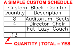 Illustrated
to the left, I show a very simple but useful Schedule Table that
counts furniture blocks and provides a Description
for them. Under the Columns tab, illustrated to the right, you should find
the "Include Quantity Column" checkbox which can be used to tally
such things as the number of seats in an Auditorium. Illustrated
to the left, I show a very simple but useful Schedule Table that
counts furniture blocks and provides a Description
for them. Under the Columns tab, illustrated to the right, you should find
the "Include Quantity Column" checkbox which can be used to tally
such things as the number of seats in an Auditorium.
|
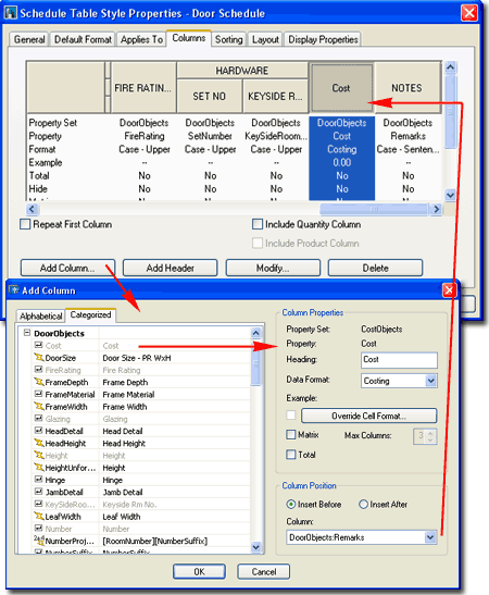 |
| More to come.... |
|
| Style Properties - Sorting tab On the Sorting tab of the Schedule Table
Style Properties dialog box, you can control the sorting order of the
information in your Schedule Table based upon one or more Property Values.
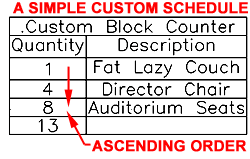 Illustrated
to the right I show the Property that the default Door Schedule Table Style
uses to sort Doors by: Ascending order based on the Tag Number. I also
show how using the Add... button provides access to the Select Property
dialog box where you can select one or more Properties as Sorting Tools; you
could, for example, Sort by Cost. Illustrated
to the right I show the Property that the default Door Schedule Table Style
uses to sort Doors by: Ascending order based on the Tag Number. I also
show how using the Add... button provides access to the Select Property
dialog box where you can select one or more Properties as Sorting Tools; you
could, for example, Sort by Cost.
Illustrated to the left I show how a simple custom Schedule Table has been changed from
Descending to Ascending order based upon the Quantity Values.
Multiple Sort Properties:
For multiple sorting properties, the top Property takes precedence over the lower
properties. In the case of organizing things based on number values and alphabetical
names, the higher Property will govern the lower. A more complex scenario involves
sorting items based on quantity and cost. If the cost of two items is equal, then
the sort order will fall upon the quantity count. |
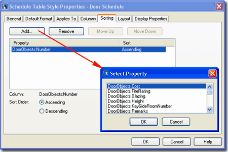 |
| Style Properties - Layout tab On the Layout tab of the Schedule Table
Style Properties dialog box, you provide a Table Title and have
the option to use Overrides on the Formatting of text
and numbers in the Schedule Table. If you recall, the
Default Format tab,
discussed above, was used to set the general Font and Symbol Formatting but
only allowed for one Format Setting. By using Overrides, you can
control how you want other items Formatted.
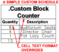 Illustrated to the left, I show that I have
a custom Title for
my example Schedule Table; ".Custom Block Counter" and provided
an Override on the Text Formatting of the Table
Title. Illustrated to the left, I show that I have
a custom Title for
my example Schedule Table; ".Custom Block Counter" and provided
an Override on the Text Formatting of the Table
Title.
If you combine these great options with the Display
Properties for the Component Layers, you can create a rather attractive Schedule Table
with great fonts and lineweights. |
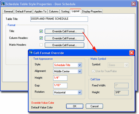 |
| Entity
Display... - Schedule Table
The Display Properties tab of the Schedule
Table Style Properties dialog box, illustrated right, provides access
to line and annotation display controls. Schedule Table objects are
obviously quite different from other typical ADT object types and thus offer a set of options appropriate for a Schedule Table.
Illustrated to the right I show the
Layer/Color/Linetype tab of the default "General" Display
Representation for any Schedule Table Style in ADT. By default you
may find all sorts of Color Settings on this tab but I changed my example to
use more basic Colors to match how I work. Since you cannot use "By
Material" to control how Schedule Tables appear, you will need to use
Colors, Lineweights or Plot Style Tables Names.
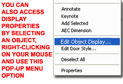 Illustrated
to the left, is another way to access the Display Properties tab; select
the specific object, right click on your mouse
to invoke the object-specific pop-up menu and select Edit Object Display... Just
be aware that when you use this approach, you can actually set an Object Override as
opposed to a Style Override. Object Overrides can be extremely useful because they
allow you to make one Schedule Table appear different from another but can
also be problematic because you cannot control Objects with Display
Overrides from one central source. Illustrated
to the left, is another way to access the Display Properties tab; select
the specific object, right click on your mouse
to invoke the object-specific pop-up menu and select Edit Object Display... Just
be aware that when you use this approach, you can actually set an Object Override as
opposed to a Style Override. Object Overrides can be extremely useful because they
allow you to make one Schedule Table appear different from another but can
also be problematic because you cannot control Objects with Display
Overrides from one central source.
If
your Schedule Table disappears under one or more Display
Configurations, check the Display Representation Sets and look to see
if its Display Representation is Checked; by default this would be the
"General" Display Representation but some offices have custom Display
Representations for their Schedule Table Styles. |
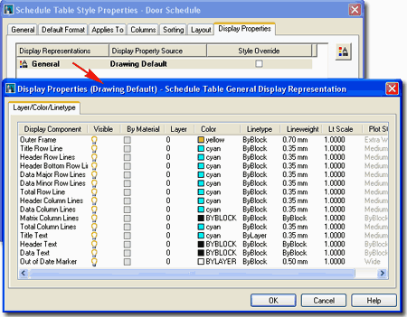 |
| Entity
Properties - Schedule Table - Component Layers
Illustrated to the right I show all but one of
the Display Components that you will find on the Layer/ Color/ Linetype tab
of the
Display Properties dialog box
discussed above.
Not all Display Components are used in
all Schedule Tables. Total Row Line and Total Column Lines
will only appear if you have added a Totals Column to your Schedule
Table Style. Components like Header Bottom Row Line and Data
Major Row Lines offer the option to control specific row lines uniquely
but you don't have to set their Properties uniquely if you don't want them
to appear any different from the Data Minor Row Lines. The Data
Major Row Lines will appear at intervals of five rows and I could find
no way to alter that setting (I believe it is hard-coded that way).
I still have not found an example of the Out of Date Component
Display Component so that's why I don't have a graphic example for that
Color. |
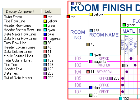 |
| 11Exporting Schedule Tables |
11-18 SCHEDULES |
Export Schedule Table dialogue box
| Menu |
N.A. |
 |
 |
| Keyboard |
TableExport |
| Mouse |
Select a
Schedule Table, right-click and Select the Export... pop-up menu option |
| Links |
|
For Exporting Schedule Table Data to
an external format, you can either Export a Table in the current drawing
file or create a new one based on the Input settings on the Export Schedule
Table dialog box illustrated to the right.
To Export an existing Schedule Table
that is in the current drawing, simply Select it, right-click and Select the
Export... option off the Object-specific pop-up menu. This method will
no allow you to use the Input options should you decide to change your mind
about what to Export.
To Export a new Schedule, use the
TableExport command which will allow you to use the Input area of the
Export Schedule Table dialog box. The options under Input are
identical to those found on the Properties Palette when Adding a Schedule
Table. If you use the "Use Existing Table" checkbox, you
will be queried to "Select existing schedule to export" and the
result is identical to Exporting a Selected Schedule Table as discussed
above.
OUTPUT
Save As Type - you only have three choices
here so pick one and go. I find that using Excel works rather well but if you have
other programs that you want to import your data into, you may need to use the Tab or
Comma delimited formats The three formats are: Excel ( .xls), Tab delimited and
Comma delimited.
File Name - this is just the common Save
As... file name and location option so provide a name and a location on your system or
Network and go.
INPUT
Use Existing Table - use this checkbox if you want the
option to select your Schedule Table from any existing Schedule Tables on your screen; a
common and logical approach.
|
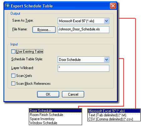 Schedule Table Style - this and the
options below are only available when you uncheck the Use Existing Table. If you do
not plan to use an existing table, you can now Export one based on any loaded Schedule
Table Styles. This means that you now have a way to export out to Excel information
that you may not want a Schedule Table for but you do want a Spread Sheet for.
Layer Wildcard - see comments for
Add Schedule Table dialog box.
Scan Xrefs - see comments for
Add Schedule Table dialog
box.
Scan Block References - see comments for
Add Schedule Table dialog
box. |
| Export Schedule Table to Excel Example
When I did my first Export of a nicely formatted Schedule Table, I got the
Format dialog box alert below and panicked. If you get this dialog box
too, it is probably because of how you have Formatted your Fractions.
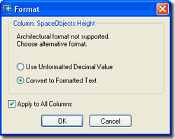 As illustrated to the right, by setting the Format to Convert
to Formatted Text for All Columns, the resultant Spread Sheet was just fine.
For Metric, you may find that you will need to use the Decimal Value option but it
would be unusual to have this problem with metric or decimal numbers. As illustrated to the right, by setting the Format to Convert
to Formatted Text for All Columns, the resultant Spread Sheet was just fine.
For Metric, you may find that you will need to use the Decimal Value option but it
would be unusual to have this problem with metric or decimal numbers.
I'll leave the formatting in Excel up to you. As you
can see, this Exported Door Schedule example will not fit on an A-size sheet of paper. |
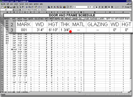 |
| 12Schedules - Customizing and Tricks |
12-18 SCHEDULES |
|
Slabs and Room Tags
If you tend to use Slab Objects for floors,
you may want to tag them with Room or Room Finish Tags but you may find that
you can't since these Tags, by default, only apply to Space and Area
Objects.
Illustrated to the right is a simple step
that you can take to change these Tags so they will work on
Slab Objects. By using the
PropertySetDefine command you can access styles like "RoomObjects"
and "RoomFinish" and change their Applies To setting as
illustrated to the right.
Once you have changed the Applies To setting
to apply to Slab Objects, you will find that the Tag will now react to Slab
Objects and function much like it does for Space and Area Objects. |
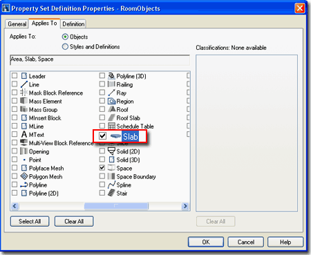 |
| Adding Sill
Height to Window Schedule Tables
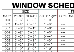 Illustrated
to the left is a simple solution to a common request and that is the need to
include the Sill Height ( similar for Head Height) in the default Window
Schedule Table. Illustrated
to the left is a simple solution to a common request and that is the need to
include the Sill Height ( similar for Head Height) in the default Window
Schedule Table.
Modify the Window Schedule Table Style as
discussed in this chapter and find the Columns tab as illustrated to the
right. Use the Add Column... button to access the Add Column dialog
box.
On the Add Column dialog box, illustrated to
the lower right, Type a Heading title for your Schedule Table Column (
something like "Sill Height"), set the Data Format for an appropriate way to
display your heights ( such as Length - Long ). Find and Select the
SillHeight Property Definition on the Categorized tab under WindowStyles
as illustrated to the right. Use the Column pull-down list to Select
the Name of the closest Column relative to where you want this Sill Hight
Column to be placed and then use the Insert Before or Insert After radio
button to set the side. If you make a mistake on the position of the
Column in the Table, just use your cursor to drag the Column Header to the
new position.
|
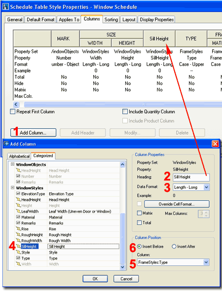 |


 Scheduling
is a topic that could be a book in itself and it is definitely a subject
that I continue to learn about. Therefore, I consider this chapter or
"part" a work in progress that I hope to add to over the next year or so.
 In
order to Add a Schedule Table to your drawing or project, you must load a
Schedule Table Style. Unlike numerous other Object Styles, there is no
default "Standard" Schedule Table Style.
 work with
the Project Browser and Navigation System. What that means is
basically just another way to collect more automatic data such as Door Tag
numbers tied to Floor Levels using Project Based Tags. The whole
Project File System is new to ADT 2004 and in its infancy so don't feel
compelled to use it unless you find it beneficial for managing floor levels.


 Adding
Door and Window tags is fairly easy when you have just a few to
deal with but when you have 50 or more it becomes rather tedious.
There is no automatic way to tag a whole series of openings in some logical
order; you actually have to Select each Object and tag them one at a time in
the order you want the numbers to ascend. Should the order change, ADT
offers a
 Adding Object tags is fairly easy but
often disappointing because the values or information you get in the tag, automatically,
usually are simple defaults unlike the automatic numbers for the Doors and Windows.
 By
reading the titles for the various Room and Finish Tags, you can probably
guess at the Object Styles these Tags were designed for. By default
then, Room, Space and Room Finish Tags only work on
Area and Space Objects.
 Adding Wall tags is a matter of choosing
one of the two Wall tag types and dragging it into your drawing.
 Both
the Imperial and the Metric Content Folders now contain Area tags
and they are basically identical. For both Imperial and Metric use, the Area tag is
based upon a BOMA standard indicating the Room Number, Room Name, Net Usable Area (NUA)
and Net Rentable Area (NRA). There are two versions of the same tag where the
"Scale Dependent" one will automatically change size for Low, Medium and High
Detail Display Configurations ( rather handy for those presentation plans on A-size paper
).
 Schedule
Tags are usually Multi-View Blocks that have been configured with
the


 The
Object specific pop-up menu for Tags will offer the option to
Release the Tag or Set another Object as illustrated to
the left. Generally, I have not found either of these option very
helpful because if you desire to remove a Tag, you can just Delete it and if
you wish to transfer a Tag to another Object, it is better to use the
Tagging process whereby Property Data is automatically attached to the
Object. If you attempt, for example, to Set one Door tag to another
Door that has no Data, that Tag will Anchor but it will not transfer any
Data.
 Objects
do not have to be Tagged in order to have Property Data Sets attached to
them so when you wish to Modify Data Fields, you can either Select the
Object or the Tag ( if one exists ). As discussed earlier, not all
Data can be modified since it may be derived automatically from the Object
and/or Object Style but there are numerous Data Fields that require manual
input at some point in a project.
 Illustrated
to the left I show an example of how you might want to work with some
Multi-View Blocks that you want to tally or include in a Schedule. If
this example Sofa was tagged, I would probably not need to Add and Property
Sets manually, but if I don't want to Tag it or I want to Add other Property
Sets, this option is fantastic. And, since MvBlocks are not Style
Based, you can't Add the Property Sets at any other level anyway.

 When
you need to reorder Tags that use sequential numbers such as those for Doors
and Windows, you can use the Data Renumber dialog box illustrated to the right.
The primary problem I have with this tool is that the user has to do all of
the hard work by not only selecting all of the Tags but doing it in the
proper order.
 At
the heart of all the Schedule Data is the Property Set Definition Styles but
within those Styles are sub-styles for Formatting and these Style are
located under the Documentation Objects folder in the Style Manager.
These Formatting Styles are listed under the |ab Property Data Formats
section as illustrated to the right.
 suffix of "mm"
for millimeters on normal measured values.


 Tags,
for example. The fascinating aspect of this feature is that you can
expand the list of affected or "taggable" Objects so you could include a
Roof in your Window Schedule should you ever need to do such an odd thing -
Actually I have when faced with a skylight problem but that's another story.


 For Modifying
Schedule Tables you can use the Properties
Palette which offers all of the same options as those found when
Adding Schedule Tables plus a number of fantastic options you won't find
anywhere else.
 Grip Controlled Break points and Spacing Heights or lock this option out for
Automatic values set below. When setting to Yes, Grip Stretch the
bottom of your Schedule Table up to a point where you want a Break and you
should see the Schedule Table separate at that point.
 The
Edit Cell tool provides the option to Select Schedule Table Cells and edit
them directly. You can also Select the entire Schedule Table, by
picking on the outer boarder and edit numerous items at once.


 MATRIX
SYMBOL

 Illustrated
to the left, I show a very simple but useful Schedule Table that
counts furniture blocks and provides a Description
for them. Under the Columns tab, illustrated to the right, you should find
the "Include Quantity Column" checkbox which can be used to tally
such things as the number of seats in an Auditorium.
 Illustrated
to the right I show the Property that the default Door Schedule Table Style
uses to sort Doors by: Ascending order based on the Tag Number. I also
show how using the Add... button provides access to the Select Property
dialog box where you can select one or more Properties as Sorting Tools; you
could, for example, Sort by Cost.
 Illustrated to the left, I show that I have
a custom Title for
my example Schedule Table; ".Custom Block Counter" and provided
an Override on the Text Formatting of the Table
Title.
 Illustrated
to the left, is another way to access the Display Properties tab; select
the specific object, right click on your mouse
to invoke the object-specific pop-up menu and select Edit Object Display... Just
be aware that when you use this approach, you can actually set an Object Override as
opposed to a Style Override. Object Overrides can be extremely useful because they
allow you to make one Schedule Table appear different from another but can
also be problematic because you cannot control Objects with Display
Overrides from one central source.


 As illustrated to the right, by setting the Format to Convert
to Formatted Text for All Columns, the resultant Spread Sheet was just fine.
For Metric, you may find that you will need to use the Decimal Value option but it
would be unusual to have this problem with metric or decimal numbers.

 Illustrated
to the left is a simple solution to a common request and that is the need to
include the Sill Height ( similar for Head Height) in the default Window
Schedule Table.