| 1Slabs & Slab Tools - Access |
1-10 SLABS & SLAB TOOLS |
Slabs and Slab Tools toolbars
How do I get this toolbar?
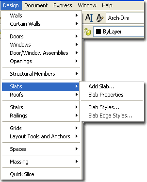
You can also acquire access to some of these commands from the Alternate Design
pull-down menu. From the Design pull-down menu, pick Slabs
> and cascade to their respective command options - see image below,
right. |
 |
 |
| Slabs and Slab Tools pull-down menu
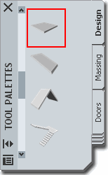 The Slab
Object is basically little more than a copy of the Roof Slab Object and thus you will find
a lot of similarities. At times you may find the jargon for Roof Slabs a bit
confusing since they are based on Roof Slabs; terms like Soffit and Fascia but if you
think in terms of a flat or low pitched Roof then you should have no problems working with
this Object. The Slab
Object is basically little more than a copy of the Roof Slab Object and thus you will find
a lot of similarities. At times you may find the jargon for Roof Slabs a bit
confusing since they are based on Roof Slabs; terms like Soffit and Fascia but if you
think in terms of a flat or low pitched Roof then you should have no problems working with
this Object.
For some designers the Slab may not be a necessary Object
in your Construction Documents since Foundation work and Framing work is often handled by
Structural Engineering and their Construction Documents. Though I might rely on
separate structural information to be included with my final construction documents, I
still use the Slab Object to help create footing outlines, patio, sidewalk and street
edges, floor framing envelopes and so on. Slab Objects are great in Sections and
provide ceiling and floor surfaces for presentation renderings.
On the command line, you can type "Slab"
when you want access to many of the Slab creation options. For direct access to an option
within the Slab command-line menu, you can type the primary command plus the option you
want direct access to. For example, if you want to Add a Slab, you can type "SlabAdd"
or if you want to Modify a Slab, you can type "SlabProps" or
"-SlabModify".
Below is the command line read-out for "Slab":
Command: SLAB
Roof slab [Add/Convert/Modify/Properties/Styles/Edit/edGes/Hole]: |
On the command line, you can now type "SlabEdit"
when you want access to many of the Slab Editing options. For direct access to an
option within the Slab Edit command-line menu, you can type the primary command plus
the option you want direct access to. For example, if you want to Trim a Slab,
you can type "SlabTrim"
Below is the command line read-out for "
Slab Edit":
Command: SlabEdit
Edit [Add vertex/ Remove vertex/ Miter/ Trim/ Extend/ Cut/ Xcut/ Boolean]: |
| Spaces toolbar
Illustrated to the right is the Spaces
toolbar and I show this because Spaces can also be used for Slabs and in many cases appear
to be a better solution for this object type. Space objects come with a Ceiling
option, have Space Tags for Area Calculations and can be created from
existing Wall objects. |
 They can also be set to automatically read Stair objects
and create an appropriately sized hole by using the Space Interference tool. What
Spaces do not have, is the option for Edge Styles but if this is not something you need, I
suggest you try working with Space objects before settling for Slab Objects. They can also be set to automatically read Stair objects
and create an appropriately sized hole by using the Space Interference tool. What
Spaces do not have, is the option for Edge Styles but if this is not something you need, I
suggest you try working with Space objects before settling for Slab Objects.
Personally, I don't use Space but that is
because I typically use Slabs as Concrete Foundations and take advantage of the ability to
attach a Perimeter Footing detail. |
| 2Loading Slab Styles |
2-10 SLABS & SLAB TOOLS |
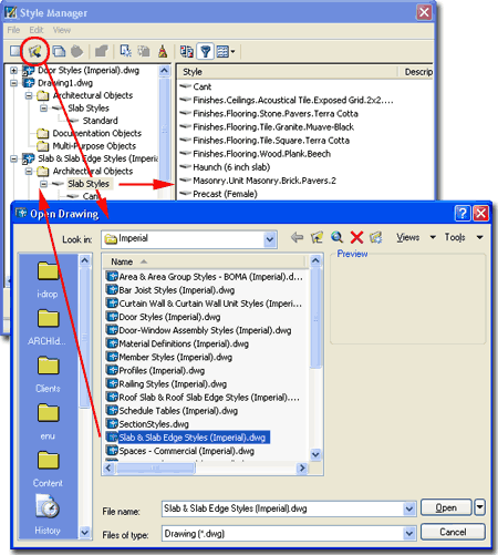
| Opening
Slab Style templates in the Style Manager
ADT comes with a short list of predefined
Slab Styles that you can access through the Style Manager or by using the
Content Browser
Window ( Architectural Desktop Design Tool Catalog... Roof Slabs and Slabs ).
Since Slabs are often rectangular shapes with a bit of thickness, you may not even
need any of these predefined Styles but you will certainly want to learn how to create
your own so you can, at least, name them.
 The Slab
Object is often used by designers as a generic all-purpose 3D Massing Object for
things like table tops, ceilings, streets, sidewalks and so on. This practice may or
may not be a good approach to solving problems in ADT but as long as you are aware of how
this object functions and displays, you should feel comfortable using it as creatively as
you can. For some design problems, however, I find using other Object Styles a bit
superior; such as using Wall Styles for countertops and full cabinetry. The biggest
attribute the Slab Object offers is the option to create custom Slab Edges - discussed
below. The Slab
Object is often used by designers as a generic all-purpose 3D Massing Object for
things like table tops, ceilings, streets, sidewalks and so on. This practice may or
may not be a good approach to solving problems in ADT but as long as you are aware of how
this object functions and displays, you should feel comfortable using it as creatively as
you can. For some design problems, however, I find using other Object Styles a bit
superior; such as using Wall Styles for countertops and full cabinetry. The biggest
attribute the Slab Object offers is the option to create custom Slab Edges - discussed
below.
|
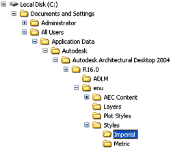
 For
local installations of ADT, you are likely to find the Imperial or Metric
Slab Styles in the Styles Folder as illustrated to the
left. The full path to this location may vary but typically it is as
illustrated. On a Network based installation of ADT, these Styles should be on a
captured drive (like "G:\offices standards") or similar location with a folder
name that indicates Styles. Consult your CAD or IT manager if you cannot locate the
Styles Folder.
Slab
& Slab Edge Styles (Imperial).dwg
Slab
& Slab Edge Styles (Metric).dwg |
| 3Adding Slabs |
3-10 SLABS & SLAB TOOLS |
Add Slab - Properties Palette
| Alt.Menu |
Design> Slabs>
Add Slab... |
 |
 |
| Keyboard |
SlabAdd |
The Slab Properties Palette
offers a fairly simple list of options that should be self-explanatory if you think in
terms of a 3D planar object. The primary settings you need to be concerned about are
the Style, the Mode, Thickness, Justification
and Perimeter edge. The steps for creating a Slab
involve tracing the perimeter shape you expect to use as a Slab form and this means that
you can draw a Slab Object much as you would a Polyline. Another great way to create
a Slab is to use the SlabConvert
command to convert a Closed Polyline shape into a Slab.
The Direction setting is of little consequence unless you
are planning on providing a Slope Value at
later point in time.
Style - a drop-down list offering a list
of currently loaded Slab Styles. See Loading Slab Styles for how to
Load predefined Styles. Though you can easily make due with the "Standard"
Slab Style, I highly recommend creating a new Slab Style with a unique name, even if it's
as simple as the "Standard" Style. I also recommend using different Slab
Styles wherever Slabs could potentially be different because this will allow you to
accommodate such design differences at a later date should changes come about.
Mode:
Direct - this method allows you to pick the perimeter points for your Slab at the
exact 3D points in space where you want your Slab to sit. This means that if you
pick points along the base of a set of Walls that have the same plate height, you will get
a perfectly flat Slab. If you want a Slab at a slope, you will have to pick points
that define the slope; this is why the Slope options are not accessible.
Projected - this method projects the Slab from the points you select and
is really more of an option that applies to Roof Slabs. However, given that you
could accidentally OSNAP to some odd 3D Point in space when tracing the shape for a
Perimeter Slab, I find this option the best because of you set the Slope to zero you will
get a perfectly level slab regardless of the points you pick. Notice that when this
option is active, there are more settings available on the Properties Palettes - see
illustration, right.
In both the Direct and Projected Modes, the first two
points picked establish the base or front of the slab much like how you get the fascia
when you create a Roof Slab.
Thickness - Slab thickness.
 Vertical
offset - this value field offers the option to raise or lower a Slab in
the Z-axis along its Pivot Point. This is more of an option you would expect to use
for Roof Slabs but can be applied to Slabs that need to slope for drainage or other needs. Vertical
offset - this value field offers the option to raise or lower a Slab in
the Z-axis along its Pivot Point. This is more of an option you would expect to use
for Roof Slabs but can be applied to Slabs that need to slope for drainage or other needs.
Horizontal offset -
this value field offers the option to shift a Slab back and forth in the XY Plane relative
to the Pivot Point. This is also more of an option you would expect to use for Roof
Slabs where you may trace the exterior of a Wall but want the Pivot Point at the inside.
Justify - Top, Center, Bottom
and Slopeline are designed to work with the Direct Mode only. Since Direct Mode
allows you to pick the specific 3D points that define a Slab and its slope, the
Justification options allow you to determine where the Slab should be positioned ( along
the z-axis ) relative to those picked points. This is much like deciding to create a
Slab based upon the Top, Bottom or Centerline along a Curb ( for a Roof Slab, it's
like measuring against a single Rafter). Slopeline is determined
by the Offset Thickness value on the Design Rules tab of a Slab's Style.
Base Height - the height from
Z=0 along the Z-axis up to the bottom of your Slab. Projected Mode Only
Direction - this option
affects the direction of your Slab when you use the Ortho Close button
and only works if you use Ortho Close after having picked a second point. The second
point establishes the front of your Slab thus allowing ADT to calculate a Left or Right
direction of "closure". The size is based on the length of the first side.
|
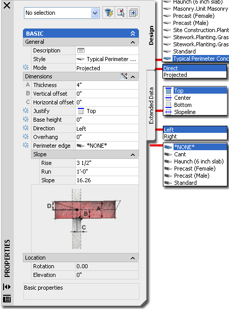 Overhang
- the distance from the insertion point ( where you pick ) out to the Slab's edge ( not
including any edge detailing, curbs, etc. ).
Perimeter edge - this
drop-down list provides access to Slab Edge Styles which can be used to create such things
as curbs, footings or joints. In order to use these you must first create a
SlabEdgeStyle.
Rise - change in Y-axis.
Projected Mode Only
Run - change in X"-axis.
Projected Mode Only
Slope - use this value field
to specify a slope angle if you don't know the rise and run. If you specify the rise
and run, the Slope Angle will be calculated for you. You can use the Properties
Palette to set the Slope after creating a Slab as well. Projected Mode Only
Note:
Observe the options on the Command line.
Specify next point or [STyle/ MOde/ Height/
Thickness/ SLope/ OVerhang/ Jusify/ MAtch/ Undo/ Ortho close/ Close]:
Ortho Close - if used after
picking a second point this button will create a rectangular Slab based upon the dimension
of the first two points ( basically a square with extra for soffit, etc. as per the Style
). The Direction of the Slab will be based upon the direction
established by your second picked point and the Direction buttons ( see Direction
description ). If used after picking three or more points this button simply
calculates what it will take to create an orthogonal closure from the last point picked
relative to the first point picked.
Close - only available if
three or more points have been picked and simply closes a Slab shape to form a polyhedron
much like Close on a Polyline. |
| Add Slab - Direct Mode & Projected Mode When Adding Slabs, you may find the Mode and Direction options a little
confusing so I have illustrated the difference to the right by using the Ortho Close
technique after drawing the first two points for the two example Slabs.
The Direct Mode method of Adding a Slab
assumes that you know the pitch by the virtue of the 3rd point you pick. If you
don't pick a 3rd Point in Space that happens to be higher on the Z-axis than the 2nd
point, there will be no slope change. When you use the Ortho close command line menu
option you will always get a level slab as illustrated to the right. You can use the
Ortho close option after picking the first two points for the front or pivot point of the
slab.
This method can also be very frustrating if you are
attempting to create a flat Slab by OSNAPping to points around existing
objects in ADT. At times, one poorly OSNAPped point can result in a
sloping Slab and thus you may find the Projected Mode more desirable for non-sloping
Slabs.
The Projected Mode method of Adding a Slab
works much like the Roof routine and allows you to specify the Slope and Base Height
before picking your points. This means that you can pick points along the base of
existing Walls, Wall Footings, Columns and so forth and have the Slab begin at the height
( Z-axis ) you desire with a slope according to your rise and run or angle
input. Just like the Direct Mode method, the first two points will establish
the Fascia. The 3rd point will establish the direction in which you want the Slope.
This method is easier to use than Direct Mode.
1 - this point establishes the insertion point of your Slab
so if you want a Slab on top of your plate, you cannot pick at the bottom of your
Walls. This is also where the Pivot icon will be established. |
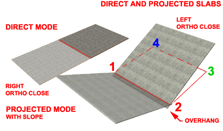
2 - this point establishes the Fascia ( yes, fascia ) length
and Slab orientation with respect to the Fascia. Once selected, you can use the Direction
Arrows to flip the Slab to the Right or Left of these
two points. In order to take advantage of the Direction Arrows, you must use
the Ortho Close button; moving on to pick more points will disable the effect of
using the Direction Arrows because a 3rd point will establish the final direction ( as
well as slope).
3 - once you have moved on to a 3rd point, the Direction Arrows are
no longer valid but you can now use both Ortho Close and Polyline
Close to quickly complete your Slab.
4 -> - once you have moved on to 4 or more points, Polyline
Close should work rather well at any point to simply connect the last point
picked with the first. Ortho Close, however, will not work unless
it can create two additional edges; one from where you last picked and one to create an
orthogonal edge off of the 1st point picked. |
Convert
to Slabs
| Menu |
N.A. |
 |
 |
| Keyboard |
SlabConvert |
| Links |
Slab Properties - Edges tab |
| |
FacetDev - this
variable can be set to control the facetting of curved slabs when Converted from curved
Plines. Set before converting. Lower numbers = better curves. |
The Convert to Slab tool can be used to
convert Plines and Walls to Slabs. In my own use,
I have found that converting Plines often produces a better result than using Walls or
even Adding by picking points around a perimeter. Because the Pline object is a 2D
object that conforms to the UCS and the first point picked, it can be a more reliable
object to create Slabs from.
Tips on Converting:
The Convert to Slab routine was designed to convert one or more Wall objects into a
Slabs This means that you can Select one Wall object and derive a square Slab based
upon the length of that Wall object or you can Select a whole set of Walls and derive
either numerous individual Slabs or one Slab from the enclosure formed by those Walls.
In order to derive a clean internal Slab surrounded by Walls, the Walls must form
the enclosure perfectly and not extend beyond the enclosure.
Inevitably, you will Convert a Pline or Walls into a Slab
only to discover that it is positioned at the wrong elevation. I find that this is
particularly true when converting Walls to Slabs but you can fix the problem by using the Slab
Properties... tool and changing the Z - insertion point on the Location
tab of the Slab Properties dialogue box. |
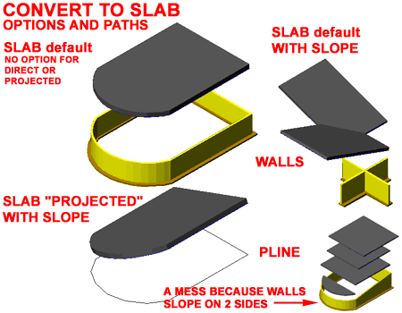 The Pivot Point
on closed Pline shapes occurs at the first point picked to create the Pline and the slope
is established by the direction of the second point. If the second point is an Arc,
the slope will be established by the direction of the Arc but won't slope off of the Arc. |
| 4Modifying Slabs |
4-10 SLABS & SLAB TOOLS |
Modify Slab - Properties Palette
| Alt. Menu |
Design> Slabs>
Slab Properties |
 |
 |
| Keyboard |
SlabProps [-SlabModify] |
| Mouse |
Double pick on a Slab Object
with the left mouse |
| Links |
Tool Palettes - for information on setting
Defaults within the icon buttons for faster productivity |
For Modifying Slabs you can use the
ubiquitous Properties Palette which will offer most of the same options
and settings found on this Palette when Adding Slabs. One of the more interesting
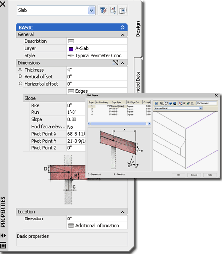
and useful options you will find on the Properties Palette is the Edges dialog,
illustrated right, which will allow you to work on each edge.
 Style - allows you to
change the selected Slab to any other Slab Style currently loaded in your drawing file. Style - allows you to
change the selected Slab to any other Slab Style currently loaded in your drawing file.
Slope - you can input Rise and Run numbers
that will automatically calculate an Angle for you or you can specify an Angle.
Rise - Run - Angle - see Add Slab dialogue box above.
Thickness - this option will not be
available if it has been set as "Has Fixed Thickness" under the Design Rules tab
of the Slab Style.
Pivot Points - if you are working with
Sloped Slabs, you may need to adjust the Pivot Point to assist in better control. If
you wish to set all three points with on OSNAP action, use the "-SlabModify"
command instead.
Note:
Notice that there is no option to change the Justification here. And, you won't find
this option on the Slab Properties dialog box either. This can prove to be a really
irritating issue, especially when you are learning how to use this routine.
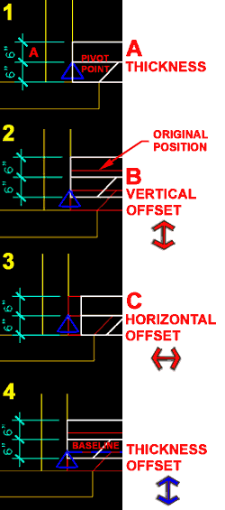
On the Defaults tab of the Slab
Styles dialogue box, illustrated to the right, you will find a graphic that can
be a little confusing when attempting to match the letter with the lettered check boxes
and value fields.
A - Thickness - is the actual
Slab mass thickness as illustrated by the letter "A". The question is, do
you include finishing materials or set it just for the framing (lumber) dimension.
I prefer to work with the framing sizes when not not using the Slab as concrete.
|
B - Vertical Offset - this
value basically moves the Slab up and down parallel with the wall or perpendicular to the
ground but can be confusing when mixed with the Thickness Offset value on the Design Rules
tab.
C - Horizontal Offset - this
should be an easy one to comprehend; you are just moving the Slab back and forth on the
plate line.
D - Slope - this value
becomes the default slope when using the Add Slab dialogue box and will be indicated by
blue text fields.
E - Perimeter Edges -
custom Edge Styles that are basically profiles attached to your Slab's edge. The
graphic can be a bit confusing since you may often work directly off of the F -
Pivot Point and not an adjusted E - Baseline that moves as a
result of working with B - Vertical Offset.
F - Pivot Point
- is illustrated in the graphic on this tab but has no settings here.
New Edge Style button
- use to create a new Slab Edge Style on-the-fly for complex or simple edge
conditions. You may simply want an overhang of a given distance associated with this
Slab Style. If you don't want a style for the overhang, then use the SlabModify command
to add an overhang or use SlabProperties.
In both cases, go to the Slab Properties - Edges tab
of the Slab Properties dialogue box. |
| Slab Properties - Dimensions tab
 On the Dimensions tab of the Slab
Properties dialogue box you can override the Style settings by specifying unique
values for the selected Slab. On the Dimensions tab of the Slab
Properties dialogue box you can override the Style settings by specifying unique
values for the selected Slab.
A - Thickness - is the actual
Slab mass thickness as illustrated by the letter "A". For Concrete it may
be easy but for Wood Floors you may want to add Sub-Flooring material to your Slab
Thickness.
B - Vertical Offset - this
value basically moves the Slab up and down parallel with the wall or perpendicular to the
ground but can be confusing when mixed with the Thickness Offset value on the Design Rules
tab.
C - Horizontal Offset - this
should be an easy one to comprehend; you are just moving the Slab back and forth on the
plate line ( the fascia or 1st two points picked )
D - Slope - use to change the
slope. Adjustment or change in slope occurs around the Pivot Point as established
upon creation of the Slab or by adjustment on the Pivot Point value fields. The
Pivot Point can also be modified directly on the Modify Slab dialogue box. |
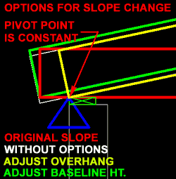
Hold
Fascia Elevation When Changing Slope - a check box option for holding the Fascia
Elevation fixed on the Vertical axis. Use "By Adjusting Overhang"
when you are trying to keep the Slab fixed to the Pivot Point and the fascia aligned ( the
price is that the overhang distance will change ). Use "By Adjusting
Baseline Height" when you want to keep the same exact fascia and overhang
but are willing to drop or raise the Slab down to achieve this result ( the price is that
the slab moves away from the pivot point ).
Pivot Point - this is
the strange blue triangle that constantly changes size when you zoom in and out. You
can manually type in X, Y or Z values to reposition this slope control point but it might
be easier to use the Pivot Point button on the Modify Slab dialogue box. The Z-axis
value is a good place to look though, to verify that your Slab is sitting at the correct
height.
E - Slab Baseline - you may
notice this strange gray value that is in the graphic illustration but not accessible on
either this tab box or its matching equivalent on the Slab Styles dialogue box. The
Baseline is established by the original information used to generate the Slab; e.g., the
point picked to make a Slab. When you Grip edit a Slab you get access to this
component. It can be thought of as a reference point between the original Slab
perimeter and consequent dialogue box changes, such as an overhang. When you Grip
edit though, the Baseline also stretches. |
| Slab Properties - Edges tab
On the Edges tab of the Slab
Properties dialogue box, you can assign overhang values, curbs, cants, footing
haunches and positive or negative edge seams. If you are in a hurry to fix something
on a Slab object, this may work well but for peace of mind you may want to manage this
type of information through a Slab Edge Style instead - that's my recommendation. If
you modify a Slab's Edges here, they will override the settings assigned through the Slab
Edge Style; i.e., the two can co-exist even though they may contradict each other.
There are all sorts of nasty problems that you can get
yourself into working with Edge Styles so I will attempt to save you some  trouble by
outlining as many of them as I can here. trouble by
outlining as many of them as I can here.
The easiest Edge Style to work with is the *NONE*
option which is just a line. Using *NONE* does not mean that you can't be creative
though. You can still have an Overhang, Plumb or Square Orientation and an Angle of
cut with respect to the Plumb or Square cut - see comments on Slab Edge Styles -
Defaults tab.
Using an Overhang value for all edges
other than the Baseline ( usually Edge 1 and the edge established by the first two points
picked when creating a Slab) edge seems to be the only way to actually get an
overhang. I have attempted it many times with a Slab Edge Style and the overhang
never comes through so you may have the same experience. This means that you will
have to use this technique for all overhangs except the Baseline one where the Slab Edge
Style does work. If you find this commentary confusing, consider that when you grip
stretch a Slab's Edge, you are not creating an "overhang" but simply making the
Slab longer or shorter. An "overhang" has to do with a relationship
between the Slab Edge and its fascia - look for distinctive Slab Edge line and this will
become far more clear. Of course this subject has more relevance with Slabs
and their relationship to plates than Slabs. |
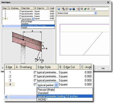 Orientation
- there are two edge types to choose from, Plumb and Square. A square cut on a Slab
is perpendicular to the slope and a plumb cut is perpendicular to a level plane ( or level
floor ).
Angle - the angle off of the
Orientation allows you to have a 30 degree slope off a Plumb cut ( 90 - 30 = 60 degrees ),
for example. You can also set an angle off of a Square cut and with the right number
simply re-create a Plumb cut from a Square cut. This is also where any unusual Slab
Cut angles are stored if you combine the UCS icon with the Slab Cut tool.
As mentioned above, any settings you make here
will override those set for the Slab Style and you can actually do something as crazy as
assign an Edge Style with an overhang value but change the overhang value here.
Doing this type of editing may really cause confusion down the road. There is no
control to avoid this from happening. |
Edit
Slab Edges
| Menu |
N.A. |
 |
 |
| Keyboard |
SlabEdgeEdit |
| Mouse |
Select Slab, Right Click,
Select Edit Edge/Faces... and Select the Edge(s) you want to Edit. |
| Links |
Slab Properties - Edges tab |
The Edit Slab Edges offers you direct
access to the Edges of any Slab Object so you can Modify or Assign new Edge conditions.
Though you can Select more than one Edge before entering the Edit Slab Edges
dialog, this tool is best suited for individual Edge Work where identifying a specific
edge on the Slab Edges dialog ( illustrated above ) is too time consuming. See
discussion on Slab
Edges for more information about the options and settings offered on this
dialog. |
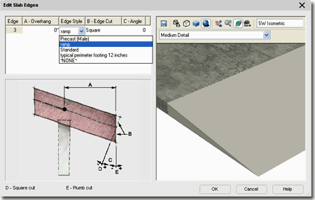 Illustrated above I show
that I have selected one Edge of an example Slab so I could used the Edge Style drop-down
list to pick a custom Slab Edge Style that I created earlier. This custom Slab Edge
Style was set as a Fascia and based upon a triangular Profile to form a concrete ramp.
You cannot select edges of
different Slabs. |
| 5Slab Style Properties |
5-10 SLABS & SLAB TOOLS |
Style Manager - Slabs
| Alt.Menu |
Design> Slabs>
Slab Styles... |
 |
 |
| Keyboard |
SlabStyle |
For Slab objects, you can use the Style Manager
to load, modify, delete and create new Slab Styles.
Though you can easily create New Slab Styles from Scratch
using the New button, you may want to use the Copy/Paste
technique instead because it is far easier to Modify Settings of an existing Object Style
than it is to create one from Scratch. In some cases, you may even miss specific
settings that can come back to haunt you much farther down the road on a project - things
like Display Representations or Data for Schedules.
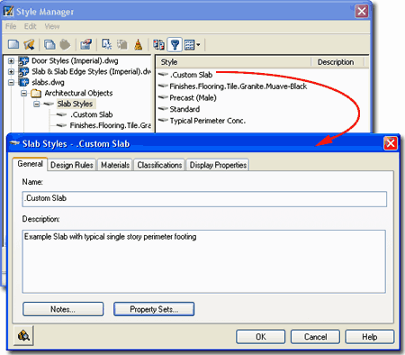
Illustrated to the right I show the process of creating a New
Slab Style that I have Named "Custom Slab". By double-clicking
on this new style, I show that I have also activated the Slab Styles Properties
dialog box where all of the custom settings can be made for the size, shape and look of
this particular object style.
The General tab provides access to the Name
and Description fields for a Style; plus access to the attachment of Notes
and Property
Sets. |
 |
| Slab Styles
- Design Rules tab
On the Design Rules tab of the
Slab Styles dialog box, illustrated to the right, you will find a checkbox that
locks the A - Thickness value field on the Properties Palette and two
Thickness options.
Has Fixed Thickness - check this box to
lock in a Slab Style's thickness value so that it can't be changed except through the
Style. When you check this to fill in a value for Thickness, you will also be
deactivating the A - Thickness value field on the Properties Palette.
Thickness - use this value field to set
the Fixed Thickness value. |
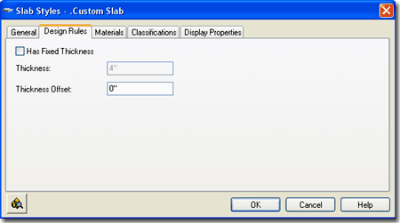
Thickness Offset - use this
value field to control the Baseline position of a Slab relative to the Pivot Point and
measured perpendicular to the slab plane ( i.e., same as thickness ). This does not affect
the Pivot Point like B - Vertical Offset does; i.e., the pivot point
remains fixed at the original insertion point unless otherwise modified. When you
modify this value you also reposition the vertical origin of the Thickness Value (somewhat
pointless), Horizontal Offset and Vertical Offset allowing you to make adjustments in a
triangular fashion; e.g., move a Slab from 3 units up perpendicular to the slope
(Thickness Offset), over 2 units (Horizontal Offset) and down 2 units (Vertical Offset). |
| Slab Styles - Materials tab
The subject of Materials is one of the
most expansive and confusing topics in Architectural Desktop because it requires a
complete comprehension of the product in order to take full advantage of this feature;
from object styles to display representations. This subject will be discussed under Part 1 - Display
and in the Presentation eGuide.
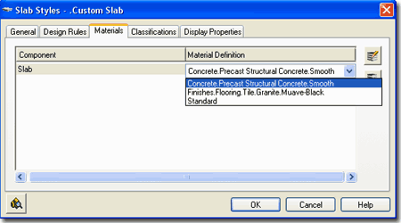
Illustrated to the right I show that Slabs will offer
one predefined Component ( Slab ) and that the Material
Definition Name will be set to "Standard" when you create a Style from
scratch. If you have imported any of the Architectural Desktop Slab Styles from the
Object Style Library, you should find that you will be able to use the Material
Definitions that come with those objects - as illustrated to the right where I am
selecting Precast Smooth Concrete.
Though you are not required to use Material Definitions in
Architectural Desktop, you are likely to find it difficult to avoid using them since most
of the predefined Styles use them. Materials have thrown a monkey wrench into the
whole Display System because they can actually take over control of how your linework
appears in Plan View for Construction Documents ( discussed below under Display Properties
). The best thing to do when learning about Material Definitions is to match how
most of the predefined Slab Styles have been configured; i.e., reverse engineer the ADT
Styles. |
 Though you are not required to use Material
Definitions in Architectural Desktop, you are likely to find it difficult to avoid using
them since most of the predefined Styles use them. Materials have thrown a monkey
wrench into the whole Display System because they can actually take over control of how
your linework appears in Plan View for Construction Documents ( discussed below under
Display Properties ). The best thing to do when learning about Material Definitions
is to match how most of the predefined Slab Styles have been configured; i.e., reverse
engineer the ADT Styles. |
| Slab Styles - Classifications tab
The subject of Classifications is
thankfully no where near as complicated as that of Materials so the only real question you
will need to consider is if you need to use them. Classifications offer another way
to separate Object Styles into categories that can be used in Schedules
and even in Display Representation Sets ( as "Show"
or "Hide" ).
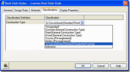
Illustrated to the right I show that I have one Classification
Definition ( see Format pull-down menu) with a list of Classification
Names or Types. Generally you will not have any options on this Tab but if
you have created at least one Classification Style that has been set to "Apply
To" Slab Styles, you will be able to use it here. The range of use is really up
to your imagination but it is fairly obvious that Classifications can be quite handy in
Schedules. This topic will be discussed further under Part 18 - Schedules. You
can also read a bit more about how to create Classification Definitions in Part 1 -
Display. |
 |
| Slab
Styles - Display Props tab
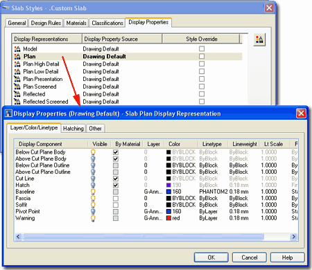
The Display Properties tab of the Slab
Styles dialog box, illustrated right, provides access to the display
characteristics of the components of your Roof Slab objects; from Visibility to Cut Plane
Height overrides. This is also where you would go to have Slabs change color or
Materials, for example, when you switch from one Display Configuration to another.
See the discussion on Slab Display Properties below for more information on this subject.
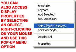 Illustrated
to the left, is another way to access the Display Properties tab; select
the specific object, right click on your mouse
to invoke the object-specific pop-up menu and select Edit Object Display... Just
be aware that when you use this approach, you can actually set an Object Override as
opposed to a Style Override. Object Overrides can be extremely useful because they
allow you to add hatch patterns or change colors of any single object within a Style
Family but they can also be problematic because they lock you out from more centralized,
Style level, controls. Illustrated
to the left, is another way to access the Display Properties tab; select
the specific object, right click on your mouse
to invoke the object-specific pop-up menu and select Edit Object Display... Just
be aware that when you use this approach, you can actually set an Object Override as
opposed to a Style Override. Object Overrides can be extremely useful because they
allow you to add hatch patterns or change colors of any single object within a Style
Family but they can also be problematic because they lock you out from more centralized,
Style level, controls.
|
 |
| Slab - Display Properties
- Component Layers 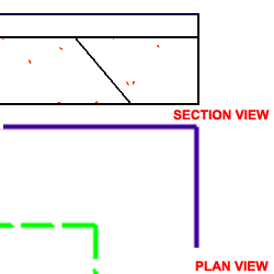 Illustrated
to the right I show how you can do some minor changes to the Plan Display
Representation of a Slab Style to achieve a more "AutoCAD-like"
level of control over the Color, Linetype, Lineweight
and so on of certain Components. By removing the By Material
checkmarks from the Below and Above Cut Plane Body Display Components, you can use the
ByBlock setting to acquire the freedom to set the Color by Layer or by manual override. Illustrated
to the right I show how you can do some minor changes to the Plan Display
Representation of a Slab Style to achieve a more "AutoCAD-like"
level of control over the Color, Linetype, Lineweight
and so on of certain Components. By removing the By Material
checkmarks from the Below and Above Cut Plane Body Display Components, you can use the
ByBlock setting to acquire the freedom to set the Color by Layer or by manual override.
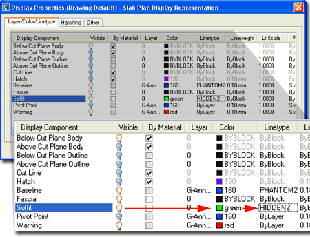
Illustrated to the left and right I show that I have
attached a Soffit Profile to my Slab example and altered how it appears in Plan View by
setting the Soffit Display Component to a unique Color and Linetype ( Hidden2 ).
Read below under Slab Edge Styles to
learn how to attach Profiles. |
 |
| 6Slab Display Properties |
6-10 SLABS & SLAB TOOLS |
| When working with the Display
Properties of Slab Objects, you may soon discover that most of them are more appropriate
for Roof Slab Objects than Floor Slabs. The Slab Object is basically a derivative of
the Roof Slab instead of a completely new Object Type and thus you may find that it does
not really deliver on the features you would expect for something like a concrete slab.
One of the more frustrating aspects of working with the Display Properties of this
object is that you often cannot get the Slab Edge Styles to display as you typically would
for Construction Documents; Fascias, for example, often don't display at all in Plan View
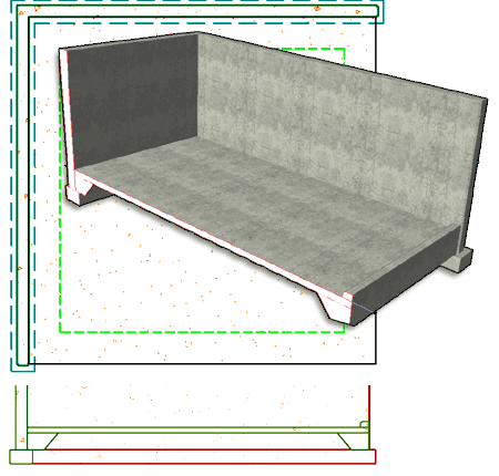
when they are used as a Curb. Illustrated to the
right I show a few mixed design options for a Slab and a Wall Style with a "T"
base footing. Though you can add a "T" footing to a Slab as an Edge Style,
using a Wall Style should prove to be far more appropriate. What I do show as a
viable footing option is a typical perimeter slab edge using the Soffit option. I
also show a curb condition that can either be part of a Soffit Profile or as a separate
Fascia option.
For me, getting a Slab to look correct in Plan View for
Construction Documents is the most important task and then I worry about the Section View.
From the Section View, I typically use the 2D Linework as a rough sketch that I
detail manually using AutoCAD tools and commands. |
 |
Slabs in
Plan
| Menu |
Format> Display
Manager... |
 |
 |
| Keyboard |
DisplayManager |
| Keyboard |
DisplayProps [Attach] |
| Mouse |
Select Object, right-click,
select Edit Door Style... or Edit Window Style... or Edit Object Display... |
| Links |
Part 1 - Display - Object
Display Properties Overview - for more information on how to access the Display
Properties of this Object. |
Continuing the focus on the Plan View for Slabs,
you may find some of the Display Components a bit misleading. The Below and Above
Cut Plane Display Components were designed to work with slopping slabs such as those used
for Roofs and thus may not apply to your floor Slab designs at all. You may need to
read up on the Roof Slabs Part in this guide to see some example but the principle of
Above and Below Cut Planes is basically tied to how a sloped slab passes through a cut
plane in space leaving some portions below and others above.
At the most elementary level, you can affect the display of
Slabs through at least one Layer; like A-Slab, for
example. At the Style level you can affect the physical dimension
of a Slabs thickness and the vertical offset of the that thickness but nothing more.
This leaves the majority of options for display with the Display Properties (
accessed either through the Object, Object Style or the Display Manager ).
Illustrated to the right I show a slightly modified version
of the default "Medium Detail" Display
Configuration which uses the "Plan" Display
Representation for most Objects. In order to illustrate how a slab
perimeter footing might look in Plan, I used a Slab Edge Style as a Soffit
condition which I show in a dashed green line. I also show the Pivot Point Object
just in case you come across this horrible little square that used to drive me crazy in
earlier releases of ADT ( notice that it is turned off by default now ). |
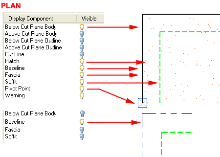 In the second illustration, I show what the Baseline
Display Component looks like and what other Display Components you may need to
turn Off in order to see it. It's not that I think you may use this Display
Component as much as you may want to know which one produces the odd linetype. You
see, the odd thing here about these Display Components is that they can all be On at the
same time so you may see some of them through the linetypes of others.
One of the more confusing aspects of working
with the Slab Object is how the Materials affect the Display Representations. In the
example above, for example, the "Below Cut Plane Body" Display Component does
not really need to be on since the Cut Line or Fascia could produce the same results but
only the "Below Cut Plane Body" has a Material assignment that produces the
stipple effect for the Slab surface. See section below for information on how to
work with the Hatch Display Component. |
| Slab Below
the Cutting Plane
 If
you have read the Roof Slab Above and Below the Cutting Plane discussion in Part 8, you
should comprehend how the Cutting Plane Height relates to Roof Slabs but Slabs or Floor
Slabs, as one might call them, is another matter with its own Cut Plane issues.
Since the default Global Cut Plane Height ( 3'-6" Imperial or 1400mm
Metric) was designed for Walls, Doors, Windows and so forth, it may not be the ideal
height for your Slabs and thus this may be one of the first settings you will need to look
into to get better display results. If
you have read the Roof Slab Above and Below the Cutting Plane discussion in Part 8, you
should comprehend how the Cutting Plane Height relates to Roof Slabs but Slabs or Floor
Slabs, as one might call them, is another matter with its own Cut Plane issues.
Since the default Global Cut Plane Height ( 3'-6" Imperial or 1400mm
Metric) was designed for Walls, Doors, Windows and so forth, it may not be the ideal
height for your Slabs and thus this may be one of the first settings you will need to look
into to get better display results.
The default Slab Styles that come with ADT defer to the
default Global Cut Plane Height and thus use the Below Cut Plane Body Display Component
for the Plan View display. For the most part this solution works rather well,
especially since it can be controlled "By Material" which allows for easier
control over Hatch Patterns. However, if you prefer to think in terms of an actual
cut through your Slab Object, you can set a manual Cut Plane Height and not use the Above
or Below Cut Plane Display Components.
Illustrated to the right I show two example Slab Styles and
what they look like with the default Display Properties and how some changes in those
Display Properties can create better results. Be aware that what I show is not
necessarily the best solution for your work but more of an example of how different
settings produce different results. If you do not wish to deviate far from the
default settings, you don't have to. You may never need to set a Cut Plane Override,
for example but it is good to know that you can.
|
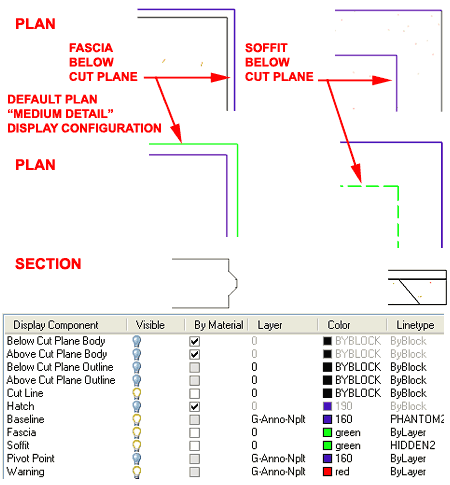 For both examples to the right I have set the Cut
Plane Height to zero and turned the Visibility of all the Above and Below
Cut Plane Display Components Off. Because the protruding "male"
edge on the precast slab example was attached as a Fascia Profile, it is controlled by the
Fascia Display Component. Because the perimeter footing haunch was
attached as a Soffit Profile, it is controlled by the Soffit Display Component.
By cutting the Slab with an adjusted Cut Plane Height, the Cut Line
now becomes an active Display Component controlling the portion of the Slab that is
actually cut ( much like with Wall Objects ). The Baseline Display Component is
probably something that you would want to turn Off, especially if it affects the printing
of your Slabs. |
| Slab Above the Cutting
Plane Sometimes you may have a mixture of
Slab Objects at ground level (at the Cut Plane) and above ground level (above the Cut
Plane) for such things as mezzanines or walkways. At times like this, it becomes
desirable to have the slabs that are above indicated by a dashed linetype.
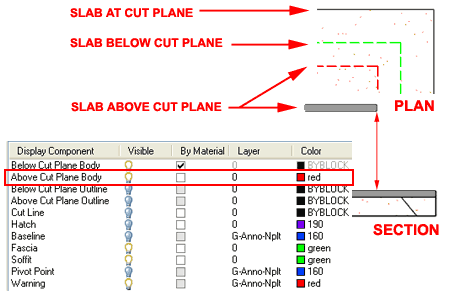
Illustrated to the right I show one of many solutions that
you might wish to employ to have Slab Objects above the Global Cut Plane
display differently than those at or below the Global Cut Plane.
For my example, I simply took advantage of the "Above Cut Plane Body" Display
Component by making it Visible, removing the By Material setting so I could set the Color
and the Linetype ( not shown) to meet my personal preferences ( red and dashed ).
Notice that I have turned the Visibility Off for many of the Display Components that I do
not want to interfere or overlap my primary Display Components.
Note:
Remember that you don't need to be a rocket scientist to overcome some of the obstacles in
ADT's Display System so if you can't figure things like this out or just don't have the
time to work on it, you can always work with AutoCAD options to solve the problem.
You can, for example, create a "A-Slab-Abov" Layer Name, set it to Dashed and
Change Slab Properties to this new Layer. |
 |
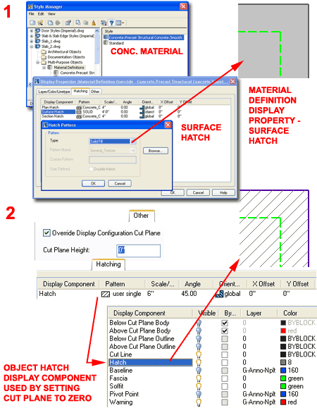
| Slab Hatch in Plan
As with most other objects in ADT, you can control the
Hatch Component for one or more Display Representations by working with the Material
Definition's Display Properties. Using this technique can be one of the most
powerful methods for manipulating the Display of Objects since you typically only need to
make one change to one Material to affect many objects. However, working with
Materials can also be quite confusing so you may just want to use the more traditional
method of working directly with the Hatch Display Component.
1
In the illustration upper right, I show that I
have used the Style Manager to locate the "Concrete.Precast Structural
Concrete.Smooth" or equivalent Material Definition and activated one of several
Display Representations to change the "Surface Hatch" Display Component on the
Hatching Tab to "Solid". Using this technique for one or more Display
Representations, like "General Presentation" will allow you to quickly change
all Slab Surface Hatching.
2
In order to use the Hatch Display Component for Slab Objects,
you must first understand that Hatch Display Components only appear when the Cut Plane
actually cuts through the object you want Hatch across. This means that the Global
Cut Plane typically will not produce a Hatch Pattern and you must use the Other Tab to
"Override Display Configuration Cut Plane" and set the "Cut Plane
Height" to zero (plus or minus depending on your slab thickness and offsets).
Once you have reset the Cut Plane, you can turn Off the Visibility for the Above and Below
Display Components but turn On the Visibility for the Cut Line and the Hatch Display
Components. In addition to this, you can now use the Hatching Tab to set and control
your Pattern.
Note:
This trick does not work well with the Above Cut Plane Slabs since it overrides the Global
Cut Plane. You could still use this trick but as an Object Display Override - best
to avoid these whenever possible. |
 |
| Slab Hatch in Section
|
For
2D Sections of Slab Objects, you can use the Material Definition Style's Display
Representation Properties to work on the Section Hatch Display
Component. For this Display Component, you can use just about any Hatch Pattern and
Scale but I did find one pattern that did not work: Solid. This appears to be a bug
in the software but you can work around this problem by using the 2D Section/Elevation
Styles to control how you want the Shrinkwrap Hatch (turned Off by
default) - see Part 15 - Sections for more information on this topic. |
| 7Slab Edge Styles |
7-10 SLABS & SLAB TOOLS |
Style Manager - Slab Edges
| Alt.Menu |
Design> Slabs>
Slab Edge Styles... |
 |
 |
| Keyboard |
SlabEdgeStyle |
| Links |
Slab Properties Palette - where they are set on
the Slab Properties Palette. |
For Slab Edges Styles,
you can use the Style Manager to load, modify, delete and create new Slab
Edge Styles.
Since Slab Edge Styles are rather simple and don't have
Display Property settings, starting from Scratch when making a new one is as viable as
using the Copy/Paste option that I recommend for most other Object Styles.
Assigning Materials is probably the biggest obstacle you will have to deal with when
working with the Slab Edge Styles dialog box.
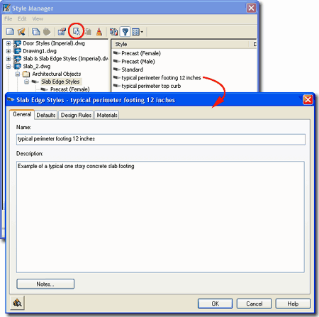
Illustrated to the right, I show the process of creating a New
Slab Edge Style that I have Named "typical perimeter footing 12 inches".
By double-clicking on this new style, you will invoke the Slab
Edge Styles dialog box - as illustrated.
The General tab provides access to the Name
and Description fields for a Style; plus access to the attachment of
Notes but no Property Sets since these will be attached to Roof Slabs. |
 |
| Slab Edge
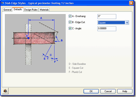
Styles - Defaults tab On the Defaults
tab of the Slab Edge Styles dialog box, you can set an overhang distance,
a plumb or square cut and any angle for the cut. Be
aware that these settings only apply to Fascias and only when you
pre-assign a Slab Edge Style to a Slab Style; this can only be done as an Icon
Property on the Tool Palettes. When Adding Slab Edge Styles to a Slab that
has already been created, these settings will be ignored but can be set as part of the
Slab's Edge Settings. If this sounds like gibberish, it does have an element of that
since this is more of a legacy option that made more sense in earlier releases of ADT.
A - Overhang - this will set an Edge Slab
Style overhang distance measured from the pivot point out. If you specify the actual
Overhang value you want on a particular Slab Style here, you can use it to control the
Overhang of a Slab Style by pre-assigning this Edge Slab Style as a Property on the Tool
Palette.
B - Orientation - a drop-down list
offering a Plumb or Square joist cut on the tail ends. Plumb will give you a cut
perpendicular to the ground ( or parallel to the wall ). Square will give you a cut
perpendicular to the joist slope. See comments for Overhang.
C - Angle - use this value to create any
angle cut you want. These angles work in conjunction with the Orientation so you can
create a 45 degree cut off of a Plumb cut. You can also use positive or negative
degrees where negative degrees cut the rafters back on the bottom. Positive degrees
cut the rafters back at the top. See comments for Overhang. |
 Note:
A word of caution - be really careful about
working with the C - Angle value on the Defaults tab and also working with the Angle value
on the Edges tab of the Slab Properties Palette. You can spend hours trying to
fix a cut angle on the Slab Edge Style when the angle is actually being controlled on
the Slab Properties
Palette.. |
Slab
Edge Styles - Design Rules tab
| Links |
Profiles - for how to create Profiles |
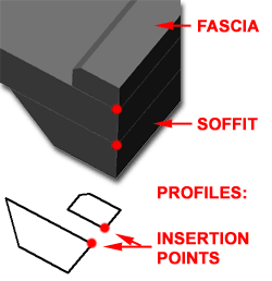 The Design Rules tab of the
Slab Edge Styles dialog box holds all of the settings that create the amazing
Fascia and Soffit results. Since Soffit and Fascia are not the normal terms applied
to Slabs but rather Roofs, you should feel free to be creative about the terms Fascia and
Soffit and how they actually apply to your Slab Edges. The Design Rules tab of the
Slab Edge Styles dialog box holds all of the settings that create the amazing
Fascia and Soffit results. Since Soffit and Fascia are not the normal terms applied
to Slabs but rather Roofs, you should feel free to be creative about the terms Fascia and
Soffit and how they actually apply to your Slab Edges.
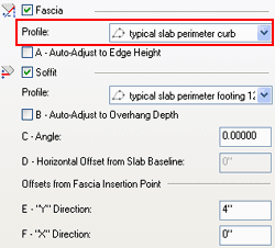
Fascia - on/off. This term can be a
little confusing when relating to Slabs instead of Roofs. I typically think of
Fascias with respect to Slabs as something to be used on top or on the outer edge.
There are two problems with the Fascias on Slabs: you don't have Y and X position controls
and they don't show up in Plan Views ( for flat non-sloping Slabs) unless you display
Model information. If you want a Fascia to serve as an Edge component, use an upper
left or right corner as the insertion point on your Profile. Fascias can also be turned on
or off on the Display
Properties Layer/Color/Linetype tab.
Profile
- drop-down list for selection of any currently loaded Profiles. Though you
can use any profile you will want one designed for the right task. See discussion
below.
A - Auto-Adjust to Edge Height - check box
(on/off). If checked the size of your Fascia Profile will automatically be
determined by the Slab Thickness as determined by a Plumb or Square cut. The scale
maintains aspect ratio so your fascia profile grows or shrinks in both X and Y directions
simultaneously.
Soffit - on/off. Though a soffit typically
implies something below a Roof or Slab, you can use it as something on top of a Slab.
I mention this because I have found that Soffits display with no problems in Plan
View and thus this technique may be your solution for curbs ( such as shower curbs
discussed under Customizing and Tricks ). Use the E - "Y" Direction to
control vertical placement of Profile. Soffits can also be turned on or off on the Display
Properties Layer/Color/Linetype tab.
 Profile - drop-down list for selection
of any currently loaded Profiles. Though you can use any profile you will want one
designed for the right task. See discussion below. Profile - drop-down list for selection
of any currently loaded Profiles. Though you can use any profile you will want one
designed for the right task. See discussion below.
|
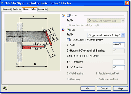 B -
Auto-Adjust to Edge Overhang Depth - check box (on/off). If checked
the size of your Soffit Profile will automatically be determined by a number of various
controls; primarily the distance from the Slab Baseline to the Fascia. You can make
changes to the size and position of the Soffit Profile by working with D -
Horizontal Offset from Slab Baseline and F - "X"
Direction. The scale maintains aspect ratio so your Soffit profile grows or
shrinks in both X and Y directions simultaneously.
C - Angle - pivots the Soffit
Profile or line ( if you use "Standard" ) up or down from the outer bottom
corner of the Slab. This is an interesting option for a simple chamfer cut, try
something like -15 degrees with a "Standard" Soffit Profile.
D - Horizontal Offset from Slab
Baseline - this will move the Soffit Profile out and away from the Slab Baseline
or in ( by using a negative number ). You can use this to compensate for a Baseline
that isn't on the outside edge of a Wall, for example. This will affect the Soffit
Profile scalar size if Auto-Adjust is on.
E - "Y" Direction -
this value allows you to position a Soffit Profile vertically based on a distance from the
outer top corner of a Slab.
F - "X" Direction -
this value allows you to move the Soffit Profile horizontally with respect to the outer
bottom corner of the Slab. |
| Slab
Edge Styles - Materials tab
As with the Material subject under other Object Styles, I
leave this massive subject to a different part of this and other guides but what is a bit
unusual about the Materials for Slab Edge Styles is that these are essentially
sub-materials that are actually applied inside the Display Properties of Slabs
Styles. To make matters worse, my tests on the use of Materials for Linework in Plan
found that the Materials don't work to control this Property so if you want to change the
Plan Linework Color set it directly as a Fascia or Soffit Property on the Slab Style
Display Properties dialog instead of the Slab Edge Style's Material.
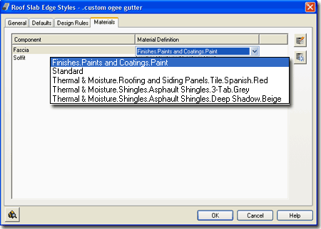
Illustrated to the right I show that Slab Edge Styles will
offer two predefined Components ( Fascia and Soffit ) and that the Material
Definition Name will be set to "Standard" when you create a Style from
scratch. If you have imported any of the Architectural Desktop Slab Styles from the
Object Style Library, you should find that you will be able to use the Material
Definitions that come with those objects.
|
 |
| 8Slab Edit - Trim, Extend, Miter and
Cut |
8-10 SLABS & SLAB TOOLS |
Slab Pop-up Menu
| Mouse |
Select Slab, right-click
and select applicable pop-up menu option |
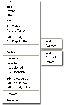
When it comes to Editing or Modifying Slab Objects, you
won't find much in the way of toolbars, palette icons or pull-down menu items. The
full set, as far as I can tell thus far, is only available via the object-specific pop-up
menu illustrated to the right.
If you are a savvy AutoCAD user familiar with all of the
quick and dirty routines that get the job done in seconds, you will probably find the Slab
Editing Tools a bit lacking and basically intolerable. The Trim and Extend tools,
for example, are not only different from the regular Trim and Extend (which, by the way,
Explode your Slabs) but are nowhere near as powerful. I find the SlabExtend routine
so poor that I often Grip Stretch my Slabs through the Edge and then Trim back. You
may notice that you can Trim to a Polyline but you cannot Extend to one (huh?).
Cutting Holes in Slabs is a relatively painless operation
that can be achieve with Rectangles that don't even share the same Z-axis coordinate so
you should find that process quite fun. |
|
| Slab Grip Points Slab Objects have several unique Grip Points that
you can use to Edit with. Though many of these may apply more to Roof Slabs, you may
find some of them quite powerful.
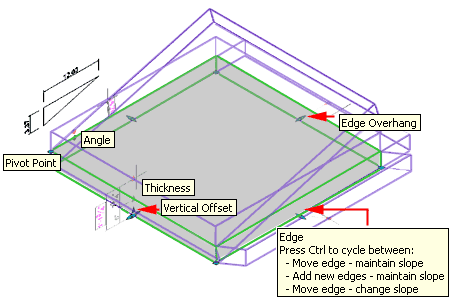
Illustrated to the right I show an Isometric View of a
simple Slab Object where you can see all of the various Grip Points. Angle
and Pivot Point typically apply to Roofs with Slopes but
you can use them to Slope Slabs as well. For very slight slopes, use the Tab key to
cycle through the Rise, Run and Angle settings and then type the number you wish to
set. On Edges, even in Plan View, be careful not to use the Edge Overhang
Grip Control unless you really wish to Stretch the Overhang Value (again, something more
appropriate for Roof Slabs). For Edges, notice that you can use the
Ctrl key to choose between three methods of Stretching the Edge. The method
illustrated, "Add new edges - maintain slope" is a rather powerful way to Add
new Slab surfaces at different Slopes (despite the words "maintain slope"). |
 |
Slab
Trim
| Menu |
N.A. |
 |
 |
| Keyboard |
SlabTrim |
| Mouse |
Select Slab, right-click
and select Trim |
| Links |
Roof Slab Trim - for other
examples |
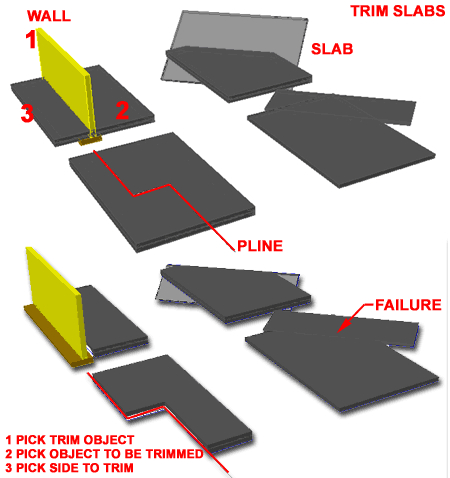
The Slab Trim tool works much like
AutoCAD's Trim command but not with the exact same set of steps. It also works just
like the Roof Slab Trim tool. If you read the command line sequence you will avoid
having trouble with this routine.
To Trim, first select the object that acts
as the cutting edge, then select the Slab
to be Trimmed and then pick a point on the Slab representing the
side to be removed. Unlike AutoCAD's Trim command, you cannot skip any of these
steps.
You can Trim a Slab to another Slab,
Wall or Pline. The Slab Trim tool utilizes
the slope and direction of the cutting object to trim with, so two objects do not need to
pass through each other in 3D space. Since most Slabs are non-sloping ( concrete
slabs and floor slabs ) you may find that you have some difficulty getting two non-sloping
Slabs to Trim each other. I have no tricks for this problem but
have found that a Pline does the job much faster and more reliably.
Slabs then to Trim to each other much better when one has a slope.
When Trimming Slabs to Walls, you may find
that your Slab gets Trimmed back to odd places due to the fact that the Slab Trim tool
will read the out extreme edge or component of a Wall object. This means, for
example, that Trimming back to a Wall with a large footing will result in a Trim to the
Footing and not the stemwall.
If you accidentally use AutoCAD's Trim command instead, the
Slab seems to Explode with disastrous results. It's too bad the regular Trim command
couldn't be use here.
Tip:
Try using Slab Miter instead. Try using Plines instead of Walls or other Slabs. |
 |
Slab
Extend
| Menu |
N.A. |
 |
 |
| Keyboard |
SlabExtend |
| Mouse |
Select Slab, right-click
and select Extend |
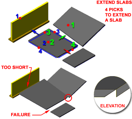
The Slab Extend tool
works much like AutoCAD's Extend command but not exactly with the same set of steps.
If you read the command line sequence you will avoid having trouble with this routine.
See comments for Slab Trim above. Also, if you are having trouble
getting this routine to work, make sure that the objects you are attempting to extend to
actually cross the planar path of the Slab you want to Extend.
You can Extend a Slab to
another Slab or Wall but not a Pline. Flat
level Slabs do not Extend to other flat level Slabs. Extending to Wall objects will
result in an extension to the greatest outer component.
Tip:
Try using Slab Miter instead.
Try Trim instead. Since Trim is easier to use and seems less picky about what you
select, sometimes you can just stretch a slab through and trim it back rather than extend
it. |
 |
Slab
Miter
| Menu |
N.A. |
 |
 |
| Keyboard |
SlabMiter |
| Mouse |
Select Slab, right-click
and select Miter |
The Slab Miter tool works much like
AutoCAD's Fillet or Chamfer command with a radius or distance set to zero. Knowing
this, you may want to use the Slab Miter tool instead of the Slab Trim and
Extend tools since you can effectively get the same results and often faster.
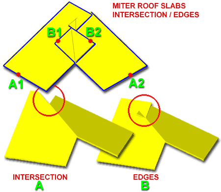
There are two options when you use the Slab Miter
tool: Intersection and Edges. In many cases, both
will produce the exact same results and it all depends on which one you find easier to
use. If you are working with Slabs that have many unique edges and you only
want two different edges to miter, for example, then that's where the Edge option comes in
handy. With the Edge option you can specify the edges that you want mitered.
Illustrated to the right, you can see that selecting B1 and B2
Edges only Miters those two edges and leaves the rest of the Slabs
alone. I have repeated the Roof Slab image to the right because the Miter routine
only works if one or both Slabs are at slopes and this is just what a Roof Slab is so
what's the point; this tool needs further development for use with typical slab situations
and serves as another example of the sloppy nature of the Slab object and its tools. |
 |
Slab
Cut
| Menu |
N.A. |
 |
 |
| Keyboard |
SlabCut |
| Mouse |
Select Slab, right-click
and select Cut |
| Links |
Roof Slab Cut - for more examples |
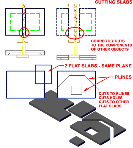
The Slab Cut tool works
much like AutoCAD's Slice command ( from the Solids toolbar ). This is always an
awesome tool to have when working with volumetric forms and thus is my favorite tool in
the Modification set. If all else fails, try this tools.
The Slab Cut tool recognizes the objects
that do the Cutting far better and more logically than the other Modification tools.
As is illustrated to the right, it can actually read the footing or the stemwall of
a common retaining wall correctly, unlike the Slab Trim and Slab
Extend tools. Another fantastic feature is its ability to read other
similar Slab objects for Cutting and can thus be used to Trim Slabs or introduce Vertices.
When used with Plines,
the Slab Cut tool acts as the perfect knife and can even be used to create Holes.
When using Plines with Slabs for Cutting, be sure to remember that the Cutting tool only
cuts and does not remove objects. Thus if you use it to make a Hole, the hole will
still be there for you to manually Erase or Move - see
illustration to the right. |
 |
| 9Slabs Edit - Add and Remove Vertices |
9-10 SLABS & SLAB TOOLS |
Slab Add Vertex
| Menu |
N.A. |
 |
 |
| Keyboard |
SlabAddVertex |
| Mouse |
Select Slab, right-click
and select Add Vertex |
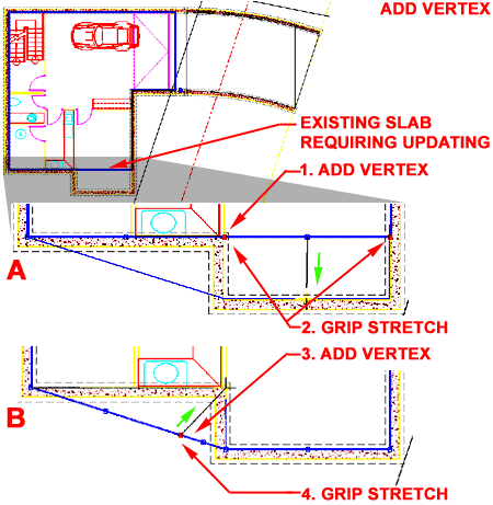
The Add Vertex routine is about as simple
a routine as you can get, so I don't know what I should say about it. You should be
aware that the control points or vertices are on the Slab Baseline and not the
perimeter edge where you might really want it at times. Once you Add a Vertex, you
can use Grips to stretch the vertex in, out, up or down.
If you have used the PEDIT command in AutoCAD for Plines,
you shouldn't have any difficulty with this routine.
At time, such as with the example illustrated to the right,
you can achieve the same results by using a Pline and Extending to it or by Boolean Adding
another Slab drawing in the missing area of floor space. |
 |
Slab Remove Vertex
| Menu |
N.A. |
 |
 |
| Keyboard |
SlabRemoveVertex |
| Mouse |
Select Slab, right-click
and select Remove Vertex |
The Remove Vertex routine is about as
simple a routine as you can get, so I don't know what I should say about it. See
comments for Add Slab Vertex. Use this routine when you mess up on the Add
Vertex routine <hah> |
The
routine will prompt you for the Slab that you want to Modify and then you are prompted to
pick on or near the Vertex you want Removed.
If you have trouble seeing the vertex, you can
use the Endpoint OSNAP to find it. |
| 10Slabs Edit - Holes, Add and
Subtract |
10-10 SLABS & SLAB TOOLS |
Slab
Holes
| Menu |
N.A. |
 |
 |
| Keyboard |
SlabHole |
| Mouse |
Select Slab, right-click,
select Hole and cascade to Add or Remove |
| Links |
Stairs in Model - for information on what
controls the cutting of holes by Stair Objects - see also customization and trick below
for an improved method on this option. |
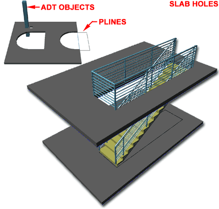
The Slab Hole routine is
really just a Boolean subtraction where the 2D or 3D objects can be used as subtraction
tools. In the illustration to the right, I show one of the more common architectural
needs for cutting a hole in a ; for a stair flight. To cut a stair flight hole draw
a rectangle or other 3D object in the space of the stair. This procedure is actually
far easier if you use Space objects but this servers as an alternative.
The Slab Hole routine
will work on closed polylines and just about all other ADT object types. In some
cases, like with polylines and Mass Elements, the cutting object and the Hole are not
associative but in other cases, where there is already an association, like between Slabs
and Walls, the Hole will move with the cutting object ( in other words, as the Wall moves
so does the Hole it cut ). With more complex objects, like Mass Elements with holes
inside them, the Slab Hole routine will make a query about Subtracting based on the
Inside or Outside of your selected cutting object. Outside
will use a complex object's outer perimeter to cut a hole, while Inside
will look for the smallest opening internal to the cutting object. In simple
layman's terms, think of a Chimney - do you want the chimney hole subtracted or the whole
exterior mass of the chimney.
To Remove Holes, the
Slab Hole routine is as simple as it can get; simply specify that you want to remove and
pick on the edge ( Face ) of a hole. |
 Grip Editing of Slab Holes is also quite impressive. You
can stretch all of the corners of a Slab Hole simultaneously or independently by
activating multiple "hot spots" or working with only one at a time.
Stretching in
plan view is also a very practically way to adjust a Hole, especially if you simply
want to move a hole - simply stretch the whole Hole. |
Slab
Boolean
| Menu |
N.A. |
 |
 |
| Keyboard |
SlabBoolean |
| Mouse |
Select Slab, right-click,
select Boolean and cascade to Add, Subtract or Detach |
| Links |
Barrel Vaults - for an example of a
Boolean Add |
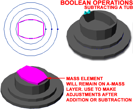
The Boolean Add, Subtract
and Detach options are all based on the same tools found in AutoCAD's Solid
Editing tools and Architectural Desktop's Mass Groups tools.
In Architectural Desktop, you will find that using a Boolean Add or Subtract
achieves two things: it effectively Adds or Subtracts matter to/from the Slab and
associates with the Boolean object so you have a reference object to work with. With
Mass Elements, used as Boolean objects on a Slab for example, the
Mass Element will not be removed, is associated with the Slab, can be used to modify
the proportions of your Addition or Subtraction and is stored on the A-Mass
layer ( in default ADT ).
Detach - will remove the association
between the Boolean object and the Slab and its effects on the Slab; basically this
is like an Undo for a Boolean operation. |
 |
| 11Slabs - Customization and Tricks |
11-10 SLABS & SLAB TOOLS |
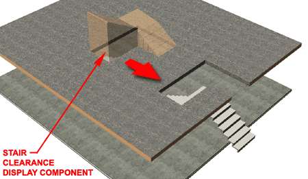
| Stairs as Boolean Subtractions
Stairs have a built-in Display Component called "Clearance"
and you can use this 3D Mass to act as a hole-making entity for Slabs. Though you
can use the SlabHole command to cut a hole, I found that using a SlabBoolean
Subtract works a lot better because the hole created by this routine
follows the Stair Object as you move it or adjust its physical characteristics.
Illustrated to the right I show what the
"Clearance" Display Component looks like when its Visibility is On and how the
Subtracted space follows the Stairs as it was moved to the outer edge of the Slab.
|
 |
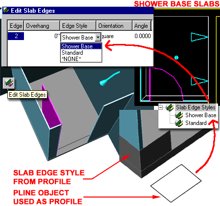
| Shower
Bases
Illustrated to the right is a quick solution I came up one
day after trying to find a shower in ADT's library that suited my needs. There
aren't any for most of my jobs so I decided to use a Slab which seems appropriate.
Though there are some limitations to what you can do with the Slab Edge Styles,
like the inability to fillet joints, creating a Shower Curb is very easy and can be used
for a huge variety of Shower Base dimensions.
Illustrated to the right I show the use of the Edit
Slab Edges tool as a means for taking any simple slab and adding this shower curb
but you can also create a Slab Style with Slab Edges already set to go.
Tip:
Assign the the Profile as a Soffit if you want the edge line of the curb to show up in
Plan View. |
 |


 The Slab
Object is basically little more than a copy of the Roof Slab Object and thus you will find
a lot of similarities. At times you may find the jargon for Roof Slabs a bit
confusing since they are based on Roof Slabs; terms like Soffit and Fascia but if you
think in terms of a flat or low pitched Roof then you should have no problems working with
this Object.
 They can also be set to automatically read Stair objects
and create an appropriately sized hole by using the Space Interference tool. What
Spaces do not have, is the option for Edge Styles but if this is not something you need, I
suggest you try working with Space objects before settling for Slab Objects.
 The Slab
Object is often used by designers as a generic all-purpose 3D Massing Object for
things like table tops, ceilings, streets, sidewalks and so on. This practice may or
may not be a good approach to solving problems in ADT but as long as you are aware of how
this object functions and displays, you should feel comfortable using it as creatively as
you can. For some design problems, however, I find using other Object Styles a bit
superior; such as using Wall Styles for countertops and full cabinetry. The biggest
attribute the Slab Object offers is the option to create custom Slab Edges - discussed
below.
 Vertical
offset - this value field offers the option to raise or lower a Slab in
the Z-axis along its Pivot Point. This is more of an option you would expect to use
for Roof Slabs but can be applied to Slabs that need to slope for drainage or other needs.


 Style - allows you to
change the selected Slab to any other Slab Style currently loaded in your drawing file.
 On the Dimensions tab of the Slab
Properties dialogue box you can override the Style settings by specifying unique
values for the selected Slab.
 trouble by
outlining as many of them as I can here.


 Illustrated
to the left, is another way to access the Display Properties tab; select
the specific object, right click on your mouse
to invoke the object-specific pop-up menu and select Edit Object Display... Just
be aware that when you use this approach, you can actually set an Object Override as
opposed to a Style Override. Object Overrides can be extremely useful because they
allow you to add hatch patterns or change colors of any single object within a Style
Family but they can also be problematic because they lock you out from more centralized,
Style level, controls.
 Illustrated
to the right I show how you can do some minor changes to the Plan Display
Representation of a Slab Style to achieve a more "AutoCAD-like"
level of control over the Color, Linetype, Lineweight
and so on of certain Components. By removing the By Material
checkmarks from the Below and Above Cut Plane Body Display Components, you can use the
ByBlock setting to acquire the freedom to set the Color by Layer or by manual override.


 If
you have read the Roof Slab Above and Below the Cutting Plane discussion in Part 8, you
should comprehend how the Cutting Plane Height relates to Roof Slabs but Slabs or Floor
Slabs, as one might call them, is another matter with its own Cut Plane issues.
Since the default Global Cut Plane Height ( 3'-6" Imperial or 1400mm
Metric) was designed for Walls, Doors, Windows and so forth, it may not be the ideal
height for your Slabs and thus this may be one of the first settings you will need to look
into to get better display results.


 The Design Rules tab of the
Slab Edge Styles dialog box holds all of the settings that create the amazing
Fascia and Soffit results. Since Soffit and Fascia are not the normal terms applied
to Slabs but rather Roofs, you should feel free to be creative about the terms Fascia and
Soffit and how they actually apply to your Slab Edges.


