| 1Elevations - Access |
.1-14 ELEVATIONS |
Elevations Toolbar
How do I get this toolbar?
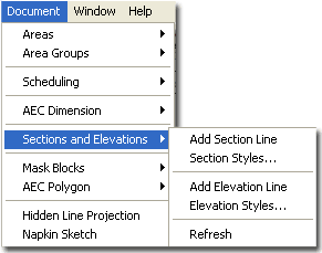
You can also acquire access to these commands from the Alternate Document
pull-down menu. From the Document pull-down menu, pick Sections
and Elevations > and cascade to their respective command options - see image
below, right. |
 |
| Elevations Pull-down Menu and Tool Palette 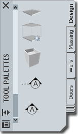 In ADT
Elevations and Sections are broken up into two separate tasks though they are basically
identical objects using nearly all of the same tools. This means that you can
actually use the Elevation Line Object to create Sections and the Section Line Object to
create Elevations. It's a bit silly, isn't it and we should really just think of
this type of work as creating Projections because you can use either object to do Interior
Elevations as well. In fact, you can also use the Documentation Symbols to produce
the same results. In ADT
Elevations and Sections are broken up into two separate tasks though they are basically
identical objects using nearly all of the same tools. This means that you can
actually use the Elevation Line Object to create Sections and the Section Line Object to
create Elevations. It's a bit silly, isn't it and we should really just think of
this type of work as creating Projections because you can use either object to do Interior
Elevations as well. In fact, you can also use the Documentation Symbols to produce
the same results.
When you get ready to use the Elevation or
Section Line Objects, think about what you want as the product of this
"projection" and where you want it. For example, on a single story
residential building you might have all of the information you want in one file but do you
want the Elevations or Sections in the same file? On a larger commercial project, as
another example, you will have all of the floors in separate files so in order to generate
an Elevation or Section, you will need to create a composite file.
For both scenarios described above, I typically Xref
everything I want for my Elevations and Sections into a Composite File where I add the
Elevation and Section Line Objects and Generate the work need. Once this work has
been Generated, I use Layout Tabs to set up the Sheets. |
 Most designers are familiar with the concept of
a 2D Elevation or Section so that part of this process is relatively self-explanatory but
ADT offers a new twist on this concept: 3D Elevations and Sections. Most designers are familiar with the concept of
a 2D Elevation or Section so that part of this process is relatively self-explanatory but
ADT offers a new twist on this concept: 3D Elevations and Sections.
For Elevations, I prefer to use the 2D option
because I typically break the live-link to the model at some point in order to finish off
the work with linework that I just don't bother to add in Models. The 3D Elevation
Object is basically a copy of the Model with Subdivision Controls for Color/Lineweights.
Note:
Since Elevations and Sections are basically the same thing in ADT, you might want to read
up on Live Sections as another option for Elevations. |
| Elevations - Overview Discussion 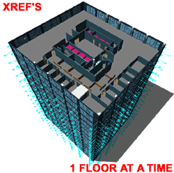 Elevations, what's the big deal? Elevations, what's the big deal?
Just pick on the View Front button and Viola, Front
Elevation, right?
Yes and No.
During the Design phase of a project, cranking out rapid
elevations with the View buttons is a reasonable solution but once a set begins to look
more like Development and Construction Documentation, you may want those Elevations to
look a bit different than what you get automatically with the View buttons and the
Elevation Representation Sets. You may want lines that are beyond to look lighter,
for example. In addition to the lineweight issues, you may want to begin adding
details to your elevations that you will never model. And you may also be working
with sub-contractors who cannot deal with 3D objects, especially ARXobjects.
So, what seemed relatively easy suddenly gets more
complicated. What you will need to think about is the long term projected goal and
the intermediary steps you can take to get there. We've just discussed one of those
steps: using the View buttons.
The next step might just be to get Elevations that have
better lineweights followed by another step where the Elevations are 2-Dimensional.
The final step might likely be that your Elevations are
2-Dimensional non-associated Lines, Plines, Hatches, Text and so forth - the way
Elevations have been done in AutoCAD for about 20 years now. You may be one of the
few fortunate people who won't end up at this step but will actually be able to keep your
Elevations linked to your model all the way through construction and even into archiving.
|
When
you get ready to use the Generate Elevation dialog box, you will have 2 choices in how you
want the take the next step. The first choice allows you to create an Elevation that is still
3-Dimensional but with the power to control lineweights relative to depth of
field. The second choice allows you to create a 2-Dimensional Elevation with
lineweight control.
As you can see then, you might want to start
with the 3D Elevation and then later move on to a 2D Elevation that eventually may end up
as a non-associated 2D line Construction Document.
Personally, I like going straight to 2D if I
am going to go through the trouble of generating an Elevation to begin with.
Single Building Model vs. Composite
Building Model
Assembling a body of work in order to create
an Elevation is another subject that can be discussed and debated greatly. There
does seem to be a majority vote on the Xref approach rather than
attempting to build one model in one file that solves all documentation needs. ADT's
Project
Browser emphasizes this approach and finally advocates the concept that
buildings are made of pieces brought together rather than a whole broken apart.
Though I believe one individual could probably make the one-model-does-all scenario work
rather well, I would never advocate such a solution. Even on a small project, like a
one-room remodel, I rely on Xref's.
By separating as much as possible into unique
files, you not only provide others with the opportunity to work on a project
simultaneously, but you provide yourself with another form of Layering. Though I
completely comprehend the idea that if more is in one file, you can more easily edit it, I
have found that I am actually more likely to lose information in the clutter.
Instead, I simply run many files open at the same time and refer back and forth when
necessary or rely on Edit-in-Place functionality.
By the time you are ready to Generate
Elevations, you should also have one or more Composite files ready since most of your
working drawings probably have everything else Xref'd in. I usually create a Model
file where I Xref everything in and add other things that I want for Perspectives,
Renderings, Sections and/or Elevations; like 3D topographic contour work, street and curb
information, adjacent and background information and decorative elements such as cars,
trees and people. |
| 2Adding Elevation Lines |
.2-14 ELEVATIONS |
| Adding Elevation Line Objects
Adding an Elevation Line Object
is a far easier task than figuring out how to put a project together to take advantage of
this tool.
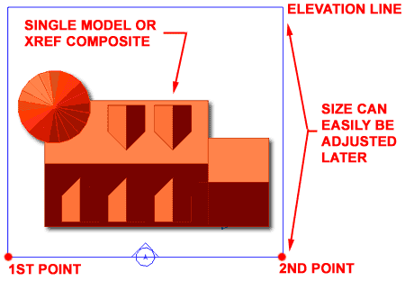
Illustrated to the right, I show a simple project viewed
from the top with the two points that were used to create an Elevation Line,
highlighted in red. From two points selected along the side that you wish to project
an elevation from, you get a bounding box that will eventually surround or envelope your
model. The size and depth of your elevation line ( square ) is not something you
should be too concerned about at this point since you can easily adjust it after creation,
with Grip Editing. Eventually it should surround everything you want in your
Elevation or it will cut information out.
The Elevation Bubble is more of a tracking tool for you
than for proper annotation; though you can certainly use it as a proper annotation
symbol. There are better Elevation Marks in ADT that you can access from the Annotation
tab of the Tool Palette or go to the Elevation Marks folder
under the Documentation folder in the Design Center (type "_AecDcSetImpElevationMarks"
or "_AecDcSetMetElevationMarks" for Metric).
For multiple Elevations, you can draw an Elevation Line for
each side or Copy one Elevation Line object, Rotate
it and position it as you like. If you happen to lose the elevation symbol,
don't worry about it because that symbol does not affect the creation of the elevation;
i.e., the frame is the actual tool - see the Display Props
discussion for how to Color Code the "Defining Line". |
 |
| 3Modifying Elevation Lines |
3-14 ELEVATIONS |
Elevation
Line Properties - Dimensions tab
| Menu |
N.A. |
 |
 |
| Keyboard |
BldgElevationLineProps |
| Mouse |
Double Pick on Frame
- Properties Palette |
| Links |
|
On the Properties Palette for the Elevation
Line Object, illustrated to the right, you will find an assortment of options
that control the proportions and segments.
 Dimensions Dimensions
Use Model Extents for Height - this drop-down list has a Yes or No
option and applies to the overall size, in 3D Space, of the object selected when using
this Elevation Line Object as a tool. In most cases you will probably want to Use
Model Extents ( Yes ), but for Interior Elevations you would not want to this option on.
Subdivisions - when you pick on this
cell, you will activate the Subdivisions dialog box where you can Add, Edit or Remove
Subdivisions Lines. Subdivisions are measured from the Elevation Defining Line in
and represent sectional divisions where you want the lineweight/color to vary. In
other words, adding a Subdivision half way along your Elevation Boundary box will allow
you to change the colors, linetypes and lineweight of all the lines/objects that lie
beyond the subdivision line.
Lower Extension - (Use Model
Extents for Height must be set to No) - an amount of space
extended below the default ground plane for an Elevation Line. The default will
capture information that lies 12 inches ( 308 mm ) below the World Coordinate System or
Ground Plane. See Part 15 -
Sections for an example.
Component Dimensions
A Side 1 - use this value field to specify the length of the boundary from the
1st point used to create the Elevation Line Object. Grips can be used to modify this
value as well.
B Side 2 - similar to A Side 1. |
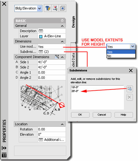 C Angle 1 - use this value field to specify the
taper angle of the boundary from the 1st point used to create the Elevation Line Object.
Grips can be used to modify this value as well. Negative Angles are allowed.
This can be useful when trying to clip objects in or out of a Elevation that are
not parallel or perpendicular to the Elevation Line Object.
D Angle 2 - similar to C
Angle 1.
Location
Rotation - based on the global angle similar to all objects.
Elevation - if Use
Model Extents for Height is set to No, this can be used
to move the Elevation Line Object up or down relative to the Model and can thus be used to
control the bottom of the elevation projection; e.g., for a portion of a multi-story
building, like a single floor of a high-rise. |
| Modifying
an Elevation Line with Grips When you Select
an Elevation Line Object, you should see several Grip
points activate that you can use to edit with. These Grip points correspond to the values
that you set on the Properties Palette for an Elevation Line Object.
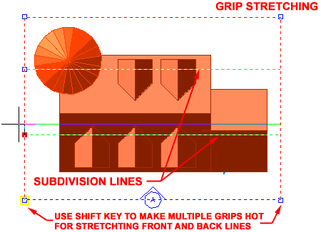
Grip Stretching Subdivision Lines is as easy as it gets
because you only have one Grip to work with. Grip Stretching any of the four corners
of an Elevation Line may pose more of a problem. Since the Elevation Line Object
supports irregular shaped tetragons, you can stretch any corner uniquely. If you
don't want an irregular shape, simply use the Shift key while making your
Grip spots HOT. This will allow you to work with two Grips at the same time and
thus you can Grip Stretch one side evenly to exclude or include more of your project. |
 |
| 4Elevation Line - Display
Props |
4-14 ELEVATIONS |
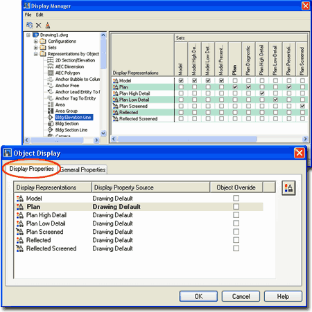
| Object Display... -
Elevation Line 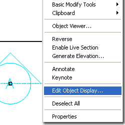 The Elevation Line object in ADT does not have a Style but you can
use Edit Object Display... to access its display controls. On the Object
Specific pop-up menu, illustrated left, select Edit Object Display... On
the Object Display dialog box choose a Display Representation, like Plan
and double pick on it or pick the Edit Display Props... button. The Elevation Line object in ADT does not have a Style but you can
use Edit Object Display... to access its display controls. On the Object
Specific pop-up menu, illustrated left, select Edit Object Display... On
the Object Display dialog box choose a Display Representation, like Plan
and double pick on it or pick the Edit Display Props... button.
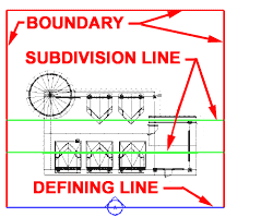
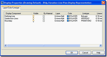
The only Display Props you can edit for an Elevation Line
object are on the Layer / Color / Linetype tab. On this tab you
should find three Components: Defining Line, Subdivision
Lines and Boundary.
Tip:
If you color code these components, they are a lot easier to read when looking at them on
your screen - see discussion below for how. |
 |
| Display
Properties - Elevation Line - Component Layers From the Display Props tab, in Plan
view or other Representation Sets, you can use the Edit
Display Props... button to access the component's Layer/ Color/ Linetype
tab.
 Notice on the Elevation Line's Display Properties
dialog box, right, that you have three components that you can work with: Defining
Line, Subdivision Lines and Boundary. Notice on the Elevation Line's Display Properties
dialog box, right, that you have three components that you can work with: Defining
Line, Subdivision Lines and Boundary.
The Defining Line represents the side,
direction and Width of the Elevation you intend to create.
The Subdivision Lines are internal Lines
that you can set under the Dimensions category on the Properties Palette. These
Lines can be used to control Color and Lineweight changes within the Elevation you
generate with this Elevation Line. Typically, you will use this technique to imitate
the way we have traditionally shown lines as lighter when farther back.
The Boundary represents the area that
surrounds your building or project. |
 |
| 5Creating Elevations |
5-14 ELEVATIONS |
Generate Section/Elevation dialog
box
| Menu |
N.A. |
 |
 |
| Keyboard |
BldgElevationLineGenerate |
| Mouse |
Select
Elevation Line Object, right-click and Select Generate
Elevation... |
| Links |
|
When you are ready to actually create an Elevation, you
will use the Generate Section/Elevation dialog box, illustrated to the
right, to define the type of elevation you want; what you want in it, what it should be
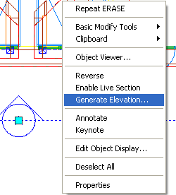
displayed like and where you want it placed. To Generate an Elevation, you can
type "BldgElevationLineGenerate" or simply Select your
Elevation Line Object, right-click to invoke the object specific pop-up menu
illustrated to the left and select Generate Elevation...
 Both
types are linked to the original drawing and thus can be updated to reflect your design
changes at any given time. This will be discussed below. Both
types are linked to the original drawing and thus can be updated to reflect your design
changes at any given time. This will be discussed below.
Result Type
3D Section/Elevation Object - a copy of your drawing presented as an
elevation object where subdivisions and other Elevation Line settings are displayed.
2D Section/Elevation Object with Hidden Line
Removal - a projection on to a plane of your drawing where subdivisions and other
Elevation Line settings are displayed. You can think of this as being much like a
block or Xref associated with the Elevation Line and your original drawing. If
exploded two times, you will get 2D line work.
Style
to Generate - the default "Standard" is all that
you will find anywhere in ADT until you create your own. A custom Style will allow
you to refine line colors and weights for objects within your 2D Elevation.
Style for User Linework Edits if
Unable to Reapply - this option is only available when Updating a Section or
Elevation that has had Linework Editing. You can use it to save the Editing to a new
Style Name so the edits can be reapplied upon future update/refreshes.
Selection Set
Select Additional Objects - this button is active only after an Elevation
Line has been associated with objects. It can be used to select more new objects to
be associated. This may be useful when you want to create a set of elevations from
the same Elevation Line where each one contains different or more information.
Select Objects ( Reselect Objects ) - this
button changes once an Elevation Line has been associated with objects. This button
allows you to reset what you want associated with your Elevation Line and thus, using the
Shift key, you can also deselect objects. |
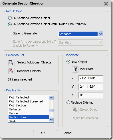
Display Set - this should be
an obvious option for you at this stage of a project but if there's still some
uncertainty, you should read up on Display Representation
Sets. Basically this is just how you want objects to look in "Elevation
View". One example is how Doors have the swing indicated by centerlines.
Placement
New Object - this radio button tells this dialog box that you want to
create a new elevation object. Leaving this radio button checked while trying to
adjust an existing elevation will result in duplicate elevation objects right on top of
each other, so be careful about this option. A good way to avoid making a mistake is
to select the elevation object itself, right-click, and then select the Refresh option on
the object-specific pop-up menu.
Pick - this button with X, Y
and Z corresponding values simply allows you to locate the lower left insertion point of
your elevation object. Since you can move it at any time after creation, it isn't a
big deal where you put it.
Replace Existing - this radio
button should be used when you are in this dialog box without having used the Update
route. In other words, if you simply used the Generate Section command or button to
work on an existing elevation object. By checking Replace Existing, you will be
asked to Select Object. This object has to be the existing elevation object that you
intend to modify or update. After doing this selection, you can then proceed to
Reselect Objects, deselect objects or select Additional Objects. Once again, it's a
lot easier to simply pick the elevation object, right-click, and use the Refresh option. |
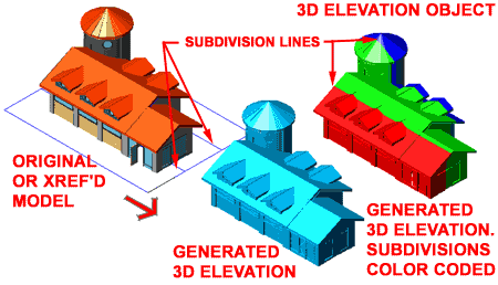
| 3D Elevation Object Example
Illustrated to the right I show the default 3D
Elevation object and how the same 3D Elevation object can be adjusted to reflect
the Color changes ( lineweights ) for the Subdivision lines on the
Elevation Line object.
To change the Colors, as illustrated,
select the 3D Elevation object, right-click and use Edit Object Display... as
outlined below. |
 |
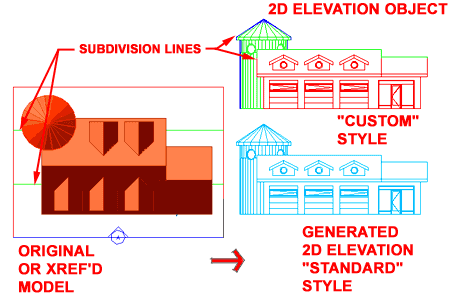
| 2D Elevation Object Example
Illustrated to the right, I show the default 2D
Elevation object and how the same 2D Elevation object can be adjusted to reflect
the Color changes ( lineweights ) for the Subdivision line on the
Elevation Line object.
To change the Colors, as illustrated,
select the 2D Elevation object, right-click and use Edit Object
Display... as outlined below. |
 |
| Comments on
Display Representation Sets for Elevations and Sections If you don't choose the right Display Representation Set
when you generate an Elevation or section, the objects generated in the
automatic Elevation or section may not come out right. For example, you might only
see a single horizontal line in an elevation view if you chose the PLAN Display
Representation Set.
These Display Representation Sets tell ADT how to represent
your Doors, Windows and other objects in an elevation or section as opposed to a plan
view. A door, for example, will have a frame with a swing triangle in an elevation
but not in a plan. If you recall, Display Representation Sets are actually groups of
all the Display Representations; one for each Object Family. |
When
you select the Section_Elev Display Representation Set, you will be prompted to provide
how far you want your new elevation object away from the actual model. Think of this
as the Move command in AutoCAD.
When you have placed the new elevation object,
it should look something like the illustration above. This new copy is actually linked to
the original via the Elevation line. |
| 6Modifying Elevations |
6-14 ELEVATIONS |
Regenerate Elevation
| Menu |
Documentation>
Elevations> Update Elevation... |
 |
 |
| Keyboard |
BldgSectionUpdate |
| Links |
Generate
Section/Elevation dialog box - for information on all of the other features not
discussed here for Regenerating. |
 Once 2D or 3D Elevations have been created, you
can Regenerate them to update for changes made in the model, change the
original selection set or make other changes offered on the Generate
Section/Elevation dialog - illustrated right. For 3D Elevations, the option
to use Styles is not available and for 2D Elevations, the option to save Edits to another
Style is only available if "in-place" editing has been done and if another Style
exists. Once 2D or 3D Elevations have been created, you
can Regenerate them to update for changes made in the model, change the
original selection set or make other changes offered on the Generate
Section/Elevation dialog - illustrated right. For 3D Elevations, the option
to use Styles is not available and for 2D Elevations, the option to save Edits to another
Style is only available if "in-place" editing has been done and if another Style
exists.
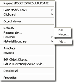
Though this command can be activated by typing or creating
a custom tool, the easiest way to Regenerate is to Select an Elevation
Object ( not the Elevation Line Object ), right-click on
the mouse and select Regenerate... off of the object-specific pop-up menu
- illustrated left. You can only Regenerate one Elevation Object at a time but you
can Refresh as many as you wish to Select.
When Regenerating, the Generate Section/Elevation
dialog is used and just about all of the options, conditions and results are the
same. You can even create a New Elevation by Regenerating an existing one ( just use
the New Object and Pick Point buttons ). This means that you really only need to use
this tool when working with 3D Elevations ( which I never do ) and when you need to Save
2D Linework Edits to a New Style and/or change the Selection Set. For most other
forms of updating, use the Refresh option discussed below.
Note:
Though you can easily change the 2D Section/Elevation Style by changing the Style to
Generate option when Regenerating, you can also just use the Properties Palette
to change the Style. |
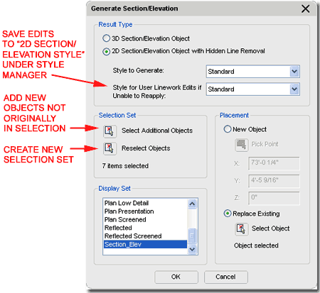
Style for User Linework Edits if
Unable to Reapply - a drop-down list that offers any 2D Section/Elevation Styles
to save the Edited linework to. In plain English, this option is for when you
Regenerate an Elevation knowing fully that some or all of the Edited Linework from a
previous editing session will not translate correctly ( match up or fit ), but you would
like to save it as a separate block to compare with. This new block can be set to
display differently, like with all red lines, so you can more clearly see the edited
linework that is no longer embedded. Read the Summation, below,
for more information. |
Refresh Elevations
| Menu |
N.A. |
| Alt. Menu |
Document>
Sections and Elevations> Refresh |
| |
N.A. |
| Keyboard |
2dSectionResultRefresh |
| Mouse |
Select Elevation
Object(s), right-click, Select Refresh |
| Links |
|
This tool allows you to Regenerate one or more
Elevation Objects without having to use the Generate Elevation/Section dialog box
and thus acts more like a Refresh tool. |
By selecting
one or more Elevation objects and right-clicking, you
can use the Refresh option on the object specific pop-up menu
to achieve the same results |
Elevation - Properties Palette
| Menu |
N.A. |
 |
 |
| Keyboard |
BldgSectionProps |
| Mouse |
Double Pick on
Elevation Object |
| Links |
|
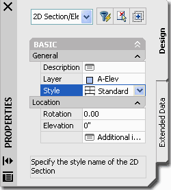
Since Elevation Objects are fairly simple with respect to
options, the Properties Palette will reflect this fact. For 2D Elevations and
Sections, you can change the Style and for 3D Elevations and Sections,
you can only change position based items in the Location Field since 3D Elevations and
Sections have no Styles.
You may want to use this button to provide a Description,
Attach notes and Property Sources. |
|
| Elevation - Edit Linework
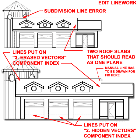
 For 2D Elevations you can use an editing process
somewhat similar to "Edit In Place" for Xref's that allows for some fairly
limited linework modifications. These "Edits" might be for things like
changing the Color or Linetype of certain lines or Removing lines that you don't want to
show in the Elevation Object. To activate, Select the Elevation
Object, right-click, Select Linework
and cascade over to the Edit option on the object-specific pop-up menu (
see illustration to the left ). For 2D Elevations you can use an editing process
somewhat similar to "Edit In Place" for Xref's that allows for some fairly
limited linework modifications. These "Edits" might be for things like
changing the Color or Linetype of certain lines or Removing lines that you don't want to
show in the Elevation Object. To activate, Select the Elevation
Object, right-click, Select Linework
and cascade over to the Edit option on the object-specific pop-up menu (
see illustration to the left ).
Once you have activated the Linework Edit session, the
Elevation Object will behave much like regular linework so it is rather easy to work on it
as if the lines are free for normal editing and it is also rather easy to forget to "Save
Changes" (see below).
You cannot edit the lines as you would for a normal AutoCAD
file because these lines actually reside within the Elevation Object and its Style.
To make linework changes that are saved back into the Elevation Object Style, you must use the "Modify Component..." option
from the object-specific pop-up menu.
When you Edit Linework, the lines must be
assigned to Components within the Elevation Object's Style for proper Display Property
results. This way, when Saved, the Edited or reassigned linework will be
recalculated according to the Component assignment and display representation. |
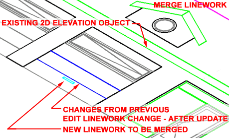
When you Merge Linework,
which are new lines that you want to add to an existing Elevation Object, you must assign
them to Components within the Elevation Object's Style just as for Edited Linework.
To Delete Merged Linework,
use the Edit option, Delete the objects and Save Changes.
To Delete Object Linework generated by the
model, use the Edit option, Modify Component... option and change the linework to the
Erased Vectors Linework Component.
Note:
Edited Linework will "drop out" of the Elevation Object after a Refresh or
Regenerate action if the objects changed in the source model after the editing was saved.
The resultant linework will reside as new objects on top of the Elevation Objects
that can be Erased. |
| Elevation -
Modify Component
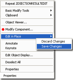 Once you have activated the Edit in Place function for a 2D
Elevation, you can Select any part of that Elevation Object, right-click to see new
options on the object-specific pop-up menu: Modify Component and Edit
in Place with Discard Changes and Save Changes. Once you have activated the Edit in Place function for a 2D
Elevation, you can Select any part of that Elevation Object, right-click to see new
options on the object-specific pop-up menu: Modify Component and Edit
in Place with Discard Changes and Save Changes.
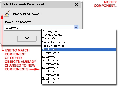
The Modify Component... option activates
another dialog box, illustrated right, that provides an unusual way to edit linework that
is embedded within the Elevation Object. Because the Elevation Object is
"live-linked" to the source model, edited linework must be saved in a unique way
in order for that edited work to be regenerated in the future. Unfortunately this
aspect of editing linework for Elevation Objects is thus tedious and time-consuming so you
may want to solve editing needs another way ( see comments below under Summation).
The Match existing linework option on the
Select Linework Component dialog box allows you to use a tool like Property Painter to
capture the Component of other linework in the current Elevation Object and apply it to
object(s) being edited.
The Linework Component drop-down list provides
access to the Component Names of the current Elevation Object's Style
( the list illustrated to the right is the default list but you can add your own
component names ). When you select a Component Name, the linework being edited
will be associated with the Display Properties for that Component as set within the
current 2D Elevation / Section Object Style. Some of the default Component Names
have some very practical Display Properties that you can easily take advantage of; such as
Hidden Vectors ( dashed lines ) and Erased Vectors ( deleted lines ). |
When you are done editing your Elevation
Object, you must end the "Edit in Place" session much as you would for Xref's
and this is done by selecting the Save Changes option via the object
specific pop-up menu. Any changes that have been made to the current Elevation
Object via the Select Linework Component dialog box will be saved using the current
Elevation Object Style. |
Elevation - Merge Linework
| Menu |
N.A. |
 |
 |
| Keyboard |
2dSectionResultMerge |
| Links |
|
New Linework can be Merged into a 2D Elevation Object by
using the Merge option from the object-specific pop-up menu; acquired by selecting an
Elevation Object and right-clicking.
When you Select one or more objects to Merge, the Select
Linework Component dialog box will appear requesting that you assign the Merged
Linework to a Component Name ( as discussed above ). |
 |
| Modify
2D Sections/Elevations Summation: Working
with 2D Elevations is fairly easy and rather efficient up until the point where you need
to make specific refinements that have to be done right on the Elevation Object rather
than in the Model from which it has been derived. The use of Edit in Place and Merge
for Linework can be useful in a pinch where you do not wish to Explode the Elevation
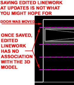
Object and lose the live-link. Be aware that Edited Linework cannot be saved in such
a way that it is truly tied to the objects that the lines have been derived from. In
other words, if you change the lines for a garage door to a dashed Component ( like Index
9 ), for example, those lines will not move with the garage door if it has been moved in
the Model file. Instead, by default, the linework is placed on top of the
Regenerated 2D Elevation as a separate 2D Elevation Object. To assist in managing
this, you will find that option to change such Edits ( that cannot be reapplied ) to
another 2D Section/Elevation Style. If you create another 2D Section/Elevation Style
for this type of linework and use only Red Line, for example, then you can use this Style
to see when linework has been disassociated from the Elevation Object.
Generally, I find that Editing and Merging Linework is not
worth the trouble it takes to worry about components and associations so we, at ARCHdigm,
have developed a technique where we copy a live-linked Elevation Object to the side and
Explode it two times. We edit the exploded Elevation as we would in the old days of
regular AutoCAD drafting but use the original live-linked Elevation Object to update any
changes made to the Model file. When changes have occurred, we copy the live-linked
Elevation Object once again to another location, Explode it two times and copy out only
those lines that need to be added to the first Exploded Elevation. In other words,
we have a simple 2D line drawing for an elevation that was originally created from the
Model but now gets updates from another copied and exploded elevation. The trick to
using this technique is to pick the right time to start developing the Exploded elevation. |
|
| 73D Elevation - Display
Props |
7-14 ELEVATIONS |
Object Display... - 3D Elevation
| Menu |
N.A. |
| |
|
| Keyboard |
ObjectDisplay |
| Mouse |
Select Elevation
Object, right-click, select Edit Object Display... |
| Links |
Object Style Display Properties
- for more information on working with the Display Manager |
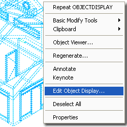 The 3D Elevation object in ADT does not have a Style but you can use
the Edit Object Display... menu option to access and manage unique
display controls. On the Object Specific pop-up menu, illustrated left,
select Edit Object Display... On the Object Display dialog, illustrated to the
right, choose a Display Representation to modify or Override. Use the Override if
you don't want your modifications to apply to all 3D Elevation Objects in the current
drawing. The 3D Elevation object in ADT does not have a Style but you can use
the Edit Object Display... menu option to access and manage unique
display controls. On the Object Specific pop-up menu, illustrated left,
select Edit Object Display... On the Object Display dialog, illustrated to the
right, choose a Display Representation to modify or Override. Use the Override if
you don't want your modifications to apply to all 3D Elevation Objects in the current
drawing.
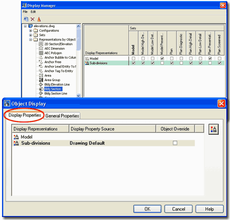
By default, there is really only one Display Representation
that you can Modify or Override for 3D Elevation Objects and that is the Sub-divisions
Display Representation. This Display Representation controls how you want the
"Defining Line" and Subdivisions to appear in your 3D Elevation Object.
Illustrated below I show how this can be used to color code the subdivisions.
Note:
Be aware that the Sub-divisions Display Representation for 3D Elevations actually comes
from the Bldg. Section Object as illustrated above right on the Display Manager Window.
This means that any changes you make to the Sub-divisions ( without overrides ) can
affect Section Objects as well. |
 |
| Display
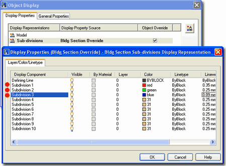
Properties - 3D Elevation - Component Layers On the Layer /Color /Linetype tab of the Display
Properties dialog box, illustrated to the right, you will find the power to
control the Color ( and consequently Lineweight for Color Dependant Plot Tables or .CTB
files ), Layers, Linetypes, Lineweights, Lt Scale, Plot Style ( for .STB Plot files ) and
Visibility. The By Material option is not available for this Display Representation.
Illustrated to the right I show that I have Attached an
Override for the 3D Section/Elevation Entity Property Source since I want these changes to
be reflected on this 3D Elevation object only and not all 3D Elevation and Section objects
in my drawing.
Defining Line - is the default color of
your 2D Elevation but is primarily designed for the outline of a Sectional Cut right at
the defining point of the cut. If you have and use the Subdivisions, this Component
Color will not matter.
Subdivision 1 - 10 - a default set of
subdivisions that are automatically associated with physical
subdivision lines on your Elevation or Section Line object. |
 |
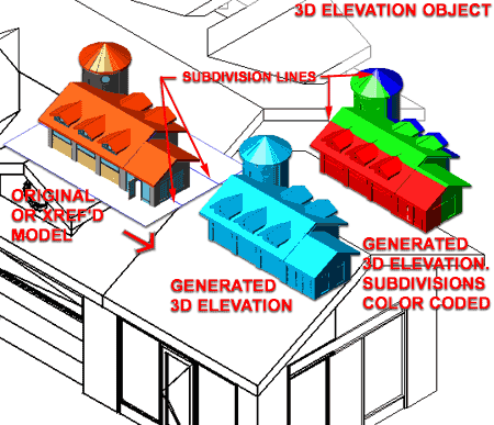
| Display Properties - 3D Elevation - Component Layers - Example Illustrated to the right I show the default 3D Elevation
Object and how the same 3D Elevation object can be adjusted to reflect the Color
changes for the Subdivision lines on the Elevation Line object.
To change the Colors, as illustrated,
select the 3D Elevation object, right-click and use Edit Object Display... as
outlined below.
Notice that for a background, I show what the multicolored
3D Elevation object might look like when plotted in black and white. Though I don't
find much use for 3D Elevations, I have use them to achieve similar types of output.
This technique is actually far more practical and useful on 3D Sections. |
 |
| 82D Elevation Styles |
8-14 ELEVATIONS |
| Style Manager - 2D Section/Elevation
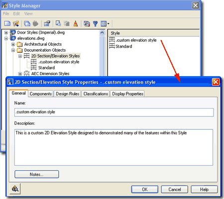
For 2D Elevation objects, you can use the Style
Manager to load, modify, delete and create new 2D Elevation Styles.
Illustrated to the right, I show the process of creating a New
2D Elevation Style that I have Named "Custom Elevation Style".
By double-clicking on this new style, you will invoke the 2D
Section/Elevation Styles dialog box - as illustrated.
The General tab provides access to the Name
and Description fields for a Style; plus access to the attachment of
Notes and Property Sets. |
 |
| 2D
Section/Elevation Styles - Components tab
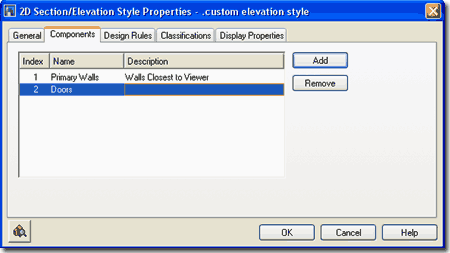
On the Components tab of the 2D
Section/Elevation Style Properties dialog box you can use the Add
button to create custom Component names for use on the Design
Rules tab and on the Layer/Color/Linetype tab of the Display
Properties dialog box.
The basic concept behind this option is to allow you to
define Layer/ Color/ Linetype Component Names that you can use to assign
custom Layers, Colors and/or Linetypes for objects within your elevation. One
example you could think of is a Component for the Swing lines on Doors and some Windows;
often illustrated with a Centerline or Dashed linetype.
Illustrated to the right, I show that I have Added two
unique Components named for what I intend to used them for: Walls and Doors. Follow
the discussion below and you can see how I use these Components to change the line colors
and weights of objects within an elevation object. |
 |
| 2D
Section/Elevation Styles - Design Rules tab
On the Design Rules tab of the 2D
Section/Elevation Styles dialog box you can use the Add button
to create custom rules for what objects within your Model will be assigned unique
characteristics in the 2D Elevation.
The basic concept behind this option is to create a "filter"
that finds objects within your Elevation Line that match your
specifications for Color and Context. Using this
"filter", for example, you can have the Design Rules look for objects that
have the Color 50 and lie in the closest front portion of your Subdivided Elevation Line
to one of your custom Component Names.
Illustrated to the right, I show that I have Added
two unique Design Rules. Rule 1 finds objects in
my example Model whose Layer is set to a Color of 50
and lie within my first Subdivision; it then assigns them to the Component
Name "Walls" that I created on the Components tab.
Rule 2 finds objects in my example Model
whose Layer is set to a Color of 150
and lie within Any Visible portion of my Model; it then assigns them to
the Component Name "Doors" that I created on
the Components tab.
Note:
You don't actually need to create unique Component Names for the Design Rules to work
correctly. You can simply assign objects to a Subdivision that hasn't already been
used. The nice thing about using Named Components is that you can easily track them.
Rule - an index number
automatically generated to assist in tracking.
Color - use the Select Color
dialog box to set the color of the objects you are filter for ( not
against ) If you want to change your Walls and you know they are set to Color 50, then you
set Color to 50. |
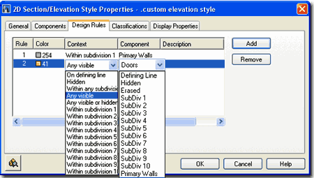
Context - use the drop-down
list to help filter for objects you set by Color. You can use Any visible or Any
visible or hidden to work with your Color selection to find all instances of objects with
that Color. You can also refine your filter by specifying that you only want objects
within a particular subdivision ( as illustrated ). This is how you can make Walls
closer in an Elevation or Section darker than those beyond - even if they are in the same
Subdivision.
Component - use the drop-down
list to specify what to do with the objects that have been filtered for by the Color and
Context options. Component Display, if you realize by know, is
controlled on the Layer / Color / Linetype tab of the Display Properties
dialog box for a particular object or object Style. Using the pre-defined
"SubDiv #" choices is okay as long as you pick numbers out of your range for the
physical subdivisions that you may have on your Elevation or Section Line object. You can also use unique Components, as illustrated with "Walls"
and "Doors", by first creating them on
the Components tab of this dialog
box - see below for how to change their colors. |
| 2D
Section/Elevation Styles - Display Props tab The Display Properties tab on the 2D
Section/Elevation Styles dialog box provides access to the display
characteristics of the components of your 2D Elevation objects; such as what Subdivision
components are turned on or off, linetypes, layers and colors.
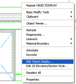 Illustrated to the left, is another way to access the Display
Props tab; select the specific object, right
click on your mouse to invoke the object-specific pop-up menu and select Edit
Object Display... See discussion directly below. Illustrated to the left, is another way to access the Display
Props tab; select the specific object, right
click on your mouse to invoke the object-specific pop-up menu and select Edit
Object Display... See discussion directly below.
|
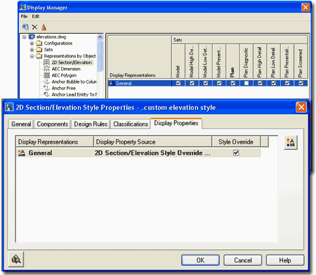 |
| Display Properties - 2D Section/Elevation Styles - Component Layers On the Layer /Color /Linetype tab of the Display
Properties dialog box, illustrated to the right, you will find the power to
control the Color ( and consequently Lineweight for Color Dependant Plot Tables or .CTB
files ).
Illustrated to the right, I show that there is only one
Display Representation option "General" on the Display Properties tab of the 2D
Section/Elevation Styles dialog box. I also show that I have Attached
an Override for the 2D Section/Elevation Style Property Source since this
is a custom Elevation Style that has properties I don't want placed upon other Elevations
or Sections.
Defining Line - is the default color of
your 2D Elevation but is primarily designed for the outline of a Sectional Cut right at
the defining point of the cut. If you have and use the Subdivisions, this Component
Color will not matter.
Outer Shrinkwrap - 2D Sections - see PART 15 -
SECTIONS AND LIVE SECTIONS
Inner Shrinkwrap - 2D Sections - see PART 15 -
SECTIONS AND LIVE SECTIONS
Shrinkwrap Hatch - 2D Sections - see PART 15 -
SECTIONS AND LIVE SECTIONS
Surface Hatch Linework - This Display
Component applies to Hatch Patterns across the surfaces of Walls, Doors, Windows or any
other object that has Material assignments as part of its Style. A Brick Wall, for
example, will display as an Elevation Object with Bricks if this component is turned on
here, a Brick Material has been assigned as a Style Property and the Display Property of
that Brick Material has its Surface Hatch Component turned on. This is very
convoluted and fortunately most of the Wall Styles included with ADT have the proper
settings.
Section Hatch Linework - 2D Sections
Hidden - turned off by default. You
can use this Component when you use the Edit Linework tool to assign lines within your 2D
Elevation or Section a Hidden line appearance. Just make sure it's turned on here.
Erased - turned off by default. As
with the Hidden Component, you can use this Component when you use the Edit Linework tool
to assign lines within your 2D Elevation or Section an Erased appearance. To achieve
this effect, leave the Component turned off.
Unknown Component - I am not sure about
this one but I believe it's like a wildcard Component that you can use creatively -
especially with Edit Linework, but it may be used automatically during such work, I don't
actually know - hey, it's unknown. |
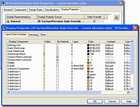
Subdivision 1 - 10 - a
default set of subdivisions that are automatically associated with physical
subdivision lines on your Elevation or Section Line object.
Unique Component Names - these
come automatically when you create a custom Component on the Components
tab of the 2D Section/Elevation Styles dialog box. |
| Unique Component Layers
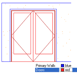 By creating unique components, you can use them for unique settings
such as Color, Lineweight, Linetype and so forth. By creating unique components, you can use them for unique settings
such as Color, Lineweight, Linetype and so forth.
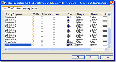
Illustrated to the right I show the same two Component
Names created in the steps above. If you recall, a Filter was set to find the Walls
and the Doors based upon a Color within a particular Context ( like a subdivision number
). After filtering, we get to set new Display Properties here as illustrated to the
right and left with the Blue Primary Walls and Red Doors.
If you expand on this simple example, you should find that
you can get some great results that come closer to how you have been drawing your
elevations in regular AutoCAD. |
 |
| Display
Properties - 2D Section/Elevation Styles - Hatches tab
This option only applies to Sections. |
|
| Display Properties - 2D Section/Elevation Styles - Custom
Display Component
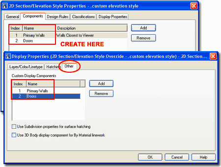
On the Other tab of the Display Properties dialog box you
will find the ability to Add Custom Display Components but these are not quite the same as
those Added under the 2D Section/Elevation Style Properties.
In the illustration to the right I show how Adding
Display Components on the 2D Section/Elevation Style Properties
dialog automatically Adds them to the Custom Display Components list on
the Other tab of the Display Properties dialog.
Though you can Add Custom Display Components on the Other tab of the Display Properties
dialog and even adjust Colors, Linetypes and so forth on the Layer/Color/Linetype tab,
they never show up as anywhere else where you might actually want to use them; like when
using the Modify Component... when Editing in Place. Therefore, I suggest that you
only use the Add button on the 2D Section/Elevation Style Properties dialog.
Use Subdivision properties for surface hatching
- this checkbox, when checked, will apply the same Display Properties to Surface Hatches
that are applied to the linework for different Subdivisions. In other words, if you
set up subdivisions so that lines are lighter in the back of an elevation, using this
option will use the same settings for Hatches. The only problem with this option is
that we usually want our Hatch Patterns even lighter than the linework so if you really
want great result with this option you have to spend a good deal of time configuring
Design Rules and the Layer/Color/Linetype settings.
Use 3D Body display components for By Material
linework - this checkbox, when checked, will apply the same Display Properties to
all Linework that is applied to the 3D Body Display Properties of the original object(s)
from which the Elevation or Section was derived. Like the checkbox option above,
this is another option that can be used to make the Elevation Object look more like the
Model. To me, this option is not typical since my preference for how Elevations
should look is quite a bit different from how I perfer my Model to look. |
 |
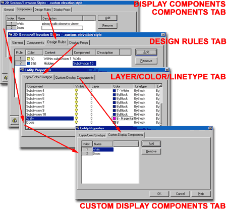
| 2D Section/Elevation Styles - Display Components - Relationship Map  Illustrated
to the right, is an overall map of how all the pieces come together for unique and custom Components. Illustrated
to the right, is an overall map of how all the pieces come together for unique and custom Components.
Illustrated to the left, is an example of how you can use
these unique Components to adjust the Colors and Lineweights of 2D Elevations to match you
want them to look by traditional means.
By using the examples illustrated, I was able to make the
Walls in Subdivision 1 darker, but not as dark as the Roof in Subdivision 1. I was
able to lighten all the Doors, Windows Openings and Window Assemblies so they didn't read
as dark as the Walls and Roof line in Subdivision 1.
Objects beyond Subdivision 1 can be controlled in a similar
fashion or simply be allowed to be lighter and monotone - an easy and effective solution. |
 |
| |
|
| 9Elevations - Materials |
9-14 ELEVATIONS |
| Surface
Hatch
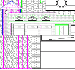 As discussed in Part 1 - Aec Setup
and Display, Materials offer two additional Display Property options that
have a dramatic impact on Elevations and Sections. The first option offers the
ability to apply 2D Surface Hatch Patterns on objects and the second option offers the
ability to apply 2D Bitmap Images on objects for Rendering purposes. As discussed in Part 1 - Aec Setup
and Display, Materials offer two additional Display Property options that
have a dramatic impact on Elevations and Sections. The first option offers the
ability to apply 2D Surface Hatch Patterns on objects and the second option offers the
ability to apply 2D Bitmap Images on objects for Rendering purposes.
In Section 9 we will look at the use of Hatch Patterns
across 2D Elevation Surfaces. For Rendering topics, see the Architectural Desktop
Presentation eGuide.
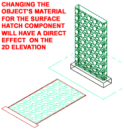
For 3D Elevation Objects, since there is no Style that
controls their Display Properties, their Display is derived directly from the Model
Display Representation and thus whatever Materials it is set to use, are the Materials
that you will see in the 3D Elevation Object.
For 2D Elevations Objects, there are several Display
Property controls that all have to work together in order to get proper results.
Illustrated to the right I show that the Layer/Color/Linetype tab of a 2D Elevation
Object's Display Properties has a Surface Hatch Linework Display Component that you can
turn On or Off. If you don't have any Surface Hatching assigned to the actual
Objects from which the 2D Elevation was derived, you will not be able to add it here.
Basically the you will need to decide on how you want to control the Display
Properties of the Surface Hatch: By Material or by the options on this tab ( such as Color
). |
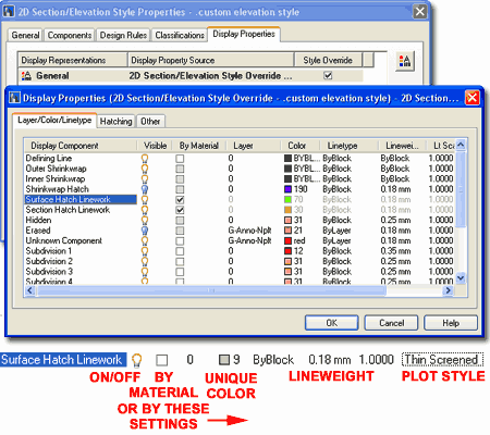 If you get stuck on weather or not to use the By
Material checkbox for the Surface Hatch Linework Display Component, consider how the Hatch
Pattern looks on your Model in Isometric. If you think the Color is fine then leave
this setting alone ( that's easy ), if you really need a different Color, for example,
then uncheck the By Material option and set the Color or other settings as you want the
Surface Hatch to appear when using this 2D Section/Elevation Style. |
| Adding a
Material to an Object Overview
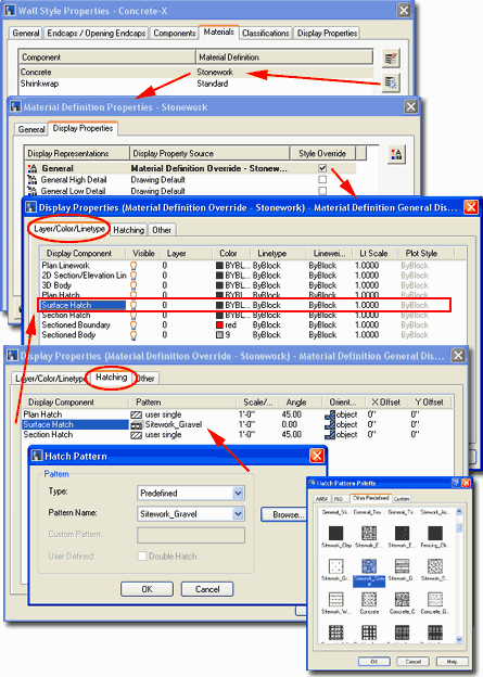
 Illustrated to the right I show the various dialog boxes used to add
or modify the Surface Hatch Pattern for a simple Wall Style ( Concrete - X ). The
steps shown are similar for most of the objects in ADT so you can use this approach to add
horizontal or vertical lines for siding, roofing or other needs on Walls, Doors, Windows,
Roofs and Slabs. Illustrated to the right I show the various dialog boxes used to add
or modify the Surface Hatch Pattern for a simple Wall Style ( Concrete - X ). The
steps shown are similar for most of the objects in ADT so you can use this approach to add
horizontal or vertical lines for siding, roofing or other needs on Walls, Doors, Windows,
Roofs and Slabs.
1) Use the Style Properties dialog box to
access the Style's Materials tab.
2) Add a New Material or Modify
an existing Component Material.
3) On the Material Definition's Display Properties
tab, use an Override for the Display Representation being used
to Generate your Elevation Object(s). In the illustration to the right, I show that
I have added an Override on the General Display Representation because
that is what my Wall Style is using in the default 2D Elevations. If in doubt, you
can add Overrides to as many of the Display Representations as you think you need
to. The Overrides are necessary because the Material Definition, like object styles,
uses the same Display Representations for all cases of use; i.e., if you don't use an
Override and set it to Bricks, that will become the default Hatch Pattern for the current
Display Representation and you could end up with Bricks where you don't want them.
4) Once you activate the Style Override, you should be
taken to the Display Properties dialog for the Material Definition
Override. On this dialog, you should find that the Surface Hatch Display
Component on the Layer/ Color / Linetype tab is turned OFF by
default. Turn this Display Component ON.
5) To set the Hatch Pattern
for this Material Definition, use the Hatching tab on the Display
Properties dialog ( same dialog as in step 4 ). For the Surface Hatch
Display Component, pick on the Pattern field ( image icon ) and you
should see the Hatch Pattern dialog where you can use a Predefined Pattern Name
( use the Browse... button ) to set a really nice pattern.
6) Close All dialog boxes and Refresh
any existing 2D Elevation Objects to see the new Surface Hatch Pattern. |
 |
Material
Boundary
| Keyboard |
2dSectionResultAddHatchBoundary |
| Mouse |
Select 2D
Elevation or Section Object, Right-click and select Material
Boundary > Add from the object specific pop-up menu. |
| Links |
Object Style
Properties - Materials Overview - for an overview discussion of Materials and Surface
Hatches. |
 Material Boundaries provide the
means to "Erase" or "Limit" Hatching
and Linework on 2D Elevations and Sections. This
means that you can define a boundary for where you want your hatch pattern across the
surface and/or the lines of the object as well. In essence you can think of this as
a Wipeout-like tool. Material Boundaries provide the
means to "Erase" or "Limit" Hatching
and Linework on 2D Elevations and Sections. This
means that you can define a boundary for where you want your hatch pattern across the
surface and/or the lines of the object as well. In essence you can think of this as
a Wipeout-like tool.
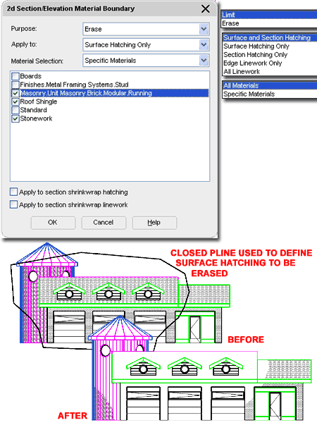
The concept is fairly simple to grasp: you draw a Closed
Polyline shape over your 2D Elevation or Section and use it to "Erase"
or "Limit" the whole or portions of it.
Illustrated to the right I show a Before
and After shot of a simple 2D Elevation Object with Surface Hatches
across most of it. In the Before shot, I show a Closed Polyline that can be used to
Erase or Limit any or all of the Linework and Hatches. On the 2D
Section/Elevation Material Boundary dialog, also illustrated to the right, I show
that I made specific choices for Purpose, Apply to and Material
Selection in order to produce the results illustrated by the After shot.
Purpose - this drop-down list offers the
ability to use the Closed Polyline as a Boundary that Erases the objects
within it or Limits them from going beyond it.
Apply to - this drop-down
list has five different options for what the Closed Polyline will affect: Surfaces and
Section Hatching, Surface Hatching Only, Section Hatching Only,
Edge Linework Only and All Linework. In the Before
and After shots, I used the Surface Hatching Only option to only affect the Hatch Patterns
but you can use the All Linework to create a Crop or Clip effect.
Material Selection - this
drop-down list offers the option to choose which Materials you want the Closed Polyline to
affect. By setting this drop-down list to "Specific Materials",
you open up the Materials List below it and are thus able to specify the Materials to be
affected. This means that you can, for example, "Erase" a Brick Hatch
Pattern while leaving a Spanish Roof Tile Hatch Pattern unaffected though it resides
within the Polyline.
Apply to section shrinkwrap hatching - 2D Sections
- see PART 15 - SECTIONS AND LIVE SECTIONS
Apply to section shrinkwrap linework - 2D Sections
- see PART 15 - SECTIONS AND LIVE SECTIONS |
 |
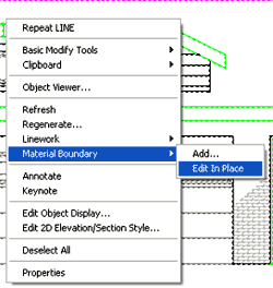
| Material
Boundary - Edit in Place Once you have
applied a Material Boundary, as outlined above, you can Modify it by using the "Edit
In Place" menu option illustrated to the left. This option will only be
available once a Material Boundary has been Added.
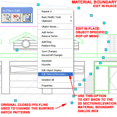
 Illustrated to the right I show an example of what a Closed Polyline
may look like when the Material Boundary "Edit In Place"
feature has been activated. For most, the In-Place Edit toolbar and Grips should be
concepts that are easy enough to comprehend: Save All Changes, Discard
All Changes, Grip Stretch to alter the shape of
Closed Polyline, etc. However, what may not be self-evident, is that once you are in
the "Edit In Place" Mode, you can Select the lightly Hatched Boundary,
right-click and invoke the object specific pop-up menu as illustrated to the right. Illustrated to the right I show an example of what a Closed Polyline
may look like when the Material Boundary "Edit In Place"
feature has been activated. For most, the In-Place Edit toolbar and Grips should be
concepts that are easy enough to comprehend: Save All Changes, Discard
All Changes, Grip Stretch to alter the shape of
Closed Polyline, etc. However, what may not be self-evident, is that once you are in
the "Edit In Place" Mode, you can Select the lightly Hatched Boundary,
right-click and invoke the object specific pop-up menu as illustrated to the right.
By using the options on the object specific pop-up menu,
you can Add or Remove Vertex Points, Rings
and even change the Display Properties of the Boundary as it is displayed
in the "Edit in Place" mode ( that's wild, isn't it ).
Of the group of options on the object specific pop-up menu,
the one you are most likely to desire is the Edit Material Boundary...
option which takes you back to the 2D Section/Elevation Material Boundary dialog
box used to create the Boundary in the first place. |
 |
| 10Elevations -
Customizing and Tricks |
10-14 ELEVATIONS |
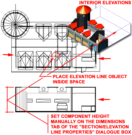
Creating Interior Elevations
| Links |
Elevation Marks - for how to
generate interior elevations directly off of the Interior Elevation Mark. |
In addition to creating Interior Elevations with the
Elevation Marks, you can also create them with either the Section Line object or the Elevation
Line object. Simply place the Section or Elevation line object inside the
space you want an Interior Elevation of and Generate your 2D Elevation.
Once you have an Interior Elevation, you will probably want
to narrow the focus of what is displayed since it probably looks more like a Section than
an Interior Elevation, at this point.
Adjust the Width of your
Elevation Line object ( using Grips or Stretch ) to match what you want in your Interior
Elevation ( see red arrows ).
On the Properties Palette for the
Elevation or Section Line Object, look for the Dimensions category,
change the "Use Model Extents for Heights"
to "No" and set the Height
value manually to match what you want in your Interior Elevation. You will also need
to set the Lower extension value to match your floor line height - most
likely zero.
Update your Interior Elevation. |
 |

 In ADT
Elevations and Sections are broken up into two separate tasks though they are basically
identical objects using nearly all of the same tools. This means that you can
actually use the Elevation Line Object to create Sections and the Section Line Object to
create Elevations. It's a bit silly, isn't it and we should really just think of
this type of work as creating Projections because you can use either object to do Interior
Elevations as well. In fact, you can also use the
  Most designers are familiar with the concept of
a 2D Elevation or Section so that part of this process is relatively self-explanatory but
ADT offers a new twist on this concept: 3D Elevations and Sections.
  Elevations, what's the big deal?
 Dimensions

 The Elevation Line object in ADT does not have a Style but you can
use Edit Object Display... to access its display controls. On the Object
Specific pop-up menu, illustrated left, select Edit Object Display... On
the Object Display dialog box choose a Display Representation, like Plan
and double pick on it or pick the Edit Display Props... button.

 Both
types are linked to the original drawing and thus can be updated to reflect your design
changes at any given time. This will be discussed below.


 Once 2D or 3D Elevations have been created, you
can Regenerate them to update for changes made in the model, change the
original selection set or make other changes offered on the Generate
Section/Elevation dialog - illustrated right. For 3D Elevations, the option
to use Styles is not available and for 2D Elevations, the option to save Edits to another
Style is only available if "in-place" editing has been done and if another Style
exists.


 Once you have activated the Edit in Place function for a 2D
Elevation, you can Select any part of that Elevation Object, right-click to see new
options on the object-specific pop-up menu: Modify Component and Edit
in Place with Discard Changes and Save Changes.


 The 3D Elevation object in ADT does not have a Style but you can use
the Edit Object Display... menu option to access and manage unique
display controls. On the Object Specific pop-up menu, illustrated left,
select Edit Object Display... On the Object Display dialog, illustrated to the
right, choose a Display Representation to modify or Override. Use the Override if
you don't want your modifications to apply to all 3D Elevation Objects in the current
drawing.


 Illustrated to the left, is another way to access the Display
Props tab; select the specific object, right
click on your mouse to invoke the object-specific pop-up menu and select Edit
Object Display... See discussion directly below.

 By creating unique components, you can use them for unique settings
such as Color, Lineweight, Linetype and so forth.

 Illustrated
to the right, is an overall map of how all the pieces come together for unique and custom Components.
 As discussed in
 Illustrated to the right I show the various dialog boxes used to add
or modify the Surface Hatch Pattern for a simple Wall Style ( Concrete - X ). The
steps shown are similar for most of the objects in ADT so you can use this approach to add
horizontal or vertical lines for siding, roofing or other needs on Walls, Doors, Windows,
Roofs and Slabs.

 Illustrated to the right I show an example of what a Closed Polyline
may look like when the Material Boundary "Edit In Place"
feature has been activated. For most, the In-Place Edit toolbar and Grips should be
concepts that are easy enough to comprehend: Save All Changes, Discard
All Changes, Grip Stretch to alter the shape of
Closed Polyline, etc. However, what may not be self-evident, is that once you are in
the "Edit In Place" Mode, you can Select the lightly Hatched Boundary,
right-click and invoke the object specific pop-up menu as illustrated to the right.
