When I set out to write the first eGuide it was based on one goal; to create something I could use for teaching that was better than the manuals I had purchased. At that time all I really wanted was a proper list of commands, dialog boxes and procedures for the tools offered in Architectural Desktop so my students could take notes and refer back to the material. The eGuides have since grown beyond what I had expected to do and often feel like a labor of insanity that will never be complete; they are like the architectural project that is in constant development. On the other hand, the joy of sharing to such a global audience only inspires me to reach for higher quality and more thorough information. Time and the limits of what one person can produce in his spare time are my primary obstacles at this time.
The Architectural Desktop 2005 Development eGuide is now moving into its 4th edition. The changes between ADT 3.3 and ADT 2004 were so massive that I had to rewrite the entire guide for ADT 2004. Because ADT 2005 is fairly similar to ADT 2004, I am only going to continue the updating process for those Parts that I intentionally left alone in the ADT 2004 Development eGuide. The first Part to receive attention is Part 2 - Layers.
Given the amount of work, the low return on investment and the fact that my interests are moving away from CAD and more into the practice of architecture, it is highly unlikely that there will be another update. I honestly don't know how other authors continue rewriting year after year.

Whether you are a continuing subscriber or a new one, I thank you for the support and enthusiasm that gives me the energy to continue plugging away at the writing night after night.
| Menu | Tools> Options |
| Keyboard | Options |
| Links | Options and AEC settings - for more information on installation options while installing. |
 The default installation of Architectural Desktop is fine for an office of
one but if you work in an office where two or more users need to share files, the default
installation is horrible. The problem with the default installation is that it does
not accommodate your network environment and thus you will need to restructure and
reconfigure the program after you have installed it on one machine.
The default installation of Architectural Desktop is fine for an office of
one but if you work in an office where two or more users need to share files, the default
installation is horrible. The problem with the default installation is that it does
not accommodate your network environment and thus you will need to restructure and
reconfigure the program after you have installed it on one machine.
There is enough technical and logistical information in doing a custom network configuration of ADT that it warrants another eGuide so I will not attempt to explain it all in one paragraph. For anyone who has configured AutoCAD or similar software for a networked environment, you can probably figure a lot of this out by analyzing how ADT works.
In simplistic terms, ADT utilizes a library of information to provide the users with everything from automatic layers to templates, objects styles and schedules. These library files need to be the same for the entire office and as they change ( by user contribution/customization) those changes should automatically be accessible to all users on the network. By moving some of the primary library folders, like Content, over to the Server and re-pathing ADT to find these moved folders and files, you will essentially centralize the library to one location. All other installations will thus no longer need their own library folders. The two primary tools for making all of this possible are ADT Profiles and ADT Desktop Icons.
When installing Architectural Desktop, you should find the "Remote Content Installation" option illustrated to the right. From this dialog box you can use the "Configure" button to access the "Remote Content and Support File Settings" dialog illustrated below right.
For offices that have two or more seats of ADT, I recommend that you push a good portion of ADT's Content over to a shared Server or workstation. Pushing too much of ADT's Content and Support files over to a Server can actually have a detrimental effect upon system performance so you may need to spend some time considering how to optimize your installation with respect to these options.
For most it is always best to select the "Custom" radio button and run through the list of features so you can remove items you don't need. The "Standard" installation option is fine for those in a hurry.
Remember that, as with most software programs these days, you can return later to Add installation features.
On the Installation Features dialog you can expand each major category to see the sub-categories. The categories cannot be expanded to a point where you can see the individual files so if you know that you only want a few of the files, you'll have to install the whole category and manually remove what you don't want later. This is rarely a real problem to deal with but in the past, for example, I often installed all the Metric Content so I could manually copy specific drawing files over to merge with the Imperial Content.
Illustrated to the right I show that I have placed an "X" next to categories that most U.S. based firms are likely to find unnecessary. Tutorials can be benefitial if users actually use them but I find that they are rarely used. If you use the Server option for ADT Tutorials on the Remote Content folder ( see above ), you can install all of them to one point.
If memory is not a concern in your office than there really is no reason to limit yourself. You might as well install everything except for that wacky "French-Canadian Dictionary" ;)
While on the subject, the New Features Workshop is surprisingly good this time around and I believe that most user will find it fun to run through the Flash animations.
The core program files still need to be installed on the local drive, even for Network License Users, and unless you see something profoundly incorrect in the default "C:\Program Files\..." path, the default should be fine. Though you can specify other Path Locations and Drives, routing the core files to a Server is not the way to go. Don't mistake this path with those set earlier for common Content and Support Files.
For a default Text Editor I prefer the smaller of the two illustrated: Notepad. If you attempt to Open an AutoCAD or ADT support file that is too large for Notepad, you will find that Windows uses Wordpad instead. For those who don't edit .mnu, .lsp and other files, what you are setting here is not for work done in AutoCAD or ADT but for the user customizable files that run in the software.
For Product Shortcuts, you are likely to want the Architectural Desktop and Viz Render shortcuts but you may need to think about the AutoCAD shortcut for a minute. I like having it because I can switch to it doing support for non-ADT users. In some offices having may prove to be a problem because users might use it instead of the ADT Icon. And, they are likely to do so simply because the default ADT Profile is so stripped of common menus that it's difficult to adjust to.
The last dialog in the installation setup group should report that all went well and you may now use the Finish button to exit.
| Topic | Architectural Desktop 2005 CD |
| Location | Disk 1 of 3 |
| Links |
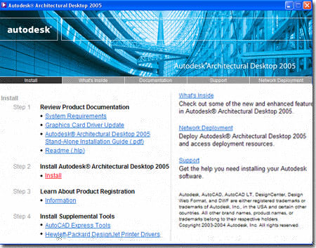
 Though it seems quite obvious, I do have to remind each and everyone of you
that you should explore the installation CD for options and features that
are not part of the default installation process. Of particular importance,
are the
Express Tools that many users think of as the best improvements ever
made. You can install them from Step 4 on the ADT Install page ( see
right ) or by visiting the Disk 1 Folder as illustrated to the left.
Though it seems quite obvious, I do have to remind each and everyone of you
that you should explore the installation CD for options and features that
are not part of the default installation process. Of particular importance,
are the
Express Tools that many users think of as the best improvements ever
made. You can install them from Step 4 on the ADT Install page ( see
right ) or by visiting the Disk 1 Folder as illustrated to the left.
You will also find the Object Enabler for ADT 2005 objects on Disk 1 (see left). This installation feature is for AutoCAD 2005 and other Flavors that are not ADT-based ( this excludes ADT core and Building Services). The enabler is required for non-ADT users to read the ADT objects as native objects rather than Proxy Objects.
This means that they can do minor editing such as Moving, Copying, Rotating and Deleting but higher levels of Modifications are not possible. You can send this installation file to sub-contractors or have them acquire it by visiting the Autodesk website ( which I recommend so they get the most up-to-date version).
| Menu | Insert> Detail Component Manager... |
| Keyboard | DtlCompManager |
AEC Details have come a long way since the first release of ADT and are now fully integrated into Architectural Desktop under one compact Detail Component Manager dialog (see right).
The Objects the detailer creates are 2D and consist of Lines, Plines, Hatch Patterns and a few other primitive Object Types (most are assembled into Blocks). Linework is Color Coded and Keyed according the current Layer Key Style settings. Options and settings for Details are available on the Properties Palette.
The Objects available under the Detail Component Manager come from an Access-readable .mdb database file that can be edited with Access, Excel or directly in the Detail Component Manager. This database holds information such as sizes, numbers, Block Names and so forth. This information is passed on to a corresponding .xml file that filters the data and imports a Block that matches the data. These Blocks come from drawing files stored with the Detail Databases. You will also find a corresponding Keynote Database that is also in an Access-readable .mdb file format.
Note:
Be aware that none of the .mdb files are set to read-only by default and
thus users can easily modify existing values that may or may not reflect
reality. At minimum, I recommend keeping a back-up copy around just in
case someone really hacks at the Details without thinking about what they
are doing.
One of the first acronyms I like to write on the ink board in beginning ADT classes these days is "K.I.S.S." (Keep It Simple Stupid ). Though ADT has the ability to create some rather complex solutions such as Wall Styles with a multitude of internal components, hatches, linetypes and colors, I have found that these complexities only make the process of learning how to use the tool all that much more difficult. What this has also made me focus on is the beauty of how most offices already use AutoCAD to create their drawings.
Most offices have had years of experience with project file organization and assembly and those years are very important because they define a methodology that has proven itself. Just because you are using a new set of tools, basically a new program, does not mean that you should abandon methods that work and this is my current philosophy on consulting, training and writing;i.e., make ADT conform to your office rather than making your office conform to default ADT.
Below I will briefly elaborate upon some of the ADT tools and settings that you can adapt to work more like your office currently works. In Part 3 I will briefly elaborate on some of the common office methodologies that you should, most likely, continue to employ when using ADT.
Architectural Desktop comes with a large list of template files that you can use to get projects started. All of the discussions in the Architectural Desktop eGuides have been written based upon the "Aec arch (Imperial - intl).dwt" but it is not necessary to use this template file or any of the other template files.
If you choose not to use any of these predefined template files there are a few important aspects of the predefined template files that you will need to incorporate into your own template files for good results. There are two ways that you can incorporate these default settings into your own template file(s); one way is to take a predefined template file and purge it of all unnecessary information and the other way is to configure and import settings as required. The latter method requires more work and knowledge of how ADT template files are configured but is also more likely to produce a very clean template file for your needs.
Personally, I am not a fan of the predefined template files that come with ADT because they have been designed more to show what is possible than how to work in a professional production environment. On consulting jobs, one of the first things I do is purge the "Aec arch (Imperial - intl).dwt" template file of extraneous data and save it as "office standard.dwt".
| Menu | Desktop>Style Manager... |
 |
|
| Keyboard | AECSTYLEMANAGER |
| Links | Part 1 - Display, Section 5 - Object Style Management - for more information on working with the Style Manager. See also the various different Parts on Objects such as Doors, Walls, Roofs, etc. |
One of the biggest problems with the predefined template files that come with ADT is that they contain long lists of AecObject Styles which behave like Blocks. This means that if a user decides to Add a Door, for example, the Door Style they choose will be extracted from the drawing file ( template file, really ) and not from the office library. This is exactly analogous to taking an office Block Library and dumping it into your office template file so users don't have to look to the Office Library Folder for the latest Block. But, what happens if the Library is in development and being refined for the office? Do you see the problem?
Therefore, it is far better to force users to Import AecObject Styles from the office library on an as-needed basis. This guarantees that they are always getting the most up to date Styles and see the most up to date Style options.
| Menu | Desktop> Display Manager... |
|
|
|
| Keyboard | DISPLAYMANAGER |
| Links | Part 1 - Display - for the whole story on Display Configurations and how they are necessary for proper display of objects in various views. |
If you create your own template file "From Scratch", the need to address Display Configurations will probably prove more critical than when Purging an existing predefined template file. In either case, you can use the Style Manager Window, illustrated to the right, to Purge or Import Display Configurations from any of the predefined template files.
If you do not Import a good set of Display Configurations, you are asking for a bit of trouble because these Display Configurations are the key ingredient in getting objects to look architecturally acceptable for different views such as Reflected Ceiling Plans, Elevations and 3D Models. You can, of course, create your own in your own template file and not worry about Importing them but that would take a bit of time. It is probably easier to Import and Modify than create from scratch.
| Menu | Desktop>Drawing Setup... |
|
|
|
| Keyboard | AECDWGSETUP |
| Links | Part 1 - Display, Section 2 - Drawing Setup Dialogue boxes - for more information on how to set a drawing up. |
The final aspect of creating your own template file that is imperative for good results with ADT is the Drawing Setup. Units and Scale should be self-explanatory but it is the Layering that really needs to be addressed.
In order for ADT to key your objects correctly as you use them in your template file, a Layer Key Style file must be set. If no file is set, you will end up with all of the ADT objects on Layer 0 and Colored according to that Layer ( usually White ). You may have experienced such results when mixing new ADT objects with older files drawn with AutoCAD R14.

| Menu | Desktop> Layer Management> Layer Key Styles... |
 |
|
| Keyboard | LAYERKEYSTYLE |
| Links | Part 2 - Layer Management |
A good number of the offices I visit feel that they should automatically adapt to the AIA Layer Format supported by ADT but the fact of the matter is that you can just as easily continue to use any layer system you have developed yourself. You can argue that all offices should use the same layer standards to make file exchange more streamlined but I find that argument so old and trite that it smacks of limited imagination. I'll leave this debate to those who love to police such matters and focus on what you can do instead.
You can create your own Layer Names in ADT and you can also assign your own Colors to those Layers. At the very minimum, at least assign logical colors to the AIA Layer standard. The AIA standard, for example, uses Color 50 for A-Wall which may make sense to their organization but I don't know any user who doesn't confuse that Color with Color 2 ( Yellow );so why not make it Color 2.
Let's be realistic here, the Colors serve two purposes: if Color Tables are used, they define a Line Style and they help the designer read their drawings. Most offices only use a handful of colors so why try to take on all of those strange ones that come by default.
Inside Object Styles, you will find another level of Layer and Color complexity that you will also have to address as you tailor this product to work for your office - see Entity Properties - Component Layers for an example of layers inside objects.
| Menu | Design> Walls> Cleanup Group Definitions... |
 |
|
| Keyboard | Wall <enter> CL |
| Links | Part 3 - Walls |
In most offices I find that two lines are satisfactory for representing Walls, especially if the project is large and printed at a small scale. If this is the case in your office, why clutter your work with Wall Components that force a designer to worry about such issues as Baselines, Inside and Outside and proper Cleanup Priorities. I recommend focusing on just getting two lines to work the way you want before trying to get fancy. The first place to get fancy is in details where you may want to show a portion of a Wall that addresses surface materials, vapor barriers and so forth; just explore there first before adding such complexity to the actual plans.
Even with a double line Wall Style, you will find that Cleanup issues pop up all of the time. For situations where Cleanup issues cannot be solved with simple Grip adjustments, Trimming or Extending, you should develop alternative solutions that rate as "acceptable for now". Of course, Explode is not one of those solutions because Exploded Walls lose their "intelligence" and become dumb lines that don't react to other objects. But, you might try creating a separate Cleanup Group Definition so you can just take one or more troublesome Walls and assign them to this group.
Separate Cleanup Groups may not produce clean "T" or "X" intersections but you know what, it doesn't take an hour of frustration nor does it really matter that much on the final prints; if pochéd, it will hardly be visible. The idea is to remember how we all have invented "work-arounds" with AutoCAD over the years to provide the types of drawings old hand-drafters wanted back when that transition was taking place. Things have changed, most accept drawings with dimension lines crossing each other now and that was a classic "no no" in the days of hand drafting. The same types of changes in presentation will now become true as a result of working with "intelligent objects".
| Menu | Insert> Xref Manager... |
| Keyboard | Xref |
Ask yourself how you manage multiple floors now and that will most likely be the way you should manage them with ADT. I, for one, am a huge fan of Xref's and cannot stand files where people try to cram as much into them as possible by using long lists of Layer Names ( so if you are one of those types, don't send me any of your drawings <G> ).
You may not want to go as far out with this technique as I do but you will need to use Xref's in project teams when trying to manage multiple floors in ADT. Not only will it be necessary for multiple floors, but I find that it is necessary for separate tasks like Reflected Ceilings, Electrical, Mechanical, Furniture, etc, etc. I find that if you keep the base model as pure and simple as possible the less you have to fight with it and the more likely it is to remain pure and cohesive. Of course jobs vary and I typically try to focus on larger projects where more problems are likely to occur. My feeling is that if it works on large projects, chances are it will work on small ones too but the reverse is rarely ever the case.
Since ADT has some logistical problems working through Xref's there are limits to my methods. One striking limit that really drives me crazy is that you have to put any and all Tags in the base model in order for them to hold the Schedule Data that you will want for generating Schedules. What's really ironic though is that the Schedule generating tool has no problem working off of Xref's as long as the Tags have been placed in the base files. Dimensions are another problem for Xref users and if you use the AEC Dimension tools you will need to use them in the base files as well. Basically you can expect that any tools that need to react to native objects in ADT will not work over Xref files.
 If I have offended you then here's my historical
journey down project file management lane: I started in 1985 and created layer names based
on numbers because the first one I saw was 0 so it made sense to call the next one 1.
Eventually I got smart enough to figure out that no two people would really see
numbers the same way so I started using short letters and words only to find the 8
character and 31 character limits. I invented systems that look much like the AIA
layer of today and then tried to get really fancy and stuff everything in one file.
I built an amazing layer system with macros and layer controls that made the process of
creating residential construction documents seem like magic. Then I started
consulting for bigger and bigger firms until I worked on some of the largest projects in
the world and quickly learned that simplicity equals sanity and Xref's can be a tool more
wonderful than layers. You see, Xref's are basically just containers of Layer Names
so they act like groups and you can use Draworder, for example, on a whole Xref.
Xref's can be Unloaded and Reloaded very easily and they can also be Clipped ( even in ADT
). Xref's do come with their own problems and limitations but overall I find them
the smartest way to manage projects.
If I have offended you then here's my historical
journey down project file management lane: I started in 1985 and created layer names based
on numbers because the first one I saw was 0 so it made sense to call the next one 1.
Eventually I got smart enough to figure out that no two people would really see
numbers the same way so I started using short letters and words only to find the 8
character and 31 character limits. I invented systems that look much like the AIA
layer of today and then tried to get really fancy and stuff everything in one file.
I built an amazing layer system with macros and layer controls that made the process of
creating residential construction documents seem like magic. Then I started
consulting for bigger and bigger firms until I worked on some of the largest projects in
the world and quickly learned that simplicity equals sanity and Xref's can be a tool more
wonderful than layers. You see, Xref's are basically just containers of Layer Names
so they act like groups and you can use Draworder, for example, on a whole Xref.
Xref's can be Unloaded and Reloaded very easily and they can also be Clipped ( even in ADT
). Xref's do come with their own problems and limitations but overall I find them
the smartest way to manage projects.
| Menu | Documentation> Elevations> Add Elevation Line |
 |
|
| Keyboard | BldgElevationLineAdd |
| Links | Part 14 - Elevations |
| Part 15 - Sections |
We can start with the fact that you already know how to draw Elevations and Sections in AutoCAD so whatever ADT offers to speed up the process is great; as I have always told clients, "just give me accurate vector based drawings and the rest is easy for me".
In order to get an accurate elevation, you will need to Xref all of the model files together into one master composite file ( assuming you don't draw everything in one file ) where you stack floors, roofs and anything else according to the correct elevation heights.
Once you have a good Composite file, you can use the Elevation and Section tools to generate 2D projections that will remain linked to the Xref file. If changes occur to the base model files, you can request an Update for your Elevation and Section projections. Eventually though, you will most likely need to Explode the linked projections and finish them off in the traditional 2D linework way. There's a great tool called "OverKill" from the Express tools ( Express > Modify > Delete duplicate objects ) that will remove any redundant lines generated in the 2D Elevations and Sections so you won't have to deal with recurring linework (lines over lines).
One of the easiest traps you can get caught in when working with 3D objects and tools is that of Modeling. Working in 3D is so incredibly captivating that it is very easy to lose perspective ( pun intended ) on what you are really attempting to produce: construction documents ( for most ). In my opinion, a healthy way to look at ADT is to see 3D Modeling as a byproduct of good CD work. However contrary this may be to the buzz and hype coming out from most AEC CAD vendors, the reality is that Modeling a building completely would take just as long as constructing it and most of us don't have the luxury of working that long on our jobs. Non-architects who work in software don't seem to comprehend the art of Construction Documents and the amount of information that is left to interpretation ( for some it is less and for other's it is more ). The reality of the architectural practice is that everything cannot be documented and yet the documents must cover everything in some magical way ( that's the art ).
Using a Mechanical Engineering paradigm for architecture is a mistake and a lot of AEC software is being developed along that line of thinking. My advice is not to get caught up in trying to make the perfect model but focus on getting good construction documents and be happy for any use you can derive from the resultant 3D Model.
Subscribers have often written about odd experience in their ADT that causes effects that they are either not accustomed to or have not knowledge of changing. Recently I experienced a similar observation and have decided to start tracking variables and settings that can cause undesirable working conditions in ADT. I may move this section to an Appendix or other location but for now this seems to be the best location.
Cmddia - turns the command dialog boxes on and off.
Filedia - turns the file dialog boxes on and off. You will know when this is a problem when you use Open or New and find no dialog box option ( set to 1 - on ).
Dragmode - turns the dragging effect on and off and can result in no Side Marker on Walls when Adding or Stretching them.
Pickfirst - turns on or off the ability to select objects before executing a command.
Rememberfolders - turns on or off the ability for AutoCAD/ADT to return to the previously accessed folder rather than the default target folder. ( best when set to 0 - off ).
FacetDev - controls the facetting of curved shapes created by architectural desktop. This variable is similar to FacetRes that controls facetting on Solids. FacetDev is set to .5 by default. The lower the deviation along the curve, the smoother the curve and the longer it takes for shades and renderings; i.e., use a smaller number for better curves. In some cases, the FacetDev has to be set prior to doing certain operations because some ADT objects get locked to the setting at the time of creation.
...please feel free to contribute your own stories and theories on a successful implementation.