| 1Curtain Walls Access |
1-5 CURTAIN WALLS. |
Curtain Walls Toolbar
How do I get this
toolbar?
You can also acquire access to these commands from the Alternate Design
pull-down menu. From
the
Alternate Design pull-down menu, pick Curtain Walls > and
cascade to the right for commands. |
 |
| Curtain Walls pull-down menu
 The
mother of all Grids in ADT is the Curtain Wall Object. Users all over
the world are finding new ways to employ this tool for things I am sure the
programmers never dreamed of. I have even attempted to produce a suite
of parametric furniture but due to display limitations for this Object Type,
these currently only work in 3D Views. The
mother of all Grids in ADT is the Curtain Wall Object. Users all over
the world are finding new ways to employ this tool for things I am sure the
programmers never dreamed of. I have even attempted to produce a suite
of parametric furniture but due to display limitations for this Object Type,
these currently only work in 3D Views.
The Curtain Wall Object is a sophisticated
grid tool designed to work much like a Wall Object and thus does not support
horizontal grids (as viewed across the XY Plane). Though you can rotate a Curtain Wall so that it
matches any plane in space, such as Roof Planes, getting it to display
correctly in Plan is rather difficult and sometimes impossible - but don't
let that stop you from trying. Within the Grid you have a
spaces called Infills ( Cells ) that can in turn hold other Objects
such as Curtain Wall Units, Door/Window Assemblies, Doors
and Windows.
|
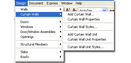
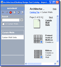
Illustrated above I show the alternate
Design pull-down menu for Curtain Walls and to the left I show the Content
Browser to remind you of where to look for predefined Curtain Wall Styles.
Since there really aren't very many predefines styles and since it is highly
unlikely that your design criteria has been configured, just dive in and
learn how to create your own Styles.
You can convert a Wall object into a Curtain Wall object.
Below is the main command line read-out for this tool:
Command: CurtainWall
Curtain Wall [Add/Convert/Reference/Modify/Properties/Styles/Interference]:
You can also specify the option that you want; such as CurtainWallAdd
or CurtainWallStyle |
| 2Loading Curtain Wall and
Curtain Wall Unit Styles |
2-5 CURTAIN WALLS |
| Opening
Curtain Wall Styles in the Style Manager
The first subject we will cover is how to
get other ADT Curtain Wall Styles than "Standard". On a local installation of ADT you should find,
within the ADT folder, the following sub-folder structure ( see image below left ).
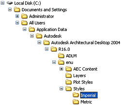 Both
the Imperial and Metric folders contain similar Styles
folders within which you will find one Curtain Wall Style drawing file. Both
the Imperial and Metric folders contain similar Styles
folders within which you will find one Curtain Wall Style drawing file.
On
a Network based installation of ADT, these Curtain Wall Styles should be on a captured
drive (like "G:\offices standards") or similar location with a similar folder
structure to that illustrated left (Content >> Imperial >> Styles >> Curtain Wall & Curtain Wall Unit Styles
(Imperial).dwg or Curtain Wall & Curtain
Wall Unit Styles (Metric).dwg ).
In a very customized office scenario, this file may not even be present and others
may have been designed for the wall styles your office prefers (in this case, see your CAD
manager). |
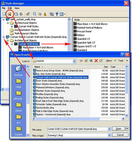
Illustrated
above, I show how you use the Style Manager, filtered for Curtain
Wall Styles, to Open one of the Curtain Wall Style files from
ADT's Styles folder. The process is much like Opening a drawing for
editing. |
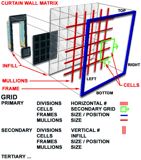
| Curtain Walls - Overview of Structure The Curtain Wall object is arguably the most
complicated object in ADT. One of the reasons I feel that I can safely state this is
that a Curtain Wall can incorporate nearly every aspect of Architectural Desktop. It
employs everything from Automatic Layer Keying, unique Display Representations and a
complex Style Structure to an open door for customization that allows you to associate
nearly every other form of ADT object within it. It is, in the simplest terms, a
Matrix.
 To begin understanding this object, my advice is
to first visualize it as a 2 dimensional grid in 3D space; in other
words, a grid standing up in the Z-axis instead of lying in the XY plane. In its
most simple form, it can be a single Frame with one Cell
inside. The complexity comes from adding more Cells, altering those Cells and
nesting other objects within those Cells as Infill, but at all times, the Curtain Wall is
still a single Frame. If you draw a Curtain Wall one unit long or 100 units long,
there is still only one Frame there. To begin understanding this object, my advice is
to first visualize it as a 2 dimensional grid in 3D space; in other
words, a grid standing up in the Z-axis instead of lying in the XY plane. In its
most simple form, it can be a single Frame with one Cell
inside. The complexity comes from adding more Cells, altering those Cells and
nesting other objects within those Cells as Infill, but at all times, the Curtain Wall is
still a single Frame. If you draw a Curtain Wall one unit long or 100 units long,
there is still only one Frame there.
|
 |
| 3Adding Curtain Walls |
3-5 CURTAIN WALLS. |
Add Curtain Walls
Properties Palette
| Alt.Menu |
Design> Curtain
Walls> Add Curtain Wall... |

|
 |
| Keyboard |
CurtainWallAdd |
| Links |
|
 The Add Curtain Walls
Properties Palette is a
deceptively simple interface because it appears as easy to work with at the
one for Adding Walls but the reality is that there is a whole world of
complexity behind the
scenes; within Curtain Wall Styles. The Add Curtain Walls
Properties Palette is a
deceptively simple interface because it appears as easy to work with at the
one for Adding Walls but the reality is that there is a whole world of
complexity behind the
scenes; within Curtain Wall Styles.
Once you have loaded your Curtain Wall Styles, you can
begin to Add them. On the Add Curtain Walls
Properties Palette, use the Style drop-down list to pick your style.
Base Height - total height for your Curtain Wall. This is an
interesting topic that I have to work with for some time before providing more advice.
Currently, if you decide to build an entire face of a high-rise with one Curtain
Wall, you will be encounter problems if you intend to break that Curtain Wall up for each
floor. I have decided to see it two ways: one is a Curtain Wall for Design Study and
the other is one that is used for each floor and each file with a height equal to each
floor. I use Xref's to bring all of the floors together. If Height is red then your typed in value is higher
or lower than what has been set by the style; if Height
is blue, then the typed in value is equal to the value set by the style and if Height
is black, then the Style has no preset value.
Straight - pick points just
as you would with a line or a regular Wall object. If you Start and Stop in a linear
path, the Curtain Wall does not glue together as one so you will end up with a series of
Curtain Walls. This may or may not be desirable.
|
 Curved - pick a base point, a
second point where you want to "pull" the curved Curtain Wall through ( like the
midpoint of an Arc ) and then pick the last endpoint. This can be tricky to control
and it is often easier to use an Arc that you Convert into a Curtain Wall. |
| Adding Curtain Walls - Examples 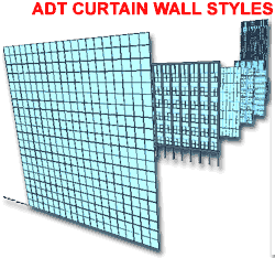 You can open the Curtain Wall & Curtain Wall Unit Styles
(Imperial).dwg or Curtain Wall & Curtain
Wall Unit Styles (Metric).dwg to see ADT's full set of Curtain Wall
Styles as illustrated left. Opening this file and using the 3D Orbit tool to view it
in Shaded mode will be a good test to see how your machine and graphics card will handle
working with Curtain Walls. You can open the Curtain Wall & Curtain Wall Unit Styles
(Imperial).dwg or Curtain Wall & Curtain
Wall Unit Styles (Metric).dwg to see ADT's full set of Curtain Wall
Styles as illustrated left. Opening this file and using the 3D Orbit tool to view it
in Shaded mode will be a good test to see how your machine and graphics card will handle
working with Curtain Walls.
Though
ADT's Curtain Wall Style have been designed to span several floors at one time, this is
not how we have been using them; primarily because we work with floors as separate files
and Xref them together to create the full model ( when needed ). If you attempt to
create a full high-rise model with one curtain wall, there is no way to break it up
automatically for each floor. Therefore, you can think about Curtain Walls as
serving two primary functions: as a full height massing study element and as a highly
detailed floor height ( one floor at-a-time ) element.
|
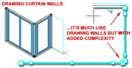 Since Curtain Walls can prove to be rather complex and difficult for people to
get going with, we have found that allowing users to simply create a regular Wall object first and then converting it later,
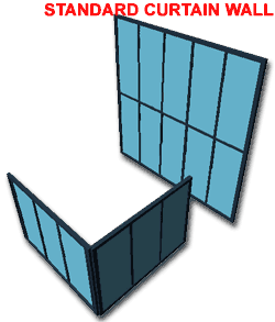
keeps a job going without early interruptions. As you can see from the illustration
above, even the "Standard" Curtain Wall Style can cause project
delays due to simple, but complex, matters of mullion spacing and corner cleanup issues. |
| 4Converting to Curtain Walls |
4-5 CURTAIN WALLS |
Converting Walls to Curtain Walls
| Menu |
Design> Curtain
Walls> Convert Wall to Curtain Wall |

|
 |
| Keyboard |
CurtainWallConvertWall |
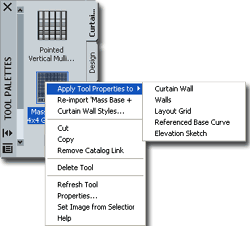
| Palette |
Select
Curtain Wall on Palette, right-click to Select
Apply Tool
Properties To and cascade over to Layout Grid. |
| Links |
Wall Styles - for information on
how to create a wall style. |
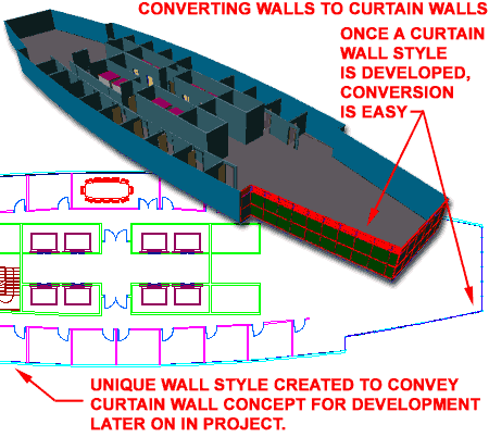
 Converting Walls to Curtain Walls is so
painless a process that I highly recommend this approach during project development.
Since Curtain Wall Style design can be such a time consuming process a designer can
often get caught up in something that isn't as important as it appears. For some
drawings, a slightly modified Wall Style could probably serve as a curtain wall
(especially if elevations are not going to be derived automatically). Converting Walls to Curtain Walls is so
painless a process that I highly recommend this approach during project development.
Since Curtain Wall Style design can be such a time consuming process a designer can
often get caught up in something that isn't as important as it appears. For some
drawings, a slightly modified Wall Style could probably serve as a curtain wall
(especially if elevations are not going to be derived automatically).
Illustrated to the right, I show a single floor of a
high-rise in early development phase. The core and some offices have been roughed
out but now tests need to be done on a true Curtain Wall System. Originally, a
simple Wall Style had been used to create the Curtain Wall but now
refinement can take place by using the Convert Wall to Curtain Wall routine. When
you convert Walls, you will be asked two important questions: baseline alignment
and "erase layout geometry". You will also, of course, be
asked which Curtain Wall Style you want to use.
Curtain wall baseline alignment [Left/Right/Center]
<Baseline>: - it is obvious from these four options that you can justify
according to one of them, but the question is which one. My tests, though
inconclusive, show that it doesn't matter because the conversion process reads the
original justification of the Wall being converted.
Erase layout geometry? [Yes/No] <N>: - this seems like a simple enough
option but if you do Erase your geometry and you want it back for future conversions when
testing other Curtain Wall Styles, you will have to create these walls again. My
suggestion is that if you anticipate lots of curtain wall testing, keep this set of walls
on another layer and simply turn them off. |
Note:
On this particular exercise we discovered two major problems that you may want to know
about. 1) In working with curved Walls,
Doors and Windows will have significant problems justifying correctly if they happen to
land right where curved wall segments join. You can try the WallJoin command but we still
have not found an adequate solution for this problem.
2) In working with curved Walls
and converting them to Curtain Walls, you may find that
Mullions and Frames do not line up correctly despite any efforts made to correct this
problem in the Curtain Wall Styles. We have yet to find an adequate solution for
this problem. |
|
| Converting Linework to Curtain Walls
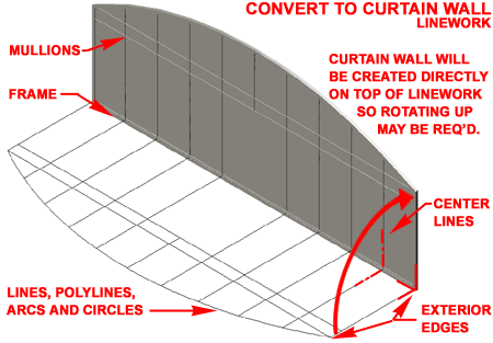
To convert Linework into a Curtain Wall, all you have to do
is draw the elevation lines for the Frames and Mullions using
Lines, Arcs, Plines and even
Circles. When drawing the frames, ADT will convert the lines for frames by
interpreting them as the exterior edge ( not as centerlines ) When drawing the mullions,
ADT will convert the lines for mullions by interpreting them as the centerlines.
Though this may seem like one of the easiest and fastest methods for
creating custom Curtain Wall Styles, it is actually a rather horrible
offering because the end product is virtually unchangeable. As a Style, you
will find the Primary Grid uses your linework as a "Custom Grid" that you
cannot modify.
Note:
When you have converted linework to a Curtain Wall, the Design Rules
are automatically set to the Object instead of a Style. To Save
the New Curtain Wall as a Style, use the
Save to
Style... context menu option and create a New Style Name.
|
Though you can modify the Infill, Frames and
Mullion sizes and even use Overrides for other types of modifications, I
think it best to see this option as one you use when desperate for a
solution. |
| Converting
Layout Grids to Curtain Walls
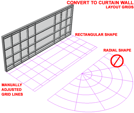
To convert a Layout Grid into a Curtain Wall, you simply
need to create a Layout Grid and then use it as a guide to form how you want your Frames
and Mullions with respect to dimensions and proportions. This is similar to the
technique of using linework, as discussed above. See the discussion for Converting Layout
Grids to Window Assemblies for more information. |
 |
Referencing Curtain Walls
| Menu |
Design> Curtain
Walls> Reference Curtain Wall |

|
 |
| Keyboard |
CurtainWallReference |
| Links |
|
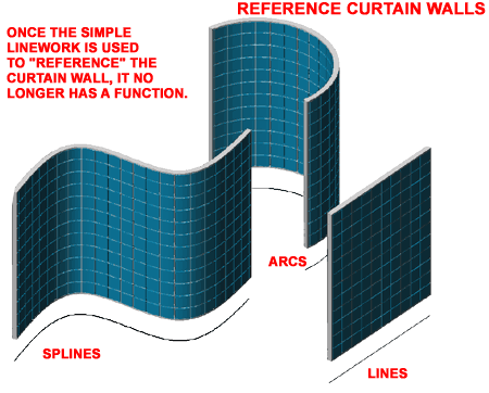
The Reference Curtain Wall tool provides you with a way to
derive a Curtain Wall from a simple object like a Line, Pline, Arc or even a Spline.
The term Reference can be misleading when in fact all you are doing is using the
simple object shape as a path to form the Curtain Wall Style off of. This tool is
similar to Converting Walls to Curtain Walls, discussed above. |
 |
| 5Modifying Curtain Walls |
5-5 CURTAIN WALLS |
Modify Curtain Walls
Properties Palette
| Alt.Menu |
Design> Curtain
Walls> Curtain Wall Properties |

|
 |
| Keyboard |
CurtainWallProps or -CurtainWallModify |
| Links |
Tools -
for how to set miter angles automatically by selecting two curtain walls. |
The Modify Curtain Walls tool opens a
dialogue box almost identical to the Add Curtain Wall dialogue box. You can change
the Style, change the Height or use the Properties
button to access more advanced options to change.
For more extensive editing options, use the Properties
button on the Modify Curtain Walls dialogue box - see illustration, right.
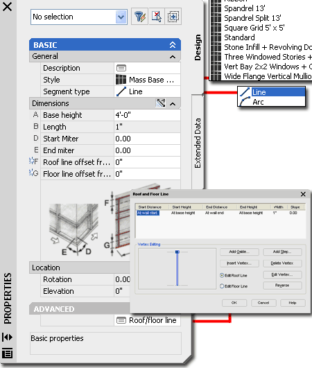
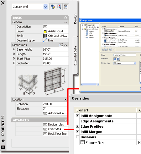
DIMENSIONS A - Base Height - this value can be very
confusing if you look at the image on this dialogue box ( A ). In
most cases, the measurement reflects the same height as you would expect from a Wall
object; from base to top ( bottom of frame to top of frame ). There is an option on
the Defaults tab of a Curtain Wall Style to create Offsets
for a Curtain Wall where A - Base Height can then become a value between
these Offsets - see Curtain Wall Styles - Defaults tab.
B - Length - this value represents the
total length of a contiguous curtain wall segment and can just as easily be Stretched with
Grips or the Stretch command.
C - Radius - this is the radius value for
curtain walls that have been drawn with the Curved option. Unfortunately, once a
segment has been drawn, you cannot change it to a curved segment and that is why you may
find this value field unavailable.
 D - Start Miter Angle - the two miter angle options will accept
both positive and negative values, so if you see your miter cut going in the wrong
direction, try the opposite angle value. The miter angle only applies to the top and
bottom Frame components and thus will not automatically cut the right or left Frame or any
Mullions or other components within a curtain wall. To create mitered glass, you
have to remove the right and/or left Frame component. To miter the right and/or left
Frame component, you have to create a right and/or left Frame component that is already
mitered ( usually done with a Profile Style ). D - Start Miter Angle - the two miter angle options will accept
both positive and negative values, so if you see your miter cut going in the wrong
direction, try the opposite angle value. The miter angle only applies to the top and
bottom Frame components and thus will not automatically cut the right or left Frame or any
Mullions or other components within a curtain wall. To create mitered glass, you
have to remove the right and/or left Frame component. To miter the right and/or left
Frame component, you have to create a right and/or left Frame component that is already
mitered ( usually done with a Profile Style ).
E - End Miter Angle - see comments for
Start Miter Angle, above. |
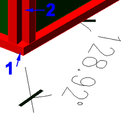
 1. In the illustration to the left, I show that in complicated situations you will
have to calculate the miter angles to make the top and bottom frame components meet
correctly. If you don't calculate this value, you will either see a gap or overlap.
Also, remember that in a case as illustrated, one angle is positive and the other
is negative ( 128.92 - 90 = 38.92 and -38.92 = 328.08 ).
2. The really frustrating thing you
may encounter is that this miter work does not affect the Vertical Frame components (
those that you actually see in Plan view so you will have more work to do on them ).
Hot Tip
Use the "GridAssemblySetMiterAngles" command to
automatically calculate the miter angle between two adjacent Curtain Walls. You can
also acquire access to this tool on the object specific pop-up menu. |
|
| Curtain
Wall Properties - Overrides tab
Depending on the type of Curtain Wall Style you are working
with and the types, if any, of Overrides that may have been done to your Curtain Wall
Style, you may or may not have any Overrides on the Overrides tab of the Curtain
Wall Properties dialogue box.
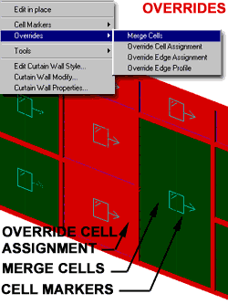 Illustrated to the right and left, I show a few simple Overrides
and how they were created using the Overrides tools from the object specific
pop-up menu ( select and right click). I also show that I prefer to work
with Cell Markers turned on. Illustrated to the right and left, I show a few simple Overrides
and how they were created using the Overrides tools from the object specific
pop-up menu ( select and right click). I also show that I prefer to work
with Cell Markers turned on.
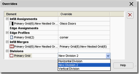
Once you have performed some simple Overrides, like Merging
and changing Cell Assignments, you will see these changes on the
Overrides tab, illustrated to the right. Some of these Overrides can not only be
removed here with the Remove button, but you can actually make other
changes to existing Overrides ( see drop-down menu for Cell Assignments, right ).
|
 |
| Curtain
Wall Properties - Roof/Floor Line tab
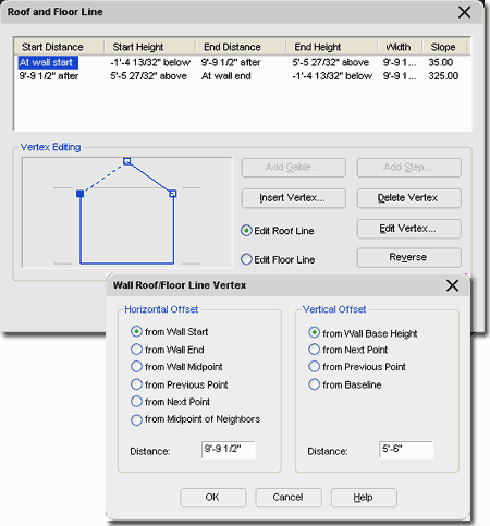
On the Roof/Floor Line tab of the Curtain Wall Properties
dialogue box, you will find the same set of tools and options offered on the same tab for
Walls. Though it appears, at first glance, that you could easily vary and slope your
Curtain Wall from this point, you may be surprised by the results. Frames, for
example, do not necessarily pop up where you want them. For this reason, I have not
used these options on Curtain Walls yet but that is not to say, you cannot find a good use
for these options.
See also discussion for Walls. |
 |
|
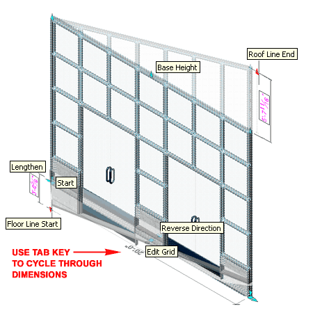
Curtain Wall Grip Points Curtain
Wall Objects have several Grip Points that work just like they do on
regular Wall Objects such as Lengthen, Start, End and Location. You
will also find that Curtain Walls have Base Height, Roof Line Start and End
and Floor Line Start and End Grips. The one Marker that is different from Walls is the
Edit Grid option that allows you to work on the Curtain Wall Layout live in
the Edit-in-Place mode. When you activate this Edit-in-Place mode, you
will find a whole new set of Grip Point that you can work with - see
discussion below for more on this subject. |
 |
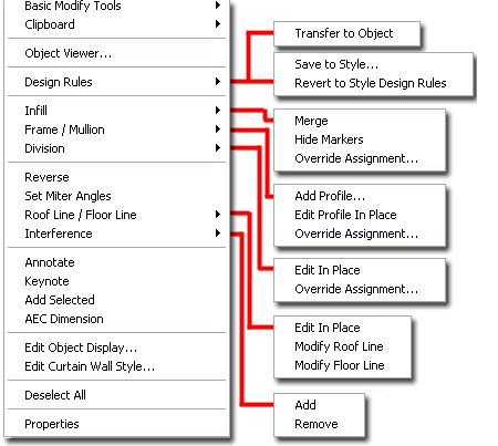
| Curtain
Walls - Editing via Object Specific Pop-up menu Illustrated to the right is the object specific pop-up menu for a selected
Curtain Wall. If you don't get the object specific pop-up menu when you select
objects, check the Options dialogue box ( Type "OP" ) and look
for two possible causes:
1) User Preferences tab, Windows
Standard Behavior, Shortcut Menus in Drawing Area should be checked
on on the Right-click customization dialogue box, make sure that Shortcut
Menu is checked for Edit Mode.
2) Selection tab,
Selection Modes, make sure Noun/Verb selection is checked.
When you need to Modify a Curtain Wall in place, you
actually have two choices. One approach has to do with using the Edit
in place option and the other simply works on the principle of Overrides.
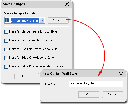
When you use Edit in place, you get more
tools, including the Overrides and the option to Discard changes or Save
changes... with a different Style name. This means that if you want the
best of all in place editing options, use the Edit in place option.
I find that working directly with the Overrides
often does the trick and thus I don't always go for the full set of Edit in place
options. I also tend to forget that I have activated the Edit in place option and
thus I keep getting the alert dialogue for Saving changes. If this stuff confuses
you, you should consider beginning your Editing in place work by skipping down to the Cell
Makers and Overrides topics below.
These tools are the best for visual minded designers who
prefer to work right on a 3D view of a Curtain Wall. They cannot, however, solve
every need and thus you will eventually have to go back and work with the Styles. I
do find that you can do quite a bit of work with these tools and often take a basic grid
and change it dramatically. |
 |
| Edit in place The
first time you select Edit in place off the object specific pop-up menu,
all you are doing it activating it; like an ON switch that is off by
default. To turn it OFF after activation, you have to select
either Discard Changes or Save changes... from the Edit
in place fly-out or cascading menu ( see illustration above, right ).
When Edit in place has been activated, the object specific
pop-up menu will change. The Edit in place menu option becomes a cascading menu with
two options: Discard changes and Save changes... You
should also find that the object specific pop-up menu gains two other editing options: Element
Definitions and Assignments.
Discard changes - this should be an
obvious option; it will allow you to go back to the original Curtain Wall Style before
Edit in place was activated.
Save changes... - this option allows you
to either save your changes back into the current style or into a new Curtain Wall Style.
|
 |
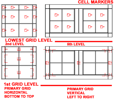
| Cell Markers Cell
Markers are used to help work with Overrides for Cells, Mullions
and Frames. Once on, they are physical objects that you can select
for such Override tasks as Merging ( in fact, oddly enough, you can even Snap to Cell
Markers ).
On the Cell Marker cascading menu off of
the object specific pop-up menu, you should find six options: Off, All
Visible, 1st Grid, 2nd Grid, 3rd Grid
and Other...
When you activate the All Visible Cell
Markers, you get all of the deepest level markers for all cells in a Curtain Wall Style.
This differs a bit from activating the deepest level markers within a Curtain Wall
that has Nested Grids - see illustration right with a 5th Level Grid. If All Visible
had been set on that Curtain Wall example, you would see the same markers plus markers for
the surrounding Cells, much like the example with a 2nd Level Grid level.
1st - 3rd and Other...
Grid Levels are for accessing specific levels of cells within a Curtain Wall Style.
1st Level will always provide you with an incomplete Cell Marker indicating the primary
Frame and its primary divisions. This can be used to work with Frame Overrides but
not Cell changes. The direction of the arrows indicate the direction of division
numbering ( as in horizontal, bottom to top ).
|
By using Other... you can access specific
Cell Levels nested deeply within a Curtain Wall Style and thereby avoid the possible
confusion cause by activating all cell markers.
My personal, "I don't have time for this",
approach is to just use the All Visible option and see what I get.
If there are too many cell markers to deal with I have solved that problem by Zooming in
and reducing Cell Marker
Size. |
| Cell Overrides With the
four Cell Override tools, you can achieve quite an impressive set of
modifications to a Curtain Wall Style. In this set, you have Merge Cells,
Cell Assignment, Edge Assignment and Edge
Profile.
Illustrated to the right are some of the basic things you
can do with Cell Overrides. The most powerful tool in the set is Cell Assignment Overrides
because this is how you can control what goes inside a Cell Division. You can assign
almost anything you want to a Cell; from simple Profiled shapes to something as complex as
another Curtain Wall.
Merge Cells - this option allows you to
select two cell markers at a time and remove any Mullions between them. These Cells
must be adjacent to each other.
Override Cell Assignment - this option
allows you to specify any Infill element currently listed in the Curtain
Wall Style ( this is done by specifying the index number on the command
line). To Add new ones, use the Curtain Wall Style dialogue box and add a New
Infill. Using the None option may produce some unexpected and
undesirable results; such as the removal of Frame and Mullion components.
Override Edge Assignment - this option
allows you to change or remove Frames or Mullions ( this
is done by specifying the index number on the command line). To
change a Mullion or Frame, use the Curtain Wall Style dialogue box and add a New Frame or
Mullion element. Using the None option may produce some unexpected
and undesirable results; such as complete full length removal of a mullion.
|
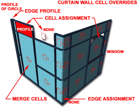 Override Edge Profile - this option allows
you to change a Frame or Mullion shape by either selecting a Close Polyline
or by selecting a Profile Definition ( this is done by selecting a closed
Polyline or by specifying a Profile name on the Profile Definitions dialogue box that you
get by hitting the Enter key). |
| Element Definitions
This set of options simply takes you directly to the
specific tabs on the current Curtain Wall Styles dialogue box that control these settings.
This option is only available when "Edit in Place" mode
has been activated. |
Divisions... number
of rows and columns and how they are spaced apart.
Infil... type of object that resides
between the rows and columns ( the cells ).
Frames... shape, form and dimensions
of perimeter frame.
Mullions... shape, form and
dimensions of internal divisionary elements ( between the cells). |
| Assignments
This set of options is based on the basic Overrides but
offers far more control over modifications and the number and location of these
modifications. Assignments are only available for Window Assemblies that have "Edit
in Place" active and thus assignments are not Overrides but actual changes
to the Style ( depending upon how you save the Edit in Place Assignments ). Be aware
that as with other forms of modifications to the Style, you will need to define the
options first in order to be able to select them with any of these tools. For
example, you cannot Add a Cell Assignment if it doesn't exist. You can, however,
create new New Element Definitions while working in "Edit in Place" mode - >
see comments for Element Definitions
above.
Add Cell Assignment - this option allows
you to change any or all Cell Infills to any other predefined Infill Definitions.
This is very similar to the Override Cell Assignment option. If you are confused by
the results of this tool, consider the original design of the Curtain Wall Style and its
Grid system. Adding a Cell Assignment within a Grid usually affects a full Column
but can appear to change only one Cell if the Grid only contains one Column of Cells.
Remove Cell Assignment - this option
allows you to remove any non-default Cell Assignments that may have been Added at another
time. Removal reverts to the default Cell Assignment.
Modify Cell Assignment - this option is
similar to the Add Cell Assignment but changes all instances of the Cell Assignment,
within the current Grid, to match the change selected. Add Cell Assignments
introduces new Assignments by Column or for All Cells while Modify will change all Cells
within the Grid that use the same Infill.
Add Edge Assignment - this option allows
you to change any single or all Frame/Mullion Edges within a specific Grid.
|
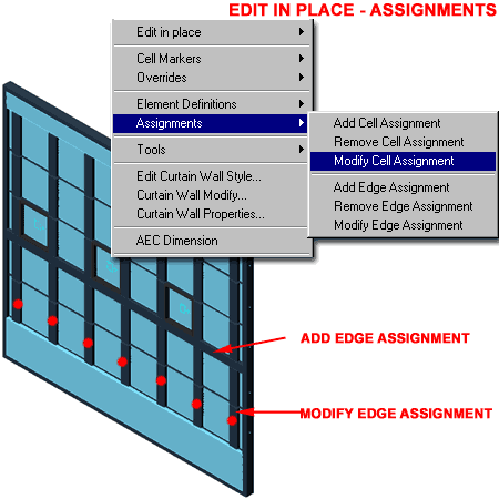
Remove Edge Assignment - this option
allows you to remove any non-default Frame or Cell Edge Assignments that may have been
Added at another time.
Modify Edge Assignment - this option is
similar to the Add Edge Assignment but changes all instances of the selected edge within
the specific Grid. |
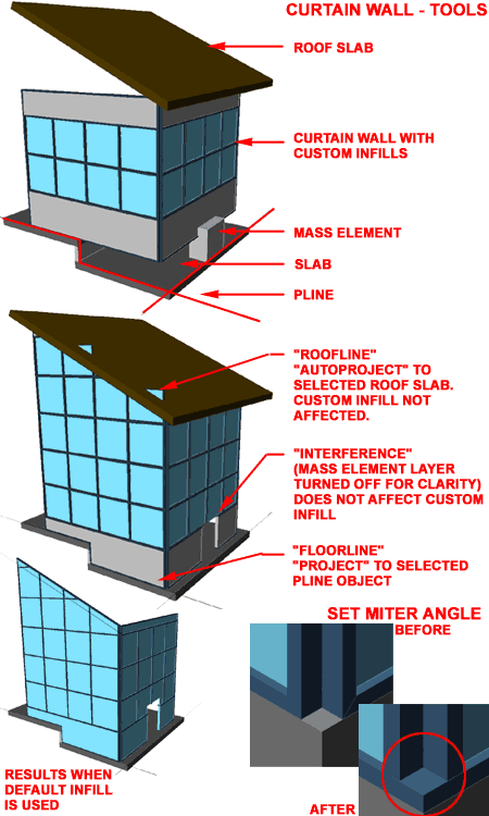
| Tools
To access the tools listed below, Select a
Curtain Wall, right-click on your mouse and look for the
Tools>
cascading menu option on the object-specific pop-up menu.
Reverse - this opinion flips a Curtain
Wall around like a mirror image but does not flip inside to outside. This is useful
when you have unique Offsets, for example, on one end but realize that you need them on
the other end instead.
Floor Line - this option is the same as
that for Wall objects and provides you with options for projecting your Curtain Wall down
to a Floor Slab, Space object or other object representing a base.
Roof Line - this option is the same as
that for Wall objects and provides you with options for projecting your Curtain Wall up to
a Ceiling in the form of a Slab, Ceiling Grid, Roof or other objects representing a top.
Interference - this option allows you to
add interference conditions much as you would with a Wall. In some cases Mass
Elements are used but you can use many of ADT's objects as Interference objects, even a
true Wall. Using this option will cut your Curtain Wall and wrap it around the
interfering object.
Set Miter Angles [GridAssemblySetMiterAngles] - this
option will automatically calculate the miter angle for Curtain Wall frames that meet at
an angle. Unfortunately this option only affects the top and bottom frames and not
the vertical frame elements.
|
|
| 6Curtain Wall Styles |
6-5 CURTAIN WALLS |
Style Manager - Curtain Walls
| Alt.Menu |
Design> Curtain
Walls> Curtain Wall Styles... |

|
 |
| Keyboard |
CurtainWallStyle |
| Mouse |
Select a
Curtain Wall Object, right-click and Select Edit Curtain Wall Style... |
| Links |
Loading Curtain Wall Styles -
for information on how to load ADT Curtain Wall Styles. |
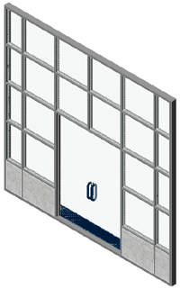 For Curtain Wall objects, you can use the Style
Manager to load, modify, delete and create new Curtain Wall Styles.
If you have already worked with Door/Window Assembly Styles, you will not
find this subject much different. For Curtain Wall objects, you can use the Style
Manager to load, modify, delete and create new Curtain Wall Styles.
If you have already worked with Door/Window Assembly Styles, you will not
find this subject much different.
Though you can easily create New Curtain Wall Styles
from Scratch using the New button, you may want to use the Copy/Paste
technique instead because it is far easier to Modify Settings of an existing Object Style
than it is to create one from Scratch. In some cases, you may even miss specific
settings that can come back to haunt you much farther down the road on a project - things
like Display Representations or Data for Schedules.
Illustrated to the right, I show the process of creating a New
Curtain Wall Style that I have Named "Custom Curtain Wall".
By double-clicking on this new style, you will invoke the Curtain
Wall Style Properties dialog box - as illustrated.
|
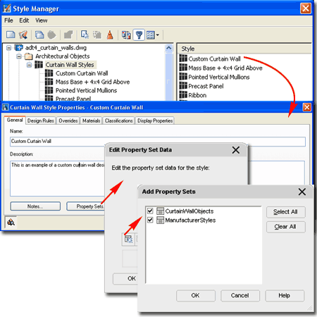 On the General Tab of the
Curtain Wall
Style Properties dialog, you will find a place to modify the Name,
add a Description, add Notes... and Property
Sets... If you intend to use the Schedule Tags and Schedule Objects in ADT,
you must use the Property Sets... button to Add the appropriate Property
Data. Data can be added for expanded
Schedules or additional Schedule Styles and you can even create new Data Sets but let's
put that topic off to Part 18 - Schedules.
Illustrated above, I show that
ADT comes with one example Property Set for CurtainWallObjects that
you may want to experiment with to see the type of data you can extract from
one of these Object Types. |
| Curtain
Wall Style Properties - Design Rules tab
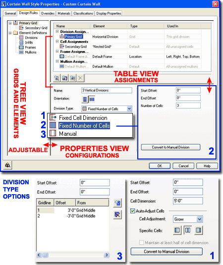
Illustrated to the right, I attempt to provide an understanding of
the Design Rules tab interface. On the left side
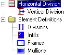
is a Tree View showing a Grid hierarchy, starting with a
Primary Grid and a folder containing the Element
Definitions that the Grids are comprised of. In the upper right
side, is a Table ( Column and Rows ) of the current Grid
Assignments. On the lower right side, is a Properties
or Settings view for the specific configurations of the currently selected Elements.
 When you select an
Assignment, such as Primary Grid, you should find numerous configuration
options in the Properties View area. The Primary Grid, for example, provides options
for unique Names, Orientation of Cells, Division
Types and corresponding options for these Division Types ( see 1, 2, and 3 ). When you select an
Assignment, such as Primary Grid, you should find numerous configuration
options in the Properties View area. The Primary Grid, for example, provides options
for unique Names, Orientation of Cells, Division
Types and corresponding options for these Division Types ( see 1, 2, and 3 ).
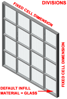
To create the simple Curtain
Wall Style
illustrated to the left, set the Horizontal and Vertical Divisions
to use a Fixed Cell Dimension, specify that dimension, set
desirable Widths and Depths for the Frames and
Mullions and then set desirable Materials.
By starting with a really simple
example such as this one, you can work with different values and settings to
see how they affect basic components. Once you start nesting layers of
Grids, it gets a lot more difficult to visualize in your mind what you need
to change in order to get desirable results.
|
See
Section 8 - Curtain Wall
Styles - Design Rules for a more in-depth discussion of this
subject. |
| Curtain
Wall Style Properties - Overrides tab
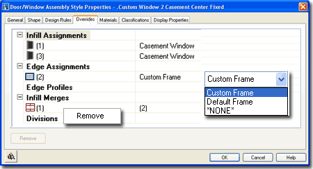
The Overrides tab will not offer anything
other than the Override categories unless you have actually performed Override tasks and
Saved them to the current Curtain Wall Style.
Once you have made Override changes and used the Save
Changes dialog box via the Edit in Place object-specific pop-up menu,
then you will see those changes reflected here as illustrated to the right. Not only
can you make more changes to overrides here, you can Remove them.
To find out about creating overrides, read
Section
5 - Modifying Curtain Walls |
 |
|
Curtain Wall Style Properties -
Materials tab
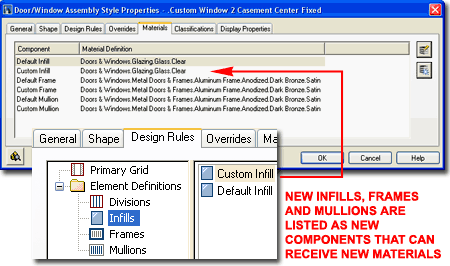
Illustrated to the right I show that all
Curtain Wall Styles offer three Default Components under the
Material tab: Default Infill, Default Frame and Default Mullion.
If you create New Infill, Frame and/or Mullion Element Definitions they will
automatically be listed as new Components under the Materials tab.
This means that should you need unique Material characteristics such as
different Frame Materials for example, you can define New Frames for each
side of the Curtain Wall. You can also use this feature to create Infills
that are Glazed, Metal, Wood or any other Material.
Since Materials can also be used to control
line properties, you may want to use an existing Curtain Wall Style as the
source for any new ones you create. |
 |
|
Curtain Wall Style Properties -
Classifications tab
Curtain Wall Styles have a
Classifications tab that is identical to that for most Object Styles.
See discussion under Doors and Windows for more on this subject. |
|
|
Curtain
Wall Style Properties - Display Properties tab
The Display Properties tab
of the Curtain Wall Style Properties dialog box, illustrated right, provides access
to a set of Display Representations similar to those found for Walls. Keep in mind that in addition to the Display Properties for
the Curtain Wall you can also control the Display Properties of the Objects you
use as Infills by working with their own Style Properties. In other
words, the Curtain Wall only provides control over its short list of
Display Components ( Infills, Frames and Mullions ) while Doors and Windows or other Inserted Objects are managed by their own Display Properties.
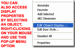 Illustrated
to the left, is another way to access the Display Properties tab; select
the specific object, right click on your mouse
to invoke the object-specific pop-up menu and select Edit Object Display... Just
be aware that when you use this approach, you can actually set an Object Override as
opposed to a Style Override. Object Overrides can be extremely useful because they
allow you to add things like Sills or Thresholds to any object within a Style Family but
they can also be problematic because they lock you out from more centralized, Style level,
controls. Illustrated
to the left, is another way to access the Display Properties tab; select
the specific object, right click on your mouse
to invoke the object-specific pop-up menu and select Edit Object Display... Just
be aware that when you use this approach, you can actually set an Object Override as
opposed to a Style Override. Object Overrides can be extremely useful because they
allow you to add things like Sills or Thresholds to any object within a Style Family but
they can also be problematic because they lock you out from more centralized, Style level,
controls.
|
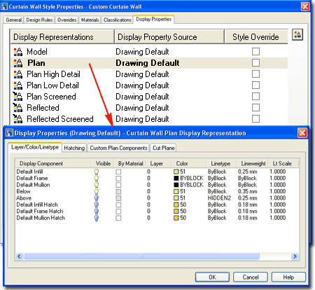 In Plan view, you have Layer controls for Infill,
Frame and Mullion. You can also have these
components filled with User Specified Hatch patterns controlled on the Hatch
tab. The Custom Plan Components tab offers the ability to add
custom features to the "generic" Assembly. The Cut Plane
tab allows you to re-define where you want the cut made on your Door/Window Assemblies.
This can be a valuable option if you introduce Interferences within your
Door/Window Assemblies
and wish to have those displayed or not displayed in plan view. |
| 7Curtain
Walls -
Display Properties |
7-5 CURTAIN WALLS |
|
Curtain Wall Display Property Overview
The Display Properties of Curtain Walls are actually
quite simple since there are basically only three components to work with:
Frames, Mullions and Infills. Curtain Walls can
complete in themselves or you can think of them as the framework for
inserting all sorts of other Objects. When using other Objects, such
as Doors or Windows, as Infills those Objects must be controlled by their
respective Display Properties.
Below I will discuss some of the basic
concepts of working with Curtain Wall Styles and their Display Properties
and then elaborate further for those who really need to dig in and create
highly custom Styles.
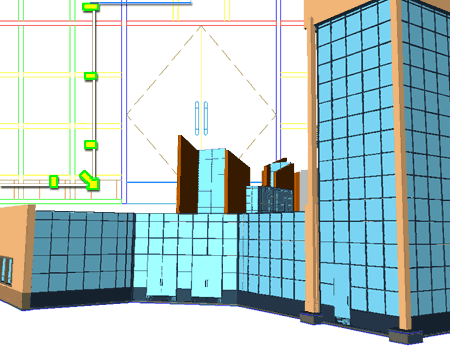
Illustrated to the right I show three
different Views an example Curtain Wall I used on a project for a college
campus building.
In Plan View I show that I I have custom Corner Frames to
more accurately represent how the Curtain Wall will be constructed. In
Elevation View I show, colored, the heirarchy of Mullions used to
achieve a flexible Style design. In Model View I show a simple
base panel and the insertion of Doors. |
 |
|
Curtain Walls in Plan
Depending on how many design features you
have put into your custom Curtain Wall Styles, the task of producing the
desired Plan View display could proved to be nearly as difficult as
creating the Style to begin with. If you span multiple floor levels
with one Curtain Wall Object, you may find that one Plan Display is only
good for one floor.
Illustrated to the right I show a simple
Curtain Wall Object for a single floor level with entry doors inserted as
"Infill" and glazed panels in all of the adjacent "Cells". Since
Plan, Plan High Detail and Plan Low Detail
all offer the same set of Display Components, it will not matter for
this discussion which one you are working with. In the example to the
right I do not show the Below Display Component because it would
prevent us from seeing the Above Display Component. Generally,
I do not use the Hatch Patterns in my Curtain Walls but you may want to us
them for Presentation drawings.
Notice that though I have Doors as an Infill,
there is no control for the Display of the Door Style within the Curtain
Wall Display Components list. For custom Objects, you must work
directly with their own Style Properties.
As you can see, the list of Display
Components and what they control is fairly simple to comprehend; it's the
Cutting Plane subject that is the real key to controlling what you see
in Plan. |
 |
|
Curtain Walls Above
or Below the Cutting Plane
Generally, a
Curtain Wall Object stands free much like a Wall Object and thus defers its
default Cut Plane Height to the current Display Configuration ( just like a
Wall ). The problem with this default setting is that a Curtain Wall
usually has a lot more internal detail than a Wall and thus you are likely
to want to set a more specific point through which you want the Cut Plane
Height. In addition to this, the default Above and Below Cut Plane
Heights typically reach well beyond the elevation heights of a Curtain Wall
and thus prevent you from capturing and Above or Below linework. You
may have notice this when turning on the Above and/or Below Display
Components in Plan only discover no change at all.
Illustrated to the right I show three
different Plan Display results based on three different Cut Plane scenarios:
the Default, a Custom Height and a Custom Height with Custom Above and Below
Cut Plane Heights as illustrated on the Cut Plane tab, left. Of course
the design of your custom Curtain Wall Style will affect the results and you
may be lucky enough to use the Default Cut Plane Height as controlled by the
current Display Configuration. If you want to take advantage of the
Above and/or Below linework, you will need to set Manual Above and Below Cut
Plane Heights that run through the Components that you want to Display in
Plan. |
 |
|
Curtain Walls Spanning Multiple Floors (Levels) - Elevation
From a designer's point of view, creating one
Curtain Wall Object that is used for many floors is far easier to manage
than replicating work on each floor as separate Curtain Wall Objects.
From the view on a Construction Document, the important thing is that
the correct linework is illustrated for the Curtain Wall at each floor.
Attempting to get both is not always easy and at times I have used one
Curtain Wall Object as a master for Elevations, Sections and so on while
using special replicas on each floor drawing that produces the desired
linework I must have on my CD's. This may seem ridiculous but it may
also be necessary given the limitations of Cut Plane controls on Curtain
Walls when spanning floors.
Assuming you are using one Curtain Wall
Object and Xref'ing it into multiple floor plan drawing files, the worst setting you can
tinker with is the "Override Display
Configuration Cut Plane" because that will fix whatever "Cut Plane
Height" you set in the source file for all of the other files you
Xref the Curtain Wall into.
Unless you take the time to create unique
Display Representations and unique Display Configurations that can then be
used as Display Overrides on Xref'd Curtain Wall Objects, you have to work
with the current
Display
Configuration Cut Plane Ranges and Manual Above and Below Cut
Plane Heights. Illustrated to the
right I show an example Curtain Wall Object in Elevation and how two Manual
Cut Plane Height Settings are read relative to the 2nd Floor. Keep in
mind that when you use the Project Navigator tool, it automatically drops
the Curtain Wall down relative to the Z-axis establishing a new Z=0 Cut
Plane point ( base of 2nd Floor Z-axis = 0). If you work with Xref's
manually, make sure to Move your Curtain Wall down in the Z-axis to the
appropriate Floor Line position.
The current Display Configuration,
illustrated lower right, affects how your Curtain Wall is displayed relative
to Z=0. This is an absolute World Coordinate System value that cannot
be changed. You can, however, move the Object relative to this value
in order to change how it is perceived or presented but that's yet another
story. You may find, as illustrated to the right, that the default
Above and Below Cut Plane Ranges exceed what you want to display. You
can change them but be aware that these ranges are Global for most Objects
in the current drawing so setting the Display Below Range ( labeled as "C")
higher than zero may not be such a great idea. These Range values can
be used to exclude or include Manual Cut Plane values set on Curtain Wall
Objects - see discussion directly below. |
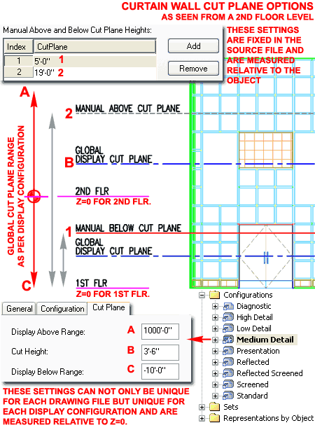
In my example, I show that I have set two Manual
Cut Plane Heights on the Curtain Wall Object itself. This is achieved
by working through the Display Representation, such as Plan. These
values are static and measured from the zero base of the Curtain Wall
Object. This means that a Cut Plane Below Value for the 2nd Floor
Point of View may also be the Above Cut Plane Value from the 1st Floor Point
of View. If you follow that logic, conflicts can occur where you have
just what you want on one floor but not on another and there may be little
that you can do. If you are facing such a dilemma, consider assigning
the Above and Below linework to fixed Layer Names so you can use yet another
form of control in the Xref'd file. |
|
Curtain Walls Spanning Multiple Floors (Levels) - Plan
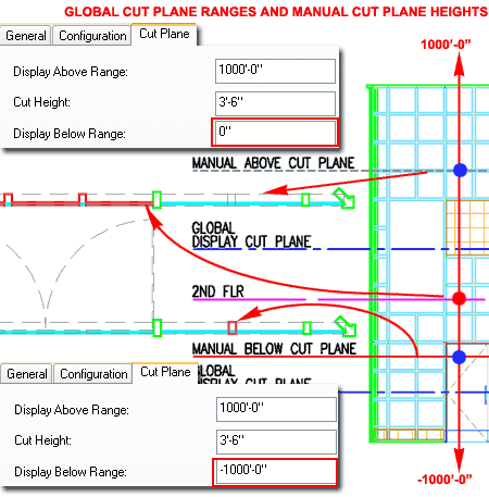
Illustrated to the right I show how the "Display
Below Range" of the current Display Configuration affects how the
Manual Below Cut Plane value is displayed for a 2nd Floor Level Plan
View of the same multi-level Curtain Wall example discussed above.
By setting the "Display Below Range" value to
zero, the only components that are displayed as Below the Cut Plane are
those that fall between the Cut Height and the Floor ( assuming it is at
Z=0).
By setting the "Display Below Range" value to
a huge negative number ( essentially negative infinity), the Manual Below
Cut Plane value set on the Curtain Wall Object is now used to determine the
components that are to be illustrated as Below the Cut Plane.
Obviously a similar result can be achieved
for the "Display Above Range".
Note:
To include such items as Doors or Windows Anchored as Infills in Curtain
Walls, you will need to change their
Display
Representations to display Components that are Above and/or Below the Cut
Plane. Such changes must be done on the Object or Object Style
in the source Curtain Wall file. |
 |
| Display
Properties - Custom Components
Each of the Display Representations for
Curtain Wall Styles offer the option to Add Custom Components by
means of Attaching a Block. Only the Model Display
Representation Properties dialog uses the "Other" tab for this feature while
all other Display Representations use the "Custom Plan Components" tab
illustrated to the right.
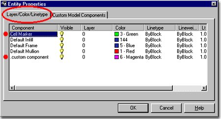
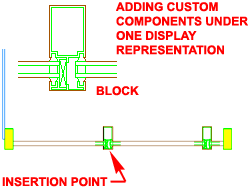
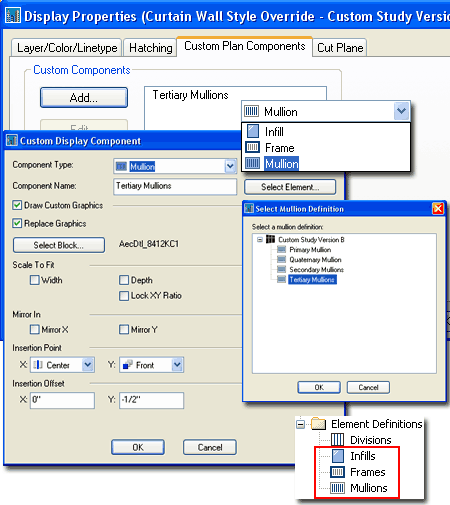
Illustrated to the right I show how I have used
the "Custom Plan Components" tab on the Display Properties dialog
of the "Plan" Display Representation to Add... a Custom Block of a Mullion
Section created earlier with the Detail Manager. By defining different
Mullions for different parts of my Curtain Wall example, I was able to
Select a specific Mullion type on the "Select Mullion Definition" dialog (
Select Element... button ).
 Draw
Custom Graphics - use this checkbox to allow for the insertion of a
Block in the position of the Component Name. If you elect not to use
this option, you will not be able to Select a Block but you should find that
you will now have a new Display Component Layer - see comments below under
"Other tab". Draw
Custom Graphics - use this checkbox to allow for the insertion of a
Block in the position of the Component Name. If you elect not to use
this option, you will not be able to Select a Block but you should find that
you will now have a new Display Component Layer - see comments below under
"Other tab".
Replace Graphics - use this checkbox to
have the Block replace the Component's Graphical representation; i.e.,
substitute the Block for the default linework.
Select Block... - use this button to
select any Block in your current drawing.
Scale, Mirror and Insertion
options can be used to control how the Block is positioned relative to the
Component. In some cases you may need to alter the block in order to
get better results. Since there is no option to Rotate, you may find
that you will need to get the right rotation before making your Block. |
 |
|
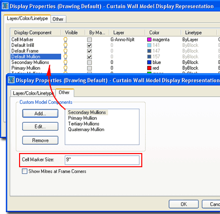
Display
Properties - Other tab
When you Add Custom Components for Plan or Model
Display Representations, you also receive new Display Component Layers with
names to match the Selected Component Name. Be aware, however, that
these Custom Display Component Layers cannot be set to "By
Material" and are thus relegated to basic Color and Linetype settings.
Illustrated to the right I show the Display
Properties dialog for the Model Display Representation. Notice that
the Other tab offers the option to change the "Cell Marker Size" which is
that little rectangle you see over Cells when editing in place. This
Cell Marker is incredible useful when you
need to Select Cells for such tasks as Merging or changing the Infill. |
 |
|
8Curtain
Wall Styles - Design Rules - Basics |
8-5 CURTAIN WALLS |
Design
Rules - Basics
| Alt.Menu |
Design> Curtain
Walls> Curtain Wall Styles... |

|
 |
| Keyboard |
CurtainWallStyle |
| Mouse |
Select a
Curtain Wall Object, right-click and Select Edit Curtain Wall Style... |
| Links |
Style Manager - Curtain Walls
- for information about the General and Default tabs. |
For some, the process of mastering the
Curtain Wall Style can be daunting while others seem to grasp the layering
or "Nesting"
of Divisions and Infills in seconds. I happen to be of the former
category because I think more visually than mathematically. In the
steps below I will start with a simple grid-based Curtain Wall Style and go
on to more sophisticated options in Part 9.
In the illustration to the right I show that
I have created a New Curtain Wall Style from Scratch that I
named "Custom Study Version A". Skipping
over to the Design Rules tab, we can begin the discussion right here.
Since most Curtain Wall Styles involve
horizontal and vertical Frames and/or 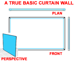 Mullions you will find that when you
create a New Curtain Wall Style, there will be two Grids but if you don't
want to use a second Grid, you can set the Cell Assignments to "Default
Infill" or define a custom Infill. For a basic Curtain Wall Style,
do not set the first Cell Assignment to *NONE* because you will
not have a Curtain Wall Object if you do this. Notice that when remove
the *Nested Grid* option as a Cell Assignment, you will find that the
"New Nested Grid" category will drop out under the "Primary Grid"
(Left side Tree View Pane) leaving
you with a very simple and basic Curtain
Wall Style. Mullions you will find that when you
create a New Curtain Wall Style, there will be two Grids but if you don't
want to use a second Grid, you can set the Cell Assignments to "Default
Infill" or define a custom Infill. For a basic Curtain Wall Style,
do not set the first Cell Assignment to *NONE* because you will
not have a Curtain Wall Object if you do this. Notice that when remove
the *Nested Grid* option as a Cell Assignment, you will find that the
"New Nested Grid" category will drop out under the "Primary Grid"
(Left side Tree View Pane) leaving
you with a very simple and basic Curtain
Wall Style.
|
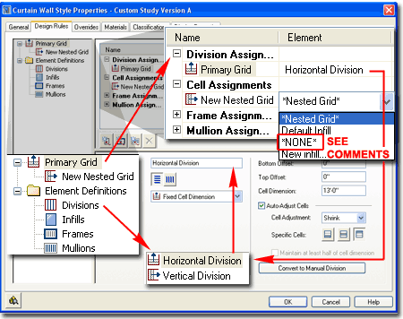
By highlighting the Primary Grid in the left
pane (Tree View), we can see how the primary Curtain Wall Grid is
configured. In the right pane (Table View), you can see that the
Primary Grid uses a "Horizontal Division" and this Element is stored under
the Element Divisions folder in the left pane as "Divisions". When you
Select the Divisions category, you will see all the same settings that you
are likely to see when you Select the Primary Grid category. This
means that you can often make changes to Elements without actually going to
the Element Definitions Folder. |
| Design
Rules - Dividing a Cell
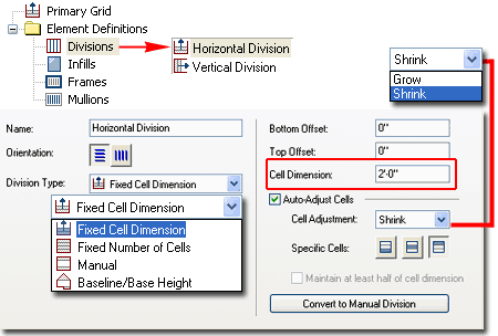
 After
you have created your New Curtain Wall Style, you are likely to want to
define the grid layout first. By going to the Divisions category under
Element Definitions in the Tree View of the Curtain Wall Style Manager, you
can modify any default Divisions, Remove, Rename or Add new ones. After
you have created your New Curtain Wall Style, you are likely to want to
define the grid layout first. By going to the Divisions category under
Element Definitions in the Tree View of the Curtain Wall Style Manager, you
can modify any default Divisions, Remove, Rename or Add new ones.
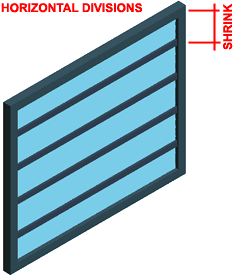
Illustrated to the right I show that I have
selected the default "Horizontal Division" and changed the Cell
Dimension to 2'-0" [610mm]. Though there are numerous other
options to play with here, let's not worry too much about them until later
so just confirm that you have an Orientation set to horizontal lines,
a Division Type set to "Fixed Cell Dimension" and Cell Adjustment
set to "Shrink". |
 |
| Design
Rules - Division Assignment - Orientation
Creating a Curtain Wall Style with Horizontal
Divisions is fairly easy but getting to the next step of adding Vertical
Divisions may prove to be just a bit more difficult.
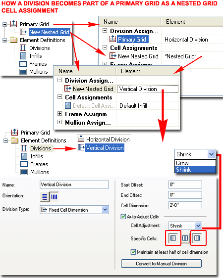
In the illustration to the right I show what
it takes for a 2nd Division to be a part of the Primary Grid. The
fundamental concept to comprehend here is that one Grid can only hold
one
Division Definition and thus cannot be both Horizontal and Vertical
simultaneously. In order to get both a Horizontal and Vertical
Division (as a true grid), you set one Grid to hold the Horizontal Divisions
and layer or "Nest" another over it to hold the Vertical Divisions.
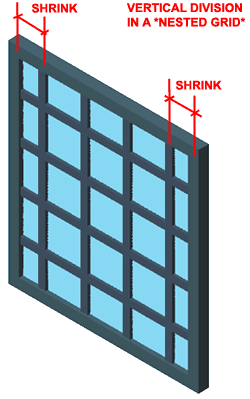 As
with the Horizontal Division discussed above, I show that I have defined a
rather simple Vertical Division to the right. Notice that the
Orientation button is set to vertical lines, that I am using
Fixed Cell Dimensions again set to 2'-0" [610mm] but that I have decided to
Shrink both
Ends so my Curtain Wall will always remain symmetrical. As
with the Horizontal Division discussed above, I show that I have defined a
rather simple Vertical Division to the right. Notice that the
Orientation button is set to vertical lines, that I am using
Fixed Cell Dimensions again set to 2'-0" [610mm] but that I have decided to
Shrink both
Ends so my Curtain Wall will always remain symmetrical.
To make any new Division actually produce
results in your Curtain Wall Style, you must use it as part of a Division
Assignment. In order to Add new Division Assignments, you have to Add
the *Nested Grid* Element as part of the Parent Grid's Cell Assignments
( in this case, the Primary Grid).
In other words, you are declaring that for a particular Grid's Cell
Assignment you want to set another Grid that has its own Divisions.
Overview of Options and Settings
The Name field is used by you to keep
track of these potentially confusing nested grids but you can name them just about
anything, like "1".
The two Orientation buttons for the Grid
Assignments ( Primary, Secondary, Tertiary and so on ) can be used at any point
in the Curtain Wall design process and simply create horizontal or vertical Cells ( these
are expressed as Mullions by default ).
Division Type can also be changed at any
point in the design process. There are four options for the Primary Grid and four
for all other Grids that follow.
| Primary Grid |
| Fixed Cell Dimension
- provides you with value fields for Start Offset, End Offset, Cell Dimension and the
option to AutoAdjust Cells. The basic concept is that you specify the
center-to-center dimensions with Offset adjustments at the ends where your Frame is
probably wider than the mullions; thus, to keep everything even, you will need to offset
inward to make your cells equall all the way across your Curtain Wall. The AutoAdjust options can be used to Shrink or Grow Cells to the Left, Bottom, Middle, Top or
Right ( depending on Cell direction ) when a Curtain Wall is drawn longer, taller, shorter
or anyway that is less than the optimum amount. Fixed Number of Cells - the easiest to deal with
because it just divides the Cell equally. You can use the Start and End Offset
values to adjust and compensate for corner conditions where your Frame may be wider than
the mullions; i.e., where center-to-center values need adjustment. |
|
|
Manual
- this is a more complex system for managing the center-to-center distance of your Cells,
but by using this option you can specify exactly where you want your Mullions relative to
Left, Top, Middle, Bottom, Right ( depending on Cell direction ). You can even add
Offsets to individual centerlines with this option.
Baseline/Base height - available only for
Horizontal Cell Divisions. This is another easy option because it only offers you
two choices: to add a Cell Division up from the bottom ( Baseline Offset
) or to add a Cell Division down from the top ( Base Height Offset
).
For the Base Height Offset, you can use a negative number to bring a division down
into the main Frame area. The real purpose of this option is for irregular curtain wall
profiles that have things like gables or steps. I
might get into more on this later but the Help menu in ADT covers this fairly well.Polyline - available only for Vertical
Cell Divisions. This option is an interesting one because it reads the vertex
points within a contiguous polyline used to generate a Curtain Wall and places a
Mullion at those vertex points. If you want a fast solution to a very irregular set
of vertical cells, just draw a contiguous polyline with points at every interval where you
want a new cell. |
| Secondary,
Tertiary, Quaternary, etc., Grid |
| Fixed Cell Dimension - see
comments above. Fixed Number of Cells
- see comments above.
Manual - see comments above.
Baseline/Base height - see comments above.
Polyline - see comments above. |
|
|
Design Rules - Infills
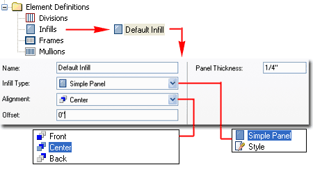
Under the Infills category, you will find a
Default Infill
that you can think of as Glazing, Solid Panels or any other default material
for each of the Cells in your
 Curtain
Wall Grid. Illustrated to the right I show that I have simply changed
the Panel Thickness
to something more appropriate for glass. Later I will discuss how to
mix glass and solid panels for more custom Curtain Wall Styles. Curtain
Wall Grid. Illustrated to the right I show that I have simply changed
the Panel Thickness
to something more appropriate for glass. Later I will discuss how to
mix glass and solid panels for more custom Curtain Wall Styles.
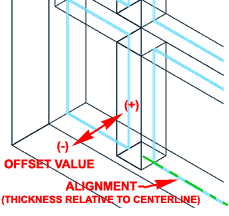
Notice that
you can work with the three Alignment
options ( Front, Center and Back) to describe how you want the Infill to be
centered; i.e. relative to the Front of the Panel based on its Thickness, to
its Center or to its Back. In addition to this Alignment you can use
the Offset to
push the Infill in the Negative or Positive direction ( even right out of
the Grid ).
|
 |
|
Design Rules - Frames and Mullions
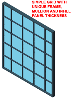 For
the last part of working with the Desing Rules tab of your custom Curtain
Wall Style, you will probably want to set the Frame
and Mullion
dimensions.
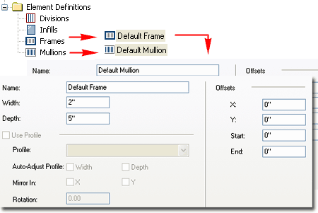
Illustrated to the right I show that the Property Settings for Frames and
Mullions are identical. For
the last part of working with the Desing Rules tab of your custom Curtain
Wall Style, you will probably want to set the Frame
and Mullion
dimensions.
Illustrated to the right I show that the Property Settings for Frames and
Mullions are identical.
For my example
I set the Frame Width and Depth to values a bit greater than those of the
Mullions. Later I will discuss how you can work with individual Frame
and Mullions to create such things as custom shapes and dimensions for Sills
|
 |
|
9Curtain
Wall Styles - Design Rules - Detailed |
9-5 CURTAIN WALLS |
Design Rules -
Primary Grid Division
| Download |
Part X - Appendix - to download
this example Curtain Wall Style and see the completed results. |
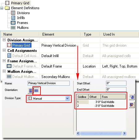
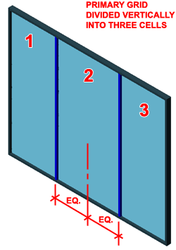 When
creating more complex Curtain Wall Grid Configurations, you have to start
from the outside and work your way inward towards the various Cell
Assignments. Illustrated to the right I show how I have divided a
Primary Grid into Three Vertical Cells. To allow the
Right and Left Cells variable lengths, I show that I have set a Manual
Division Type with a positive and negative distance
from the Grid Middle to my Vertical Mullions. Using this technique
will create a fixed center allowing you to Stretch the Curtain Wall out to
the Right or Left. This Center or Middle Division will always remain
centered so as you Stretch the Grid, the center will automatically readjust.
At times, you may find that you want a set distance from one End instead. When
creating more complex Curtain Wall Grid Configurations, you have to start
from the outside and work your way inward towards the various Cell
Assignments. Illustrated to the right I show how I have divided a
Primary Grid into Three Vertical Cells. To allow the
Right and Left Cells variable lengths, I show that I have set a Manual
Division Type with a positive and negative distance
from the Grid Middle to my Vertical Mullions. Using this technique
will create a fixed center allowing you to Stretch the Curtain Wall out to
the Right or Left. This Center or Middle Division will always remain
centered so as you Stretch the Grid, the center will automatically readjust.
At times, you may find that you want a set distance from one End instead.
Illustrated above left, I show that this work
provides three individual Cells that can now receive a common or individual
Cell Assignments. |
 |
|
Design Rules - "Nest Grid" Cell Assignment
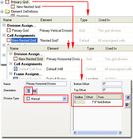
From the Primary Grid, we can work with the
three new Cell Divisions created above by Assigning a new *Nested Grid*
to one or all three. Illustrated to the right I show that I have
replaced the "Default Infill" Cell Assignment with the *Nested Grid* option.
The default name for this new grid is "New Nested Grid" but in most cases,
default Curtain Wall Styles will have this 2nd Grid named as "Secondary
Grid".
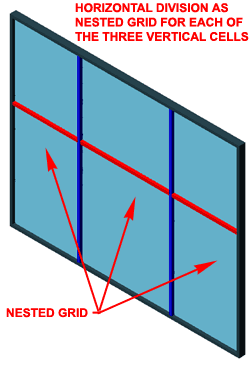 For
this new Cell Division I show that I have a Horizontal Orientation
set to Manual Division Type with a specific dimension measured
from the Bottom. Using this technique, you can define a head frame or
mullion for such things as Doors and Windows. For
this new Cell Division I show that I have a Horizontal Orientation
set to Manual Division Type with a specific dimension measured
from the Bottom. Using this technique, you can define a head frame or
mullion for such things as Doors and Windows.
Illustrated to the left I show that because I
only have one Cell Assignment for my Primary Grid, that Assignment will
automatically be applied to each of the three Cells defined by the Primary
Grid Division. |
 |
|
Design Rules - Locating Multiple Nested Grids
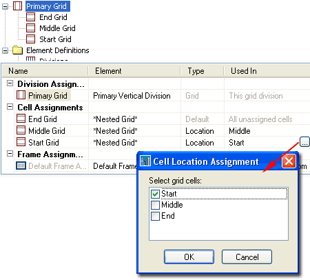
By adding more Cell Assignments for the Primary
Grid, as illustrated to the right, you should find the option to use the
Index or Location dialog to specify the position of each
Cell Assignment. There will always be one that remains set to "All
unassigned cells".
Illustrated to the right I show that I have
added a total of three Cell Assignments to my Primary Grid and set each to a
specific Location. I have also Renamed the Cell Assignments to match
the Location for easier reading.
Note:
If the Primary Grid had been Divided Horizontally, instead of Vertically,
the Location dialog would have offered Top, Middle and Bottom as positions. By using the
Index option, you can type in the
Index number(s) for the Cell positions; e.g., "1" might be the Bottom, "2"
would be the next one up from the Bottom and "2,5" would be the second
and the fifth. |
 |
|
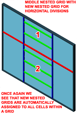
Design Rules - Nested Grid inside a Nested Grid
In the step outlined above I illustrated how you
can add multiple Cell Assignments as Nested Grids but those Nested Grids
will use the same Division by default so more work will be required to see
the results of this work.
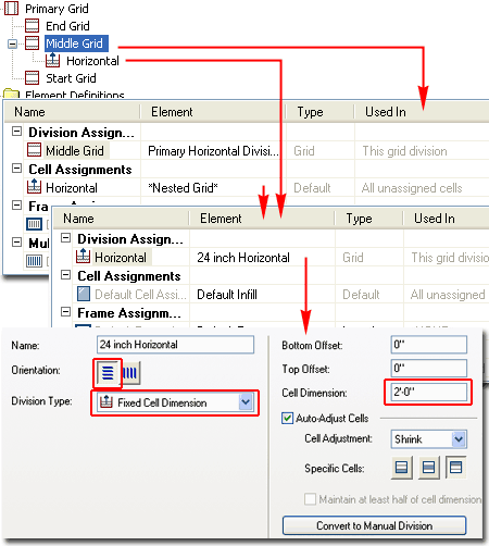
 Illustrated
to the left I show how I have Selected one of the Three Cell Assignments as
a sub-grid in the Tree View Pane. For this sub-grid I have left the
Division as set but in order to introduce more Mullions, I added yet another
Nested Grid as a Cell Assignment. In essence this is a sub-sub-grid
that shows up under the parent sub-grid. For this sub-sub grid I show
that I have created a New Division Assignment that I named at "24 inch
Horizontal" to make it easy to read later. Illustrated
to the left I show how I have Selected one of the Three Cell Assignments as
a sub-grid in the Tree View Pane. For this sub-grid I have left the
Division as set but in order to introduce more Mullions, I added yet another
Nested Grid as a Cell Assignment. In essence this is a sub-sub-grid
that shows up under the parent sub-grid. For this sub-sub grid I show
that I have created a New Division Assignment that I named at "24 inch
Horizontal" to make it easy to read later.
For the configuration of this Horizontal
Division, I set the Orientation to Horizontal, used the Fixed Cell Dimension
to set a Cell Dimension of 24" [610mm]. Because I expect to use this
Division for the top of this grid and not the bottom, I have set the Shrink
to Top only. |
 |
|
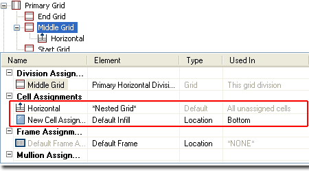
Design Rules - Locating a Nested Grid inside a Nested Grid
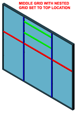 In
order to force the new "24 inch Horizontal" Division to only affect the top
portion of my grid, I show that I have Select the parent sub-grid and added
a New Cell Assignment that I set to "Default Infill". By adding this
New Cell Assignment, I can use the Location dialog as discussed earlier, to
force the sub-sub grid to the top as illustrated to the left. In
order to force the new "24 inch Horizontal" Division to only affect the top
portion of my grid, I show that I have Select the parent sub-grid and added
a New Cell Assignment that I set to "Default Infill". By adding this
New Cell Assignment, I can use the Location dialog as discussed earlier, to
force the sub-sub grid to the top as illustrated to the left.
|
 |
|
Design Rules - Multiple Nested Grids
In order to make a true grid that used both
Horizontal and Vertical Mullions, I show that I have to add yet another
Nested Grid because one grid can only define one Division.
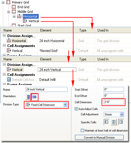
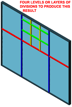 Illustrated
to the right I show that I have Selected the sub-sub Grid created in the
last step and added a Nested Grid as a Cell Assignment to create a
sub-sub-sub Grid. For this deepest Grid, I show that I have added a
New Division Assignment that I have named "24 inch Vertical" and configured
as having a Vertical Orientation, Fixed Cell Dimension of 2'-0" with Shrink
set to Left and Right Illustrated
to the right I show that I have Selected the sub-sub Grid created in the
last step and added a Nested Grid as a Cell Assignment to create a
sub-sub-sub Grid. For this deepest Grid, I show that I have added a
New Division Assignment that I have named "24 inch Vertical" and configured
as having a Vertical Orientation, Fixed Cell Dimension of 2'-0" with Shrink
set to Left and Right
|
 |
|
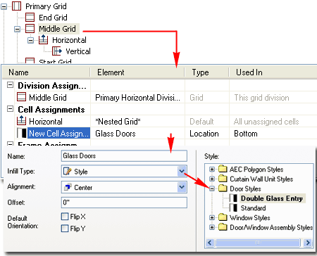
Design Rules - Custom Styles as Cell Assignments
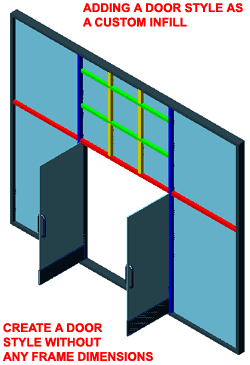 For
the Bottom Cell of the Middle Grid I show that you can use the Cell
Assignments to add things like Door and Window Styles. Notice that
this is also how you add Curtain Wall Unit Styles for even more complex
configurations. For
the Bottom Cell of the Middle Grid I show that you can use the Cell
Assignments to add things like Door and Window Styles. Notice that
this is also how you add Curtain Wall Unit Styles for even more complex
configurations.
Illustrated to the right I show that I have
Added a new Cell Assignment to the Parent Middle Grid and set the Infill
Type to Style to allow me to Select any of my current Door Styles. The
Door Style that I have Selected and show to the left was custom Door Style
created with no Frame so it will appear to hinge off the side Mullions. |
 |
|
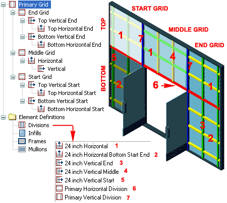
Design Rules - Completing a custom Grid System
After you comprehend the steps taken above you
should find that there is little more than extremely tedious redundancy for
expanding those steps to a larger design solution.
In the illustration to the right I show how I
repeated similar steps used to create the Grid above the Doors to the create
Grids for the Top Start ( Lower Left ), Bottom Start ( Lower Left ), Top End
( Upper Right) and Bottom End ( Lower Right ). You might argue that I
have overdone the configuration but that all depends on the results you
expect and how flexible you want the Style to be. I created a Lower
Left and Right Grid Division in order to allow for Horizontal Mullions that
can start at a unique height above the floor without affecting the entire
Left Side; i.e., I isolated it to a Cell below the Door Head Mullion.
You should also notice that I have a lot of
redundancy but that was necessary to allow for Vertical Mullions to Shrink
to the Right on the Right and to the Left on the Left |
 |
|
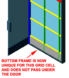
Design Rules - Controlling Frames
Many have complained to me about how the Bottom Frame in Curtain Walls
passes under Doors or Openings so here is an example of how you can expand
on the work above to control this result.
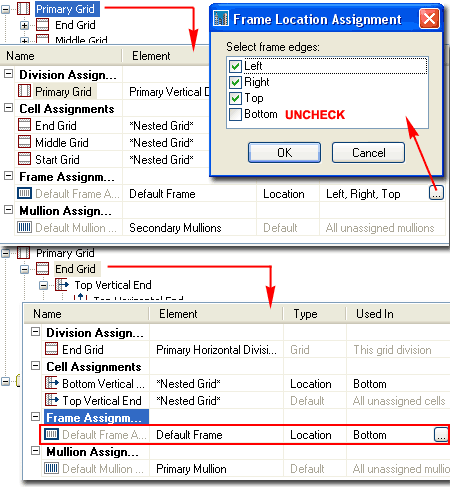
 Illustrated
to the right I show how I have returned to the Primary Grid by
Selecting it in the Tree View Pane. Under the Frame Assignments
category in the Table View I show that I have picked in the "Used In"
column of the Frame row to activate the Frame Location Assignment dialog
where I have unchecked the Bottom button. This will
remove any Frame reference for the bottom of the Curtain Wall Style. Illustrated
to the right I show how I have returned to the Primary Grid by
Selecting it in the Tree View Pane. Under the Frame Assignments
category in the Table View I show that I have picked in the "Used In"
column of the Frame row to activate the Frame Location Assignment dialog
where I have unchecked the Bottom button. This will
remove any Frame reference for the bottom of the Curtain Wall Style.
Because of how this example Curtain Wall
Style was Divided, I show that I can now go to the Start or End
Grid in the Tree View and put the Frame back. By
repeating the same procedure to remove the Bottom Frame from the Primary
Grid, I now Add it to the Sub-Grid by checking the Bottom button in
the Frame Location Assignment dialog.
Though I show that I have used the "Default
Frame", there is nothing stopping you from creating a custom Bottom Frame
proportion or shape and using it here. If you are following this
example as an exercise, you will need to repeat these steps for the other
side of the Grid. |
 |
Design Rules - Using Custom Profiles for Frames and Mullions
| Links |
Profiles
- for information about creating Profiles from Polylines. |
By the time you are this deep into
customization chances are that you are well versed in the creating of
Profiles but what might throw you for a tail spin is getting Frame and
Mullion Profiles to site as you would like.
Illustrated to the right I show the tedious
process I had to go through in order to use a custom corner frame
Profile for a Curtain Wall layout. Though you will find options for
Auto-Adjust, Mirror, Rotate and Offsets, you
can spend an hour fussing over these settings or you can start off on the
right foot and save some frustration as I finally learned in this example.
After drawing my corner Frame as a Closed
Polyline, I positioned it right where I wanted it on my Curtain Wall
end. Then by using the Node OSNAP I found the
Baseline of the Curtain Wall and connected it with a perpendicular line
off the Midpoint of my Frame edge as illustrated to the right.
Once set I created the Profile Definition
using this calculated insertion point and set it for a Custom Edge Frame as
illustrated below right. Notice that I was able to avoid using
Auto-Adjust, Mirror, Rotation and any Offsets. However, what did catch
me by surprise what figuring out how the get the Glass or Panel Infill to
stop right where I wanted it to in my Profile detail. By using the
distance indicated as D1
in the image to the right, I got the Width value that I needed to set
on the Frame Settings Properties View listed below right.
Now, you are sure to have different design
issues but hopefully this example will set you on the right path. |
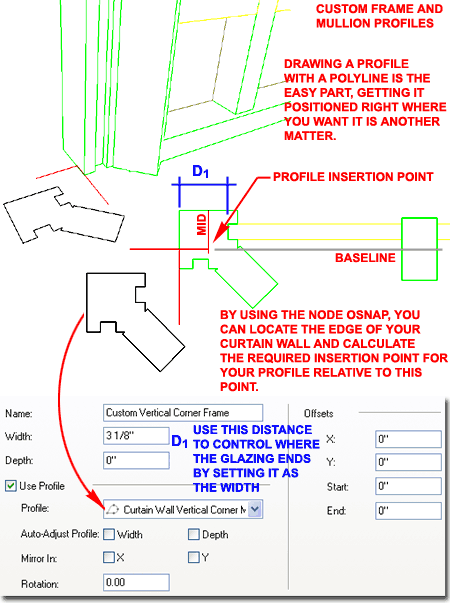 |
|
10Curtain Wall Units |
10-5 CURTAIN WALLS |
Add Curtain Wall Unit
| Alt.Menu |
Design> Curtain
Walls> Add Curtain Wall Unit... |

|
 |
| Keyboard |
CwUnitAdd |
| Links |
Design Rules - Cell
Assignments - for information on where you can insert a Curtain Wall
Unit into a Curtain Wall. |
When you Add Curtain Wall Units,
there is no Properties Palette reaction with
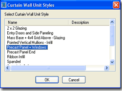 options and settings like with most other ADT objects because, well, I
don't actually know why; even the keyboard version of this object varies dramatically from
other typed commands ( CwUnitAdd instead of CurtainWallUnitAdd ).
Actually, I guess I do know the answer to this peculiarity and it is
because the Curtain Unit really isn't meant to be used as a direct Object
but rather as an insert or filler within a Curtain Wall.
The ability to Add a Curtain Wall Unit allows you to draw it so you can work
on it in an isolated space. Of course, if a Curtain Wall Unit Style
just happens to be the solution you need in place of a Curtain Wall Object,
there is no reason not to Add it like a Curtain Wall options and settings like with most other ADT objects because, well, I
don't actually know why; even the keyboard version of this object varies dramatically from
other typed commands ( CwUnitAdd instead of CurtainWallUnitAdd ).
Actually, I guess I do know the answer to this peculiarity and it is
because the Curtain Unit really isn't meant to be used as a direct Object
but rather as an insert or filler within a Curtain Wall.
The ability to Add a Curtain Wall Unit allows you to draw it so you can work
on it in an isolated space. Of course, if a Curtain Wall Unit Style
just happens to be the solution you need in place of a Curtain Wall Object,
there is no reason not to Add it like a Curtain Wall |
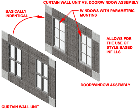
The really significant difference between
Curtain Wall Units and Curtain Walls is that the Units do not allow for
Style Based Infills so you can't create Curtain Wall Units with Doors,
Windows, Assemblies or other Curtain Wall Units. What I recommend is
that you consider using Door/Window Assemblies as Infills whenever you need
to include Doors and/or Windows. |
| Converting
Linework to Curtain Wall Units
Similar to Curtain Walls, use link above for
more information. |
|
| Converting
Layout Grids to Curtain Wall Units
Similar to Curtain Walls, use link above for
more information. |
|
Style Manager - Curtain Wall Unit
| Alt.Menu |
Design> Curtain
Walls> Curtain Wall Unit Styles... |

|
 |
| Keyboard |
CwUnitStyle |
| Links |
Loading Curtain Wall Styles -
for information on how to load ADT Curtain Wall Unit Styles. |
For Curtain Wall Unit Objects, you can use the Style
Manager to load, modify, delete and create new Curtain Wall Units Styles.
Illustrated to the right I show how a Curtain
Wall Unit basically offers all of the same settings and options on the
Design Rules tab of the Style Properties dialog as Curtain Wall Styles. |
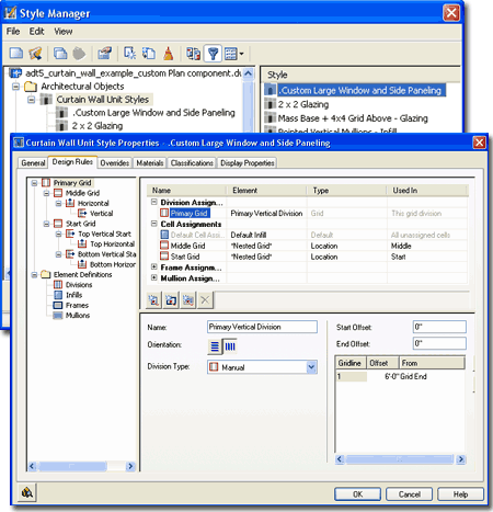 |
|
11Curtain
Walls - Customizing and Tricks |
11-5 CURTAIN WALLS |
| Design Rules - Cell Assignments
- Positions
Starting back at the basic level of creating a custom Curtain Wall Style,
notice how you can Add New Cell Assignments to the "Primary Grid" as
illustrated to the right. Once you have more than one Cell Assignment,
you should find that you will have the option to specify where the new Cell
Assignment will be placed. Under the Type column look for the
Index/Location drop-down list and select the option that is most useful for
your desired result.
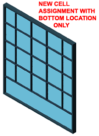 By
using the Location option, you can only choose among three specific Cell
positions: Bottom, Middle and Top or Start, Middle and
End depending upon
the Grid Division Orientation. By
using the Location option, you can only choose among three specific Cell
positions: Bottom, Middle and Top or Start, Middle and
End depending upon
the Grid Division Orientation.
By using the Index option, you can type in the
Index number(s) for the Cell positions; e.g., "1" might be the Bottom, "2"
would be the next one up from the Bottom and "2,5" would be the second
and the fifth.
When you have created a New Cell Assignment, you
should find that the Default Infill is automatically assigned but you can
now provide another Infill option or set it to a *Nested Grid* thus allowing
for a unique Grid Division at this specific Index or Location position. |
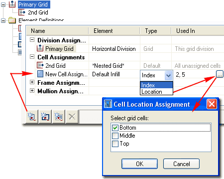
When you design a custom Curtain Wall Style and
find the need for more than one *Nested Grid*, it will be important to chart
out how you are going to divide your Primary Grid: Horizontally or
Vertically. Choosing the right Division Orientation for the Primary
Grid is deceptively of huge importance. I find that sketching out a
diagram on paper helps me to figure out the most logical procedure for
configuring grids. |
|
Transferring Design Rules Data between Curtain Wall-like Styles
Because Door/Window Assemblies, Curtain Walls
and Curtain Wall Units are all based on the same structure, you can actually
transfer design configurations from one Object Style to the Other by using
the Set From... option in the Style Manager. This is far
different from Copying a Style because you are actually copying the data
from another Object Style and not the same one.
This neat feature should be fairly obvious
but did not come to me until I had accidentally designed a custom Curtain
Wall Unit only to realize that it would work far better as a Door/Window
Assembly where I could use real Window Objects. |
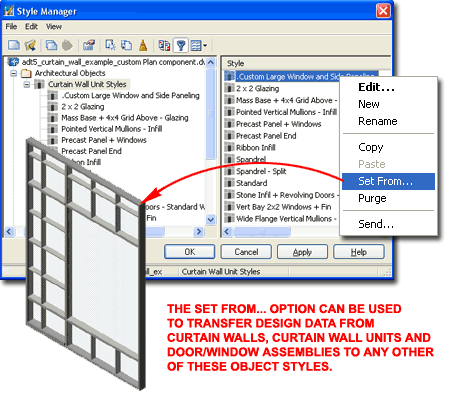 |


 The
mother of all Grids in ADT is the Curtain Wall Object. Users all over
the world are finding new ways to employ this tool for things I am sure the
programmers never dreamed of. I have even attempted to produce a suite
of parametric furniture but due to display limitations for this Object Type,
these currently only work in 3D Views.

 Both
the Imperial and Metric folders contain similar Styles
folders within which you will find one Curtain Wall Style drawing file.
 To begin understanding this object, my advice is
to first visualize it as a 2 dimensional grid in 3D space; in other
words, a grid standing up in the Z-axis instead of lying in the XY plane. In its
most simple form, it can be a single Frame with one Cell
inside. The complexity comes from adding more Cells, altering those Cells and
nesting other objects within those Cells as Infill, but at all times, the Curtain Wall is
still a single Frame. If you draw a Curtain Wall one unit long or 100 units long,
there is still only one Frame there.
 The Add Curtain Walls
Properties Palette is a
deceptively simple interface because it appears as easy to work with at the
one for Adding Walls but the reality is that there is a whole world of
complexity behind the
scenes; within Curtain Wall Styles.
 You can open the
 Converting Walls to Curtain Walls is so
painless a process that I highly recommend this approach during project development.
Since Curtain Wall Style design can be such a time consuming process a designer can
often get caught up in something that isn't as important as it appears. For some
drawings, a slightly modified Wall Style could probably serve as a curtain wall
(especially if elevations are not going to be derived automatically).


 D - Start Miter Angle - the two miter angle options will accept
both positive and negative values, so if you see your miter cut going in the wrong
direction, try the opposite angle value. The miter angle only applies to the top and
bottom Frame components and thus will not automatically cut the right or left Frame or any
Mullions or other components within a curtain wall. To create mitered glass, you
have to remove the right and/or left Frame component. To miter the right and/or left
Frame component, you have to create a right and/or left Frame component that is already
mitered ( usually done with a Profile Style ).
 Illustrated to the right and left, I show a few simple Overrides
and how they were created using the Overrides tools from the object specific
pop-up menu ( select and right click). I also show that I prefer to work
with Cell Markers turned on.


 For Curtain Wall objects, you can use the Style
Manager to load, modify, delete and create new Curtain Wall Styles.
If you have already worked with Door/Window Assembly Styles, you will not
find this subject much different.
 When you select an
Assignment, such as Primary Grid, you should find numerous configuration
options in the Properties View area. The Primary Grid, for example, provides options
for unique Names, Orientation of Cells, Division
Types and corresponding options for these Division Types ( see 1, 2, and 3 ).


 Illustrated
to the left, is another way to access the Display Properties tab; select
the specific object, right click on your mouse
to invoke the object-specific pop-up menu and select Edit Object Display... Just
be aware that when you use this approach, you can actually set an Object Override as
opposed to a Style Override. Object Overrides can be extremely useful because they
allow you to add things like Sills or Thresholds to any object within a Style Family but
they can also be problematic because they lock you out from more centralized, Style level,
controls.


 Draw
Custom Graphics - use this checkbox to allow for the insertion of a
Block in the position of the Component Name. If you elect not to use
this option, you will not be able to Select a Block but you should find that
you will now have a new Display Component Layer - see comments below under
"Other tab".

 Mullions you will find that when you
create a New Curtain Wall Style, there will be two Grids but if you don't
want to use a second Grid, you can set the Cell Assignments to "Default
Infill" or define a custom Infill. For a basic Curtain Wall Style,
do not set the first Cell Assignment to *NONE* because you will
not have a Curtain Wall Object if you do this. Notice that when remove
the *Nested Grid* option as a Cell Assignment, you will find that the
"New Nested Grid" category will drop out under the "Primary Grid"
(Left side Tree View Pane) leaving
you with a very simple and basic Curtain
Wall Style.
 After
you have created your New Curtain Wall Style, you are likely to want to
define the grid layout first. By going to the Divisions category under
Element Definitions in the Tree View of the Curtain Wall Style Manager, you
can modify any default Divisions, Remove, Rename or Add new ones.
 As
with the Horizontal Division discussed above, I show that I have defined a
rather simple Vertical Division to the right. Notice that the
Orientation button is set to vertical lines, that I am using
Fixed Cell Dimensions again set to 2'-0" [610mm] but that I have decided to
Shrink both
Ends so my Curtain Wall will always remain symmetrical.
 Curtain
Wall Grid. Illustrated to the right I show that I have simply changed
the Panel Thickness
to something more appropriate for glass. Later I will discuss how to
mix glass and solid panels for more custom Curtain Wall Styles.
 For
the last part of working with the Desing Rules tab of your custom Curtain
Wall Style, you will probably want to set the Frame
and Mullion
dimensions.
Illustrated to the right I show that the Property Settings for Frames and
Mullions are identical.
 When
creating more complex Curtain Wall Grid Configurations, you have to start
from the outside and work your way inward towards the various Cell
Assignments. Illustrated to the right I show how I have divided a
Primary Grid into Three Vertical Cells. To allow the
Right and Left Cells variable lengths, I show that I have set a Manual
Division Type with a positive and negative distance
from the Grid Middle to my Vertical Mullions. Using this technique
will create a fixed center allowing you to Stretch the Curtain Wall out to
the Right or Left. This Center or Middle Division will always remain
centered so as you Stretch the Grid, the center will automatically readjust.
At times, you may find that you want a set distance from one End instead.
 For
this new Cell Division I show that I have a Horizontal Orientation
set to Manual Division Type with a specific dimension measured
from the Bottom. Using this technique, you can define a head frame or
mullion for such things as Doors and Windows.

 Illustrated
to the left I show how I have Selected one of the Three Cell Assignments as
a sub-grid in the Tree View Pane. For this sub-grid I have left the
Division as set but in order to introduce more Mullions, I added yet another
Nested Grid as a Cell Assignment. In essence this is a sub-sub-grid
that shows up under the parent sub-grid. For this sub-sub grid I show
that I have created a New Division Assignment that I named at "24 inch
Horizontal" to make it easy to read later.
 In
order to force the new "24 inch Horizontal" Division to only affect the top
portion of my grid, I show that I have Select the parent sub-grid and added
a New Cell Assignment that I set to "Default Infill". By adding this
New Cell Assignment, I can use the Location dialog as discussed earlier, to
force the sub-sub grid to the top as illustrated to the left.
 Illustrated
to the right I show that I have Selected the sub-sub Grid created in the
last step and added a Nested Grid as a Cell Assignment to create a
sub-sub-sub Grid. For this deepest Grid, I show that I have added a
New Division Assignment that I have named "24 inch Vertical" and configured
as having a Vertical Orientation, Fixed Cell Dimension of 2'-0" with Shrink
set to Left and Right
 For
the Bottom Cell of the Middle Grid I show that you can use the Cell
Assignments to add things like Door and Window Styles. Notice that
this is also how you add Curtain Wall Unit Styles for even more complex
configurations.

 Illustrated
to the right I show how I have returned to the Primary Grid by
Selecting it in the Tree View Pane. Under the Frame Assignments
category in the Table View I show that I have picked in the "Used In"
column of the Frame row to activate the Frame Location Assignment dialog
where I have unchecked the Bottom button. This will
remove any Frame reference for the bottom of the Curtain Wall Style.

 options and settings like with most other ADT objects because, well, I
don't actually know why; even the keyboard version of this object varies dramatically from
other typed commands ( CwUnitAdd instead of CurtainWallUnitAdd ).
Actually, I guess I do know the answer to this peculiarity and it is
because the Curtain Unit really isn't meant to be used as a direct Object
but rather as an insert or filler within a Curtain Wall.
The ability to Add a Curtain Wall Unit allows you to draw it so you can work
on it in an isolated space. Of course, if a Curtain Wall Unit Style
just happens to be the solution you need in place of a Curtain Wall Object,
there is no reason not to Add it like a Curtain Wall

 By
using the Location option, you can only choose among three specific Cell
positions: Bottom, Middle and Top or Start, Middle and
End depending upon
the Grid Division Orientation.

