Adding
Notes
| Menu |
N.A. |
 |
 |
| Keyboard |
Notes |
| Mouse |
Double Pick on Object,
select Extended Data on Properties Palette and Pick on Notes |
| Links |
|
Notes offer the option to include written
notes about a single object on a drawing or an entire Object Style. The primary
problem with the use of Notes is that there is no obvious graphical indication on the
screen that one or more objects have Notes so find them is a bit of work unless you know
that they exist.
 Illustrated
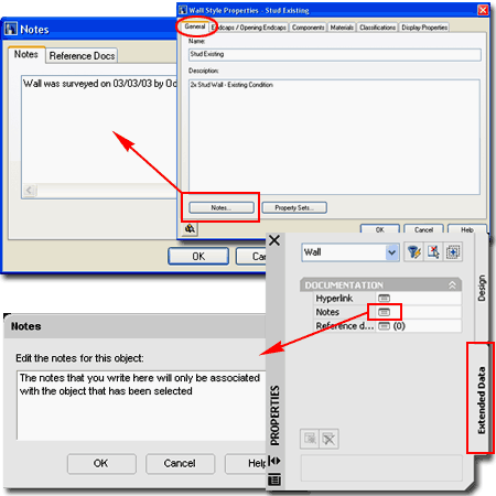
to the right I show to primary ways that you can access the Notes section of an Object
Style or single Object. For Object Styles, simply use the Notes... button
on the Object Style Properties dialog box ( see upper right image ).
For individual Objects, you can use the Properties Palette to
access the Extended Data tab where you will find the Notes icon.
You can also type "Notes" and then Select
an Object to add Notes to. Illustrated
to the right I show to primary ways that you can access the Notes section of an Object
Style or single Object. For Object Styles, simply use the Notes... button
on the Object Style Properties dialog box ( see upper right image ).
For individual Objects, you can use the Properties Palette to
access the Extended Data tab where you will find the Notes icon.
You can also type "Notes" and then Select
an Object to add Notes to.
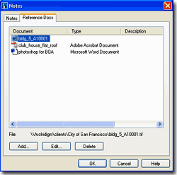
The Reference Docs tab of the Notes
dialog, illustrated left, box is far more interesting and useful than the Notes
part. By using the Add... button you can access your hard drive or
Server and link an unlimited set of file types to the current object. As
illustrated, I show that I have Added a drawing, video, photo and document.
The problem with both options is that we tend to forget
what we don't see and I think in order for either of these options to be useful, a visual
queue is needed so that we remember that information has been added. It is possible
to create such a visual queue by using all sorts of tricks but we would want one that does
not print ( or has that option ) and I would prefer one that isn't a vector object so I
don't end up snapping on it by accident. |
 |
Object
Viewer - Window
| Menu |
N.A. |
 |
 |
| Keyboard |
ObjectViewer |
| Mouse |
Select Object(s),
right-click, select Object Viewer... |
| Links |
|
The Object Viewer is one of my favorite
tools in ADT and when I find myself in regular AutoCAD, I really miss this tool. You
may have discovered that the 3D Orbit tool often behaves poorly with respect to the center
of the objects on your screen. For cases where this happens, just Select your
objects and use this tool instead because it always has the correct center. If you
want to use it as a replacement for the regular 3D Orbit tools, use the Ctrl+A
keyboard stroke before activating the Object Viewer so you will see All Objects in it.
Notice that is has several ADT only tools such as, Display Configurations,
a Set View option and the ability to set the Lens Length
in millimeters ( like a real camera ).
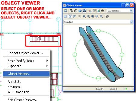
Illustrated to the right, I show how you can use the Object
Viewer to select a set of objects in a complex plan and view it in an isolated mode.
The Object Viewer has all of the same options as those
found when using the 3D Orbit tool; just pick the 3D Orbit button and
right-click to see the full list of options. You can also use the tools from the
toolbar to achieve similar results as those found off of the 3D Orbit pop-up menu.
 If you find a view that you want to present in the working environment, you
can use the Set View button to transfer the Object Viewer's view to ADT's
working view or viewport. If you find a view that you want to present in the working environment, you
can use the Set View button to transfer the Object Viewer's view to ADT's
working view or viewport.
|
 |
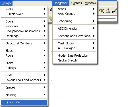
Quick
Slice
| Alt.Menu |
Design > Quick
Slice |
 |
 |
| Keyboard |
QuickSlice |
| Links |
CreateHlr - is likely a better tool
to consider for this type of work. |
Quick Slice is the ultimate 2D projection
tool in ADT but that does not mean it is the best solution for creating sections.
This is the type of tool you use when you have a very specific need or are completely
frustrated with all of the other options ( thus needing the ultimate end ).
Quick Slice is similar to the Slice tool in AutoCAD for
Solid Models and creates a 2D Polyline right through the Selected Objects. It uses
the ZX-plane of the UCS icon as a basis for what plane to slice in so you
can actually use Quick Slice to create 2D polyline representations of Floor Plans.
To cut a 2D Floor Plan, simply rotate the UCS icon on the X-axis by 90 degrees. It
will slice through most ADT Objects, including Mass Elements and it will also slice
through AutoCAD Solid Models.
Though Quick Slice will cut an Xref'd model, it does seem
to perform better if the objects are in their original state rather than within an
Xref. Another thing to keep in mind is that Doors are, by default, open on Models
and thus will not show up in a Quick Slice unless closed. |
Command line steps:
Command: quickslice
Select entities to slice: <select all of the model >
Pick first point: <select a point on the model >
Specify opposite corner: <select a point in the direction of the desired
sectional cut >
[19] polyline(s) created.
Command: |
Reference AEC Objects...
| Menu |
N.A. |
 |
 |
| Keyboard |
EntRef |
| Links |
|
To use, Type EntRef, Select any single
object (including blocks, xref's, elevations, sections or even a line) and then specify a
base point, an insertion point and a rotation angle for the new referenced object.
The concept of Referencing is one, I have to say, that I
have been waiting for in AutoCAD for as long as I have worked with this program. It
allows you to choose an object that controls all of the copies of itself. In a way,
it's like an internal Xref.
Command: _AecEntRef
Entity reference [ADd/Properties/Insertion point/ATtach]: AD
Select an entity to reference: < pick source or parent object >
Insertion point: < Osnap to a base point on source object >
Location: < specify new location for Reference Object relative to base point
>
Rotation angle <0.00>:
Command: |
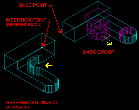 The Insertion point on the Referenced Object provides the only Grip editing
point; thus behaving much like a common AutoCAD Block. Changes to the parent object
reflect in the Reference once they have been completed.
The ATtach option under the
AecEntRef command is really a replace tool. It defers to the base point of the
original Reference Creation, the original Insertion point and then replaces what was
referenced with anything selected. The original base and insertion points remain the
same, so the distance between the new selected object and the original base point are
reflected in the new ATtached object.
Changing the Insertion point,
relates directly to the original Base point so the shift this causes to a reference may
seem inexplicable; i.e, a change in location of the insertion point is accumulative
with respect to its current location. |
Hidden
Line Projection
| Alt.Menu |
Document > Hidden
Line Projection |
 |
 |
| Keyboard |
CreateHLR |
| Links |
|
Hidden Line Projection is the ultimate 2D
solution for generating Elevations in Architectural Desktop. Like the Quick Slice
tool, this tool will project the exterior hidden view on to a flat plane. Any View
can be projected so if you are in need of 2D Isometric Views of your building design, this
is an awesome solution for that type of work. To create a typical Elevation, simply
set the View to Front or other Elevation View, type CreateHLR
on the command line, Select any or all of your Model, pick
an Insertion point for the new projection and answer Yes
to the Insert in Plan View option. The resultant projection will be
a Block but you can Explode it for editing. There is no link to the source data like
the Section and Elevation tools so there is no need to keep the Block in tact unless you
want it that way.
Command: _AecCreateHLR
Select objects: <pick objects individually, by window or crossing>
Select objects:
Block insertion point:< pick a point where you want the elevation >
Insert in plan view [Yes/No] <Y>: Y
Command: |
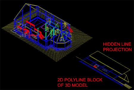 The resultant Projection is a regular AutoCAD block
and can be exploded for editing. The block is made of polylines and usually the
layers and colors come through okay. Once Exploded, you may find numerous redundant
lines that require cleanup. Use the Overkill command from the
Express Tools to remove extra lines. Notice, in the illustration above, that the 3D grade
mesh was also transcribed by this routine; indicating its amazing ability to project
nearly anything to a flat 2D drawing. |
| Convert to 3D Solids
Converting AecObjects to 3D Solids provides the means for
generating solid geometry that is more universal in structure than the special AecObjects
that are based upon Facet Modeling. Solid models are prevalent in the world of
mechanical design and can be used for such things as Finite Element Analysis and Rapid
Prototyping. Solids can be exchanged to other Autodesk products without the
need for Object Enablers. At this time, however, ACIS solids cannot be imported into
Revit.
When you use this tool, you can select All of the objects
in a drawing because it will filter out all objects it cannot convert automatically.
When prompted to "Erase selected entities? [Yes/No]<N>",
it is usually best to respond with a "Yes" or risk having to
work with a lot of redundant entities. In some cases, however, you may simply want
to convert one or a few objects so you can use the Solid
Editing tools to create results that are not possible with the AecObject
tools ( such as Extrude along a Path ).
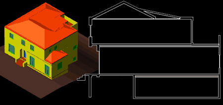
Illustrated to the right I show a sample building before
and after Conversion. Blocks added as custom Components within AecObjects ( such as
Doors and Windows ) are ignored and lost. Multiview Blocks are ignored but not lost. |
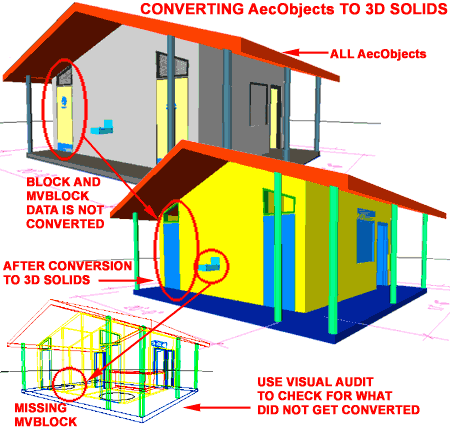
Once you have converted one or more AecObjects
into 3D Solids, you can use the Visual Audit
tool to confirm the conversion success rate.
Command: _AecConvertTo3dSolids
Select AEC objects to convert: All
78 found
14 were not in current space.
10 were filtered out.
Select AEC objects to convert: <Enter>
Erase selected entities? [Yes/No] <N>: Y
Added 23 solid(s) to the drawing.
Failed to convert 22 bodies.
Command: |
Visual Audit
| Alt.Menu |
Visual Audit |
| |
|
| Keyboard |
VisualAudit |
| Links |
|
Visual Audit is a temporary display switch
that turns all AecObjects off so you can inspect the remaining entities to see if there
are problems. This tool can be rather useful after using the ConvertTo3dSolids tool,
discussed above, to assist in determining how many objects were actually converted into 3D
Solids.
The main problem with this tool, however, is that it is
only a temporary display option that does not operate as a true toggle. In other
words, you cannot do any tasks while it is active and you must exit this display mode to
continue working or editing your drawing.
Command: _AecVisualAudit
Press ESC, ENTER or mouse-click to exit: <you must exit to continue working>
Command: |
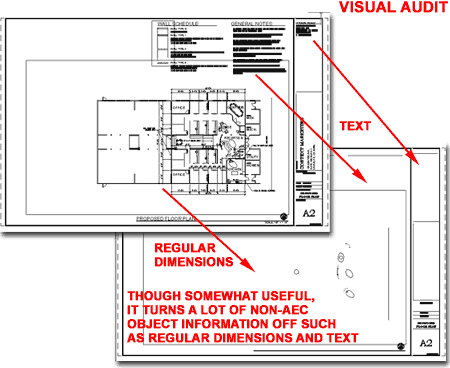
Illustrated above, I show that a lot of
non-aec objects are turned off and though this probably isn't the best audit it did reveal
the few objects I had drawn as normal linework. |
Explode AEC Objects - dialog box
| Alt.Menu |
CAD Manager |
 |
 |
| Keyboard |
AecObjExplode |
| Links |
|
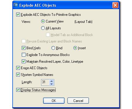
Explode AEC Objects is your salvation to
getting a project out of 3D and down to something more familiar in 2D (
assuming you have a long AutoCAD background ). If you need to Flatten
your drawing and get it into simple "Primitive Graphics" for non-ADT users then
this is one of the best options available. The drawback is that you will likely end
up with a drawing full of dumb objects where Doors and Windows are made up of Lines and
Arcs instead of Blocks.
Explode AEC Objects To Primitive Graphics
- this is probably the most likely option you will select if attempting to create a flat
simple drawing for non ADT users to read. Primitive Graphics means lines, arcs and
blocks
Views:
Current View - the view you are presently in for one view at a
time Exploding. You can Explode the Mode layout or viewports on other Layout Tabs.
All Layouts - will explode the information presented in each
Layout Tab viewport as a separate set of layers with separate entities. Rather than
attempt to Explode all of the various Display Representations via the All Layouts tab, I
suggest running the Explode AEC Objects several times; once for each Display that you want
to convert and then SAVE AS... a name appropriate for those views. If you attempt to
Explode All Layouts you will get a lot of layers because that is how the various view
information will be separated for you.
Model Tab as Additional Block - this option is only available when
you select the All Layouts option and is simply a way of adding the Model Layout too.
If you have a good set of layouts with Viewports showing exactly what you want,
then adding the Model is probably wasteful and redundant.
Reuse Existing Layer and Block Names - this
option still leaves me with questions so I won't elaborate beyond my understanding.
Apparently, if you intend to run this routine more than once, you could end up with
redundant layers so here you can set it to re-use existing layer names. This has to
do with Viewport Mapping of Layers. You can read up on it in the ADT Help menu -
search for Explode AEC Objects. To explore how this works, run it once for one
"Current View" and then return to repeat and should find that you can now
"Re-use Existing Layer and Block Names" for the next run.
Bind Xrefs - this option is the same as
that offered on the Xref dialogue box and is an option I always spend some time pondering
before choosing. With traditional 2D AutoCAD files that needed to be sent off or
archived, this option is very valuable and I typically used the Insert option so that
Xref'd work would remain as a Block. With ADT objects, you may not find the Xref
conversion process very successful, so I recommend using the Explode AEC Objects routine
on the individual files.
Bind - this option brings in Xref work as objects but the layer names all
end up with 0$0 in the place of the vertical bar | ( or
Pipe ) used by the Xref Manager.
Insert - this option brings in Xref work as a block and combines layers if they
are already present in the current drawing. New Layer Names appear as normal layer
names.
Explode To Anonymous Blocks - this option will
convert every ADT object into a Block with wacky names like "*U".
The names are highly undesirable but you do get to keep some cohesive nature to
your drawing. The problem is that no one really wants a drawing full of blocks (
even the Walls become blocks ), so you will probably find that this is not a desirable
option.
Maintain Resolved Layer, Color, Linetype - this
option is a strange one since unchecking it really causes a mess. If left unchecked
many objects end up on layer 0, including Walls, Doors, Windows and even Hatch.
Erase AEC Objects - If Explode AEC
Objects To Primitive Graphic is checked, this option has little
if anything to Erase so it almost becomes irrelevant. If the Primitive Graphics
option is unchecked, then this option will remove all AEC content and leave only non-ADT
objects that were drawn with regular AutoCAD commands; things like Lines, Arcs, Text,
Polylines, etc. |
 Note:
You are probably wondering what options I use. Well, to be totally honest, I am
still struggling with the whole process of dealing with AEC and ARX objects in their
non-native state. Many of my clients are on AutoCAD and work with R14 through
R2000i, so they receive a lot of Proxy objects coming from Land Development Desktop and
ADT. For non-ADT users who do not have the luxury of working with Display
Representations, 3D objects are just not acceptable so Flattening is something that has to
occur.
If you need to send your files to a legacy or
non-ADT user, you will have to consider this problem. Even if they have Object
Enablers to read your ADT objects correctly, they have to deal with 3D points in space and
this can be disastrous.
So far I have had pretty good success with Explode
AEC Objects To Primitive Graphics, Current View only ( one
Display Representation at a time ), No Binding of Xref ( do this
separately and re-thread ), No Explode to Anonymous Blocks ( unless you
want the work of manually Exploding things like Walls ), Maintain Resolved Layer,
Color, Linetype, Erase AEC Objects and Shorten Symbol
Names for R14 Compatibility.
I do not feel that I have completely exhausted
all of the scenarios here so don't hesitate to come up with other possibilities. You
might even run this thing a couple of times, on the same drawing, using different
options to create other results. |

 Illustrated
to the right I show to primary ways that you can access the Notes section of an Object
Style or single Object. For Object Styles, simply use the Notes... button
on the Object Style Properties dialog box ( see upper right image ).
For individual Objects, you can use the Properties Palette to
access the Extended Data tab where you will find the Notes icon.
You can also type "Notes" and then Select
an Object to add Notes to.


