| 1Roofs - Roof Slabs Access |
1-8 ROOFS - ROOF SLABS |
How do I get this toolbar?
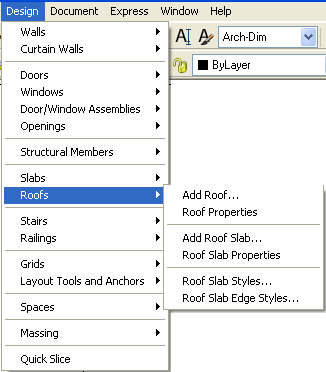
You can also acquire access to some of these commands from the Alternate Design
pull-down menu. From the Design pull-down menu, pick Roofs
> and cascade to their respective command options - see image below,
right. This toolbar is an optional tool and is not needed to use this guide but may
help. |
 |
Roof Slab Tools Toolbar
For Editing Roofs, there are many tools to select from
and you may find them a little more difficult to find in ADT 4 than in the previous two
releases. This is because a lot of these editing tools are now available via
right-click object-specific pop-up menus or through the Properties Palettes. A great
deal of Roof Editing can also be achieved by working with Grips. Illustrated to the
right is the Roof Slab Tools toolbar that provides access to the tools discussed in Part 9 of this guide. |
 |
| Roofs and Roof Slabs pull-down menu and
Tool Palette
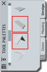 In the first
release of Architectural Desktop, the Roof Object was the only solution
we had for creating roofs but it soon became evident that roofs can easily become far more
complex than any routine can handle so a new Object was introduced in ADT 3.0 called a Roof
Slab. Though the Roof Slab offers greater flexibility in design options, it
can also be more difficult to work with and thus I continue to recommend that designers
start with the Roof Object whenever possible and then convert it to a Roof Slab Object if
that option is required. Of course there are times when it is obvious that using the
Roof Slab Object is the right choice from the beginning, such as flat roofs and thus you
should simply become versed in both types and pick the best option based on experience. In the first
release of Architectural Desktop, the Roof Object was the only solution
we had for creating roofs but it soon became evident that roofs can easily become far more
complex than any routine can handle so a new Object was introduced in ADT 3.0 called a Roof
Slab. Though the Roof Slab offers greater flexibility in design options, it
can also be more difficult to work with and thus I continue to recommend that designers
start with the Roof Object whenever possible and then convert it to a Roof Slab Object if
that option is required. Of course there are times when it is obvious that using the
Roof Slab Object is the right choice from the beginning, such as flat roofs and thus you
should simply become versed in both types and pick the best option based on experience.
Roof objects do not have Styles but Roof Slabs do.
Roof Slabs have another level of complexity involving a sub-Style called a Roof Slab
Edge Style that can be attached to produce custom Soffit and Fascia conditions. |
On the command line, you can type "Roof"
or "RoofSlab" when you want access to many of the Roof and Roof
Slab creation options. For direct access to an option within the Roof or Roof Slab
command-line menu, you can type the primary command plus the option you want direct access
to. For example, if you want to Add a Roof, you can type "RoofAdd"
or if you want to Modify a Roof Slab, you can type "RoofSlabProps"
or "-RoofSlabModify".
Below is the command line read-out for "Roof"
and "Roof Slab":
Command: ROOF
Roof [Add/Convert/Properties/Edit]:
Command: ROOFSLAB
Roof slab [Add/Convert/Modify/Properties/Styles/Edit/edGes/Hole/Dormer]: |
| 2Loading Roof Slab Styles |
2-8 ROOFS - ROOF SLABS |
| Roof
Styles Roof
Objects (not Roof Slab Objects) do not have Styles so you cannot use the
Style Manager to Import specific Roof Configurations. Should you want to acquire the
settings applied to one Roof for a new Roof, you can use the "Match"
option on the command line - see RoofAdd > Match.
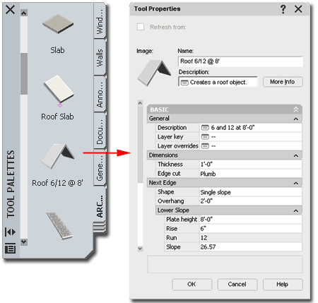
Illustrated
to the right I show another way that you can configure Roof Objects to behave more like
they have Styles. By using the Tool Palette Icons, you can Copy the
Generic Roof Icon and create new ones that hold specific settings that you typically use
such as Thickness, Edge cut, Overhang, Plate height, Rise and so forth. To
distinguish your Roofs, you can use names that indicate what they will create and you can
use the Description field to elaborate on the Name.
See
Tool Palettes Overview
in Part i - Introduction for more information on how to work with Tool Palettes and Icons. |
 |
| Opening
Roof Slab Style templates in the Style Manager
ADT comes with a short list of predefined
Roof Slab Styles that you can access through the Style Manager or
by using the Content
Browser Window ( Architectural Desktop Design Tool Catalog... Roof Slabs and
Slabs ). Much like Slabs, Roof Slabs can be quite simple and you may not need any
of the predefined Styles but since you are likely to want Materials, custom Fascias,
custom Soffits and unique Display Properties, you will probably want to reverse engineer
these Styles to create your own permutations.
 The Roof
Slab Object is nearly identical to the Slab Object and thus you may soon be
wishing for more features for such things as material components, framing options and
better construction tools for intersections, skylights and dormers. One of the
primary problems with the Roof Slab Object is that it, like the Roof Object, measures the
Overhang distance from the Baseline (a perimeter edge at the planar justification point)
or Pivot Point so if you draw a Roof Slab along the inside face of stud or structure, you
have to add the the thickness of the Wall. Unlike the Roof Object, however, when you
use the RoofSlabConvert option, you can specify where you want the Baseline/Pivot Point
relative to the Wall. After creation, there are several options for working
with the Pivot Point and Baseline locations but the Overhang value is always measured from
the Baseline. The Roof
Slab Object is nearly identical to the Slab Object and thus you may soon be
wishing for more features for such things as material components, framing options and
better construction tools for intersections, skylights and dormers. One of the
primary problems with the Roof Slab Object is that it, like the Roof Object, measures the
Overhang distance from the Baseline (a perimeter edge at the planar justification point)
or Pivot Point so if you draw a Roof Slab along the inside face of stud or structure, you
have to add the the thickness of the Wall. Unlike the Roof Object, however, when you
use the RoofSlabConvert option, you can specify where you want the Baseline/Pivot Point
relative to the Wall. After creation, there are several options for working
with the Pivot Point and Baseline locations but the Overhang value is always measured from
the Baseline.
Be
aware that all of the predefined Roof Slab Styles come with Roof Slab Edge Styles already
assigned; hence the "Fascia" and "Soffit" references in their Names.
Even the "Plumb Cut" and "Square Cut" Roof Slab Styles have
Roof Slab Edge Style assignments. |
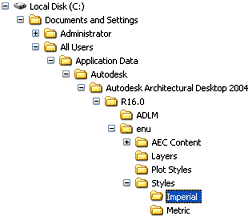
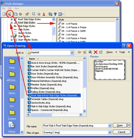 For local installations of ADT,
you are likely to find the Imperial or Metric Roof
Slab Styles in the Styles Folder as illustrated to the
left. The full path to this location may vary but typically it is as
illustrated. On a Network based installation of ADT, these Styles should be on a
captured drive (like "G:\offices standards") or similar location with a folder
name that indicates Styles. Consult your CAD or IT manager if you cannot locate the
Styles Folder.
Roof
Slab & Roof Slab Edge Styles (Imperial).dwg
Roof
Slab & Roof Slab Edge Styles (Metric).dwg |
| Roof Slab Edge Styles
To access and import Roof Slab Edge Styles,
you can use the same Style file discussed above for Roof Slab Styles. Each of the
Roof Slabs Styles comes with Roof Slab Edge Styles so you actually get both when you
import the Roof Slab Styles.
Roof Slab Edge Styles provide the option for designing the
edge condition around the perimeter of a Roof Slab. The general term for these edge
conditions is "Fascia" and "Soffit"
but you can do just about anything you want around the edge as long as it can be created
by extruding a profile shape along the full length of one or more edges. Slabs, for
example, use a "Soffit" to create a perimeter footing detail and that could
actually be used on a Roof Slab as well. You can apply different Roof Slab Edges
along one Roof Slab but you may not always like the automatically mitered corners they
produce. One Roof Slab Edge Style can store two Profiles; one for the Fascia
component and one for the Soffit component. Read more under Roof Slab Edge Styles below.
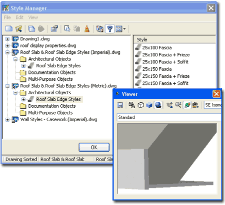
Illustrated to the right I show the Metric
list of Roof Slab Edge Styles. |
 |
| Getting the
most out of the Roof Slab Styles
Because Roof Slab Styles can have Roof Slab Edge Styles as
a Property, you will need to transfer any of the predefined Roof Slab Styles to a Tool
Palette in order to take advantage of these Properties. If you don't turn the Style
into a Palette Icon, you will not get the default Properties as designed for that
particular Roof Slab Style.
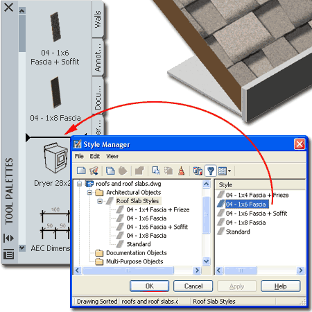
Illustrated to the right I show how you can drag-n-drop a
Roof Slab Style from the Style Manager right on to any active Tool Palette. Once you
have completed this process, you can right-click on the new icon and check the Properties.
You should find that under the Dimensions section of the Tool Properties Palette
that a Baseline edge has been set along with an Edge Style Location path to where this
Edge Style is being imported from. |
 |
| 3Adding Roofs |
3-8 ROOFS - ROOF SLABS |
Add
Roof - Properties Palette
| Alt.Menu |
Design> Roofs>
Add Roof... |
 |
 |
| Keyboard |
RoofAdd |
Since Roof Objects don't have Styles, you must make all of
your design decisions on the Properties Palette - illustrated to the right.
The good news about these options is that you can always edit them
later using the same Properties Palette so don't be afraid to experiment while learning to
use this object on projects. Of the set of options, the most significant is the Shape
which offers three different types that can affect your Roof in very dramatic ways.
For most roof conditions, I find that I start off with a Single Slope and
make adjustments after getting it laid out in Plan View. You should be aware that
ADT typically defaults to a Hip Roof but it is very easy to turn a Hip into a Gable after
creation.
Description - use
this note field to add text based notes about the Roof if you find that it will help
others. You could, for example, explain that the Roof slope may vary or need site
confirmation.
Thickness - use this value field to
specify how high you want your Fascia to measure. Despite the term
"thickness" this option is really not a measure of thickness but of the fascia
height. Be very careful with this value since an Edge cut that is Square
will produce a different roof thickness than one that has an Edge cut of Plumb.
Plumb cuts produce thinner roofs in section. I make an extra effort to point out
this potential problem because it caught me off guard on several occasions when mixing Roofs and Roof Slabs and I couldn't figure
out why the thickness didn't match. For Roof Slabs, the term "thickness"
is a true cross-sectional measurement.
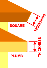 Edge
cut - use this drop-down list to choose between Square and Plumb
fascia cuts. A Square cut is perpendicular to the slope of the roof while a Plumb
cut is always perpendicular to the ground and offers a more common cut when mounting
gutters along the edge. See comments under Thickness for how this affects the true
thickness of the roof object. Edge
cut - use this drop-down list to choose between Square and Plumb
fascia cuts. A Square cut is perpendicular to the slope of the roof while a Plumb
cut is always perpendicular to the ground and offers a more common cut when mounting
gutters along the edge. See comments under Thickness for how this affects the true
thickness of the roof object.
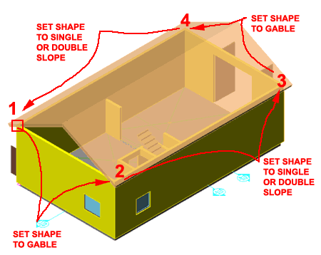
Shape - use this drop-down list to choose
between Single slope, Double slope and Gable
options. You can preset the type of Shape you wish to create before drawing your
Roof or you can make changes while drawing your Roof. You can, for example, start by
using a Single slope for the first two points picked on the screen and then set this
option to Gable for the third point to force the second side to become a Gable instead of
the default Hip. For the fourth point, you will most likely want to set this value
back to Single slope - see below for graphic examples. For Double Slope Roofs, you
will find that you will have a set of "Lower Slope" and "Higher
Slope" options.
- SingleSlope - a planar roof with no
variation from top/ridge to fascia. Can also be used to create shed and flat roofs.
- DoubleSlope - a bi-planar roof with the
potential for slope change between the top/ridge and the fascia. Can also be use to create
sloped flat-top roofs.
Overhang - use this value field to specify
how far out you want the bottom edge of the roof to extend beyond the perimeter edge or
eave. If you draw your Roofs along the inside face of stud, you will need to include
the width of the walls. |
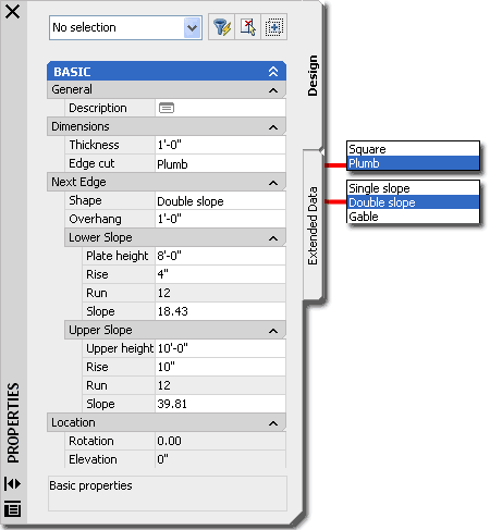 Plate Height - use this value field to specify how
far above the World Coordinate Plane you want the eave of your roof to be placed.
This value represents the plate which is typically measured to the inside face of stud or
wall that the roof members would rest on. If you draw your roof along the exterior
of your walls, the bottom of the roof will be measured to the height specified here so you
can either calculate the adjusted height or draw along the inside of your walls to get a
proper height. If you use the RoofConvert
command and select Walls the Plate Height will automatically be calculated based on the
Wall's height and the roof eave will be set to the exterior. For Upper and Lower
Double Slope Roofs, the Plate Heights can be used to set the Lower Plate along the Wall
and an Upper Height for the Slope Change. This means that you must use a higher
Upper Height on Double Slope Roofs in order to observe any slope change.
Rise - use this value field
to specify the desired rise or change in height relative to the default Run value ( 12
inches for Imperial Units ). If you don't know the rise value, you can use the Slope
value field instead. For Double Slope Roofs, you can use different Upper and Lower
Rise values to create double sloped roof shapes.
Run - always locked but
serves as a unit of measure to specify a Rise against ( 12 inches for Imperial Units ).
Slope - use this value field
as another way of measuring the Rise / Run of a Roof based on degrees. 0 degrees can
be used to create flat roofs. 90 degrees appears to cause errors and 89 degrees
seems to be the current limit depending on the design of your roof.
Tip:
As with all of ADT's Add [object] Properties Palettes, you can change values while
creating a Roof object. This means that you can change slope as you work around the
edges of a Roof or toggle Shape from Single Slope to Gable and back. |
|
Adding Single Slope Roofs
| Alt.Menu |
Design> Roofs>
Add Roof... |
 |
 |
| Keyboard |
RoofAdd |
To Add a Roof
Object, you can either trace the exterior corners of
your building or the interior corners. Given that
the Overhang value is measured from the traced edge and given that when you use the
RoofConvert tool the exterior of the Wall is used, it is clear that the original design
intent for this Object was to work along the exterior; but that's not how roofs are
typically framed so you may have to employ a little extra thinking when designing your
roofs.
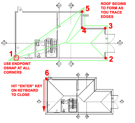
 Illustrated to the right I show a simple scenario using the default approach
to Adding a Roof Object by OSNAPping along the exterior Wall Endpoints
(or Intersection, etc. but I find Endpoints most suitable for this task ). As
illustrated, once you have three or more points, you should begin to see a Roof Object
emerge and as you add more points, the roof will change form. When you have reached
the last point ( numbered "6" in
the illustration ), use the Enter key on the keyboard to close the Roof
Object and close the Properties Palette. Illustrated to the right I show a simple scenario using the default approach
to Adding a Roof Object by OSNAPping along the exterior Wall Endpoints
(or Intersection, etc. but I find Endpoints most suitable for this task ). As
illustrated, once you have three or more points, you should begin to see a Roof Object
emerge and as you add more points, the roof will change form. When you have reached
the last point ( numbered "6" in
the illustration ), use the Enter key on the keyboard to close the Roof
Object and close the Properties Palette.
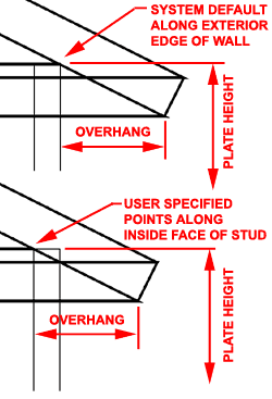
Illustrated to the left I show the
difference between Adding a Roof along the Exterior ( Default ) edge of Walls versus the
Interior Face of Stud. In standard construction practice, a Rafter would rest on the
inside face of stud with a notch cut at the top plate so this would be the more
appropriate solution for a Section but the problem is that the Overhang
value is measured from the edge ( or Eave Component ) so you will need to add the width of
the Walls to produce a correct overhang value.
You do not need Walls or anything else to
Add a Roof object, you can simply pick away on the screen and define a Roof by the points
you pick. Typically, I create Roofs over an Xref of a building's Walls so that my
Roof drawing is separate from the building Walls. By keeping the Roof separate from
other files I have a much smaller and easier to manage file that I use for a Roof Plan and
Roof Framing Plan.
Notice that you can make changes on the
Properties Palette while drawing your Roof - see Adding a Gable Roof below. |
 You do not need Walls or
anything else to Add a Roof object, you can simply pick away on the screen and define a
Roof by the points you pick. Typically, I create Roofs over an Xref of a building's
Walls so that my Roof drawing is separate from the building Walls. By keeping the
Roof separate from other files I have a much smaller and easier to manage file that I use
for a Roof Plan and Roof Framing Plan.
Notice that you can make
changes on the Properties Palette while drawing your Roof - see Adding a Gable Roof below.
Note:
I often find that it is easier to add the default Roof first and then use the Properties
Palette and Grip Editing after creation to change the Roof design.
I also find that I typically start most of my
roof designs with the Roof Object and then Convert it to a Roof Slab as the design goes
beyond what this object can produce. Since the Roof Object remains as a cohesive
single entity it is much easier to manage than the Roof Slab Object. |
Adding a Double Slope Roof
| Alt.Menu |
Design> Roofs>
Add Roof... |
 |
 |
| Keyboard |
RoofAdd |
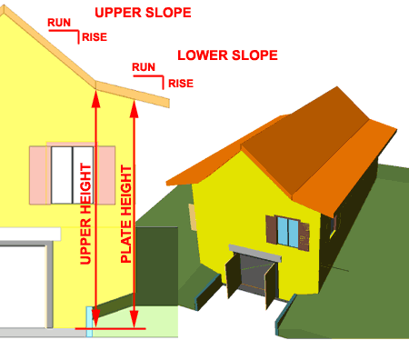
The Double Slope Shape option allows you
to work in exactly the same way as you can with a Single Slope Shape. The DoubleSlope
Shape activates a second set of variables on the Properties Palette that control the
location, by plate height, Rise and Slope of the Upper roof.
In the illustration to the right, I show what a Double
Slope Roof looks like when traced over a simple rectangular building shape.
To see similar results, make sure to set an Upper
Height value that is greater than the Plate Height. |
 |
| Adding a Gable Roof
To take advantage of the Gable Shape
option on the Properties Palette, you need to understand how and when to switch it on and
off. In the illustration to the right, I show the process of Adding a Roof Object
and where I have set the Shape to Gable and then back to Single Slope while tracing the
perimeter of my building. Remember to toggle the Gable Shape Off for each roof
segment that you want as a normal sloped roof.
The trick therefore is to set the Shape to Gable before
picking the next point to form a Gable end.
Note:
The Gable Shape option cannot be left on to form roof designs such as the common four
gable ends design. If you attempt to produce such a roof design, you will find that
you get that "dreaded circle of death". Read below for tricks and consider
using Roof Slabs for such design needs. |
 |
Convert
to Roof
| Menu |
N.A. |
 |
 |
| Keyboard |
RoofConvert |
The Convert To Roof
routine allows you to create a Roof object by either selecting a 2D Polyline
building perimeter or by selecting a set of building Walls. If you,
for example, select a perimeter Pline you should find that you will get the exact same
Roof as you would if you used the Add Roof Properties Palette, using default settings, and
picked the same points that defined the Pline used to Convert to Roof. If you choose
to select your Walls, make sure that you select "No" to the "Erase layout geometry? [Yes/No] <Y>: " 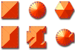 question, otherwise you can actually lose your
Walls. question, otherwise you can actually lose your
Walls.
Using the Pline method is one of my
personal favorites because of how quickly you can make adjustments to the Pline and re-use
it for the Convert to Roof routine. At times you have to experiment a bit to get the
Roof right and if you have to pick all of those points around the exterior perimeter over
and over, it gets rather frustrating. |
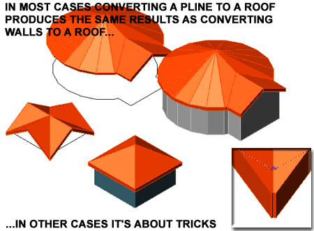 Though not as valuable to know now, in ADT 2 there were no other Roof options
so we found tricks to create other types. Illustrated above, is a trick we
discovered to create double gable-ends on a square; simply notch the corners on your pline
square, convert it to a Roof and Grip Stretch the four unique top vertex points out.
This type of Roof can now be done correctly with Roof Slabs, but I thought I'd
share that trick anyway. |
| 4Modifying Roofs |
4-8 ROOFS - ROOF SLABS |
Modify Roof - Properties Palette
| Alt. Menu |
Design> Roofs>
Roof Properties |
 |
 |
| Keyboard |
RoofProps or
-RoofModify |
| Mouse |
Double right-click
on Roof Object |
| Links |
Add Roof dialog box - for detailed explanation of options |
When Modifying Roof Objects, you will find
that the Properties Palette is nearly identical to the Add version with
the exception of four new options: Edges/Faces dialog, Rotation,
Elevation and Additional information dialog. This
means that you can easily start with a Single Slope Roof, for example, and use the
Properties Palette at a later point in time to change it to a Double Slope.
Edges/Faces - this dialog box provides the
option to work on each edge and face individually with options for Height, Overhang, Eave
Height, Segments and Radius as well as Slope, Rise and Run. See discussion below.
Rotation - this value field provides a
means for rotating a Roof Object in Plan View much like using the Rotate Command.
Elevation - this value field provides the
option for moving a Roof Object up or down in Elevation regardless of what the Plate
Height value is set to. |
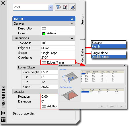 Additional information - this
dialog box provides the means for checking and changing physical coordinate values and
rotation angle. I find this a great tool for fixing accidental Edits rather than
actually using it to Move or Rotate a Roof Object.
Note:
If any value fields have the words *varies* in them, changing the field
will change all of the Roof. |
Roof Properties - Edge and Faces
| Alt. Menu |
N.A. |
 |
 |
| Keyboard |
RoofEditEdges |
| Mouse |
Select Roof Object,
right-click, select Edit Edges/Faces... |
| Links |
Modify Roof - Properties Palette - for another place
to access this dialog |
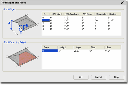
 Under
the Dimensions section of the Roof Properties Palette,
you should find that you have access to all of the changeable features of a Roof. In
the Roof Edges area, you should see a number of Edges
equal to the number of sides to your Roof ( in plan view ). The Edges
start with the number zero ( 0 ), so that can make it a little confusing.
For each Edge, you can make unique adjustments to the Height, Overhang,
Eave, Segments and Radius ( if it
applies ). In addition to the Edge adjustments, you can select an Edge and work with
its corresponding Face in the Roof Faces (by Edge ) area. Under
the Dimensions section of the Roof Properties Palette,
you should find that you have access to all of the changeable features of a Roof. In
the Roof Edges area, you should see a number of Edges
equal to the number of sides to your Roof ( in plan view ). The Edges
start with the number zero ( 0 ), so that can make it a little confusing.
For each Edge, you can make unique adjustments to the Height, Overhang,
Eave, Segments and Radius ( if it
applies ). In addition to the Edge adjustments, you can select an Edge and work with
its corresponding Face in the Roof Faces (by Edge ) area.
Edge - it is virtually impossible to
figure out which edge is where unless you can identify it by a known slope or other value.
I recommend using the Edit Roof Edges/Faces button instead.
(A) Height - in typical cases, the Height
matches the plate but on Gable ends, the Height is zero ( 0" ) as per the graphic on
this tab. You can reverse a Gable end to a Hip by setting the Height to the true plate
height and by changing the matching Face Slope to the desired slope ( something other than
90 degrees ).
(B) Overhang - this is the same value as
that on the Add and Modify Roof Properties Palette.
(C) Eave - to access, double click on the
(C) Eave column label. This deactivates the Slope option on the Roof Face since it
is another way to measure slope. |
 Segments - this option handles the number of
segments a curved roof uses to approximate a curve. You will have more than one
segment as a number and the option to change this value when having created a Roof by
converting a Pline with an Arc in it. Use the RoofConvert command.
Radius - this option controls
the radius of roofs that have Segments in them. See comments for Segments above.
Depending upon the roof design, reducing the radius may not be possible but
increasing it should be possible. This value can also be controlled by using Grips.
Face - there is usually a
single face per Edge but on double sloped roofs, there are two Faces per Edge. By picking
in the blank space below a Face value, you automatically add another Face to your Edge
allowing you to make one Edge a double slope or as many varying slopes as you like. |
Roof Modify - Edges and Faces
| Alt. Menu |
N.A. |
 |
 |
| Keyboard |
RoofEditEdges |
| Mouse |
Select Roof, Right Click,
Select Edit Edge/Faces... and Select the Edge(s) you want to Edit. |
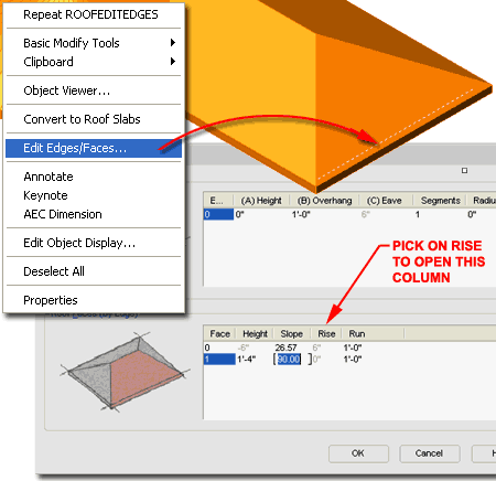
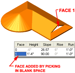 To
make the task of accessing and working on individual Roof Edges easier, you can use the RoofEditEdges
command or object specific pop-up menu option. When you select a roof with this
tool, pick near the bottom fascia or along the top plate where the roof should hit a Wall.
When you select in the right location, you should notice a single line highlight as
illustrated to the right. You can select more than one edge at a time. To
make the task of accessing and working on individual Roof Edges easier, you can use the RoofEditEdges
command or object specific pop-up menu option. When you select a roof with this
tool, pick near the bottom fascia or along the top plate where the roof should hit a Wall.
When you select in the right location, you should notice a single line highlight as
illustrated to the right. You can select more than one edge at a time.
Read comments above for overview of options on this dialog
box.
Illustrated to the right and left I show how you can create
a second face for a single slope edge by picking in the blank area under
the Face column ( usually noted as 0 ). I also
show that I have changed the Slope value of this new Face (noted as 1) to
90 degrees which forces it to become a gable instead of a hip. By
adjusting the Height of the second Face, I have created a unique roof edge that most use
Roof Slabs to create.
Knowing how to change the Slope of any Face allows you to
change Hips to Gables and vise-versa. |
 |
| Roof Modify using Grips Grip
Editing in Plan or Isometric Views provides a very powerful method for working
with Roofs. I typically do most of my Grip Editing in Isometric Views because it is
easier to see the numerous Grips and their effect upon the design.
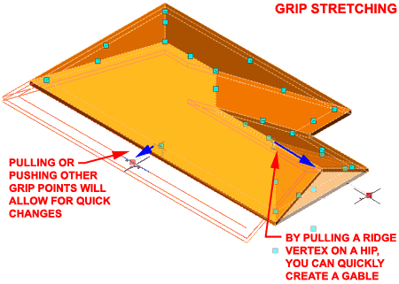
Illustrated to the right I show how easy it is to take the
Hip peak Grip and Stretch it out to form a Gable. When attempting this technique,
make sure to have Ortho on and don't OSNAP to any other objects; simply Stretch the Grip
well out beyond the edge and the transformation will occur.
Another approach to Adding Roofs, is to simply let ADT
take the default route by tracing or Converting the Walls and then you can
|
 |
From Roof Objects to other Objects
| Links |
RoofLine - for more information on using the
RoofLine command on Walls to get them to automatically project up into Roofs - this is one
of the best time-saving commands in ADT. |
| |
RoofSlabConvert - for information on how to convert
Roofs to Roof Slabs. |
At some point in your work with Roofs, you may come to a
point where you don't know what to do next. In some cases it's a simple matter of
knowing the tools you have available to you and in other cases it's a matter of knowing
how to attack the problem with a new object.
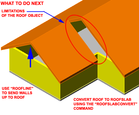
In the illustration to the right a sample scenario where
getting the Walls to come up and meet the Roof is a simple problem that can be solved with
the RoofLine tool. I also show another problem that involves something the Roof
Object just can't do: wrap under itself. In cases like this, it's time to Convert
the Roof Object into a Roof Slab Object
Auto-projecting
Walls to the Roof
To get Walls to automatically run up and match Roof Edges,
Select one or more Wall Objects, right-click, select Roof/Floor Line and cascade over to
Modify Roof Line on the object-specific pop-up menu. On the command line, use the
Auto project option to make the Walls automatically read the Roof Object and project up.
Command: _AecRoofLine
RoofLine [Offset/Project to polyline/Generate polyline/Auto project/ Reset]: A
select walls: ( pick your wall(s) )
select roof: ( pick your roof )
Read more about projecting Walls under Part 3 - Walls Tools |
 |
| 5Roof Display Props |
5-8 ROOFS - ROOF SLABS |
| Roofs Display Property
Overview If I haven't mentioned it enough
already, Roof Objects don't have Styles so you only have the Display Properties to work
with for display changes and you will find that there are only two Display Components to
work with: Roof and Eave.
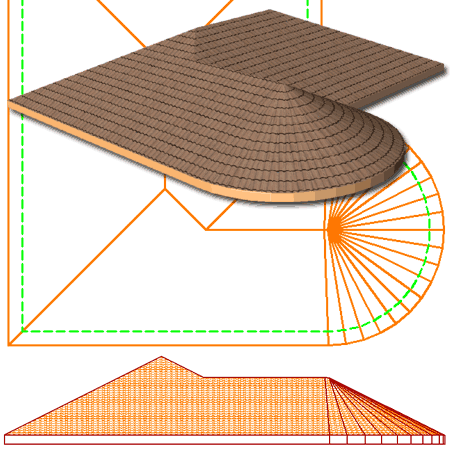
Illustrated to the right I show the Plan, Elevation and
Model Views of a simple Roof Object. As you can see there isn't much to work with
but that is often a delight when compared to some of the more radical Objects in ADT.
For the Plan Display Representation, I set the Eave Display Component to a Green
Color with a Dashed Linetype to show the edge of the Walls Below. Unfortunately, you
cannot turn off the radiating lines on a curved roof without affecting the rest of the
roof so that may pose a problem for your CD's.
The Elevation View takes advantage of the Hatch Component
via the Material that you also see in the Perspective View. To prevent the Hatch and
Mapped Tile Pattern from wrapping around the fascia and under the the Roof, you can set
the "Surface Hatch Placement" to "Top" only.
|
 |
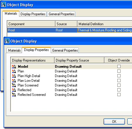
| Object Display - Roof Materials and Display Properties
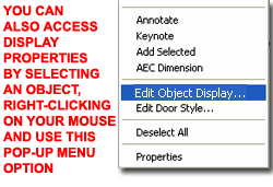 There
are two ways that you can access the Display Properties of Roof Objects: one way is
through the Display Manager and the other way is Illustrated to the left - select the
specific object, right click on your mouse to invoke the
object-specific pop-up menu and select Edit Object Display... There
are two ways that you can access the Display Properties of Roof Objects: one way is
through the Display Manager and the other way is Illustrated to the left - select the
specific object, right click on your mouse to invoke the
object-specific pop-up menu and select Edit Object Display...
Since Roof Objects do not have Styles this is the only
place you can access the Materials and the Display Properties. Illustrated to the
right I show how the Materials tab offers one Component that you can use to control the
hatching and linework for your Roof Objects in Plan and/or Elevations and Sections.
This is where you get a Spanish Tile Pattern in Elevations, Sections and Renderings, for
example.
To the right I also show the default list of Display
Representations on the Display Properties tab. All of these Display Representations
offer the same two Display Components, Roof and Eave, so you should not find these
difficult to understand or work with - see further discussion below.
The subject of Materials is one of the
most expansive and confusing topics in Architectural Desktop because it requires a
complete comprehension of the product in order to take full advantage of this feature;
from object styles to display representations. This subject will be discussed under Part 1 - Display
and in the Presentation eGuide. |
 |
Roofs in Plan
| Menu |
Format> Display
Manager... |
 |
 |
| Keyboard |
DisplayManager |
| Keyboard |
DisplayProps [Attach] |
| Mouse |
Select Object, right-click,
select Edit Object Display... |
| Links |
Part 1 - Display - Object
Display Properties Overview - for more information on how to access the Display
Properties of this Object. |
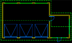 As with the other Objects in ADT, I feel that the
Plan View is the most important to focus on. With Roofs and Roof Slabs, however, it
can probably be argued that Elevations are actually where you get the biggest return on
the investment of using these Objects because, let's face it, you can draw a roof plan
with regular AutoCAD lines a lot faster. As with the other Objects in ADT, I feel that the
Plan View is the most important to focus on. With Roofs and Roof Slabs, however, it
can probably be argued that Elevations are actually where you get the biggest return on
the investment of using these Objects because, let's face it, you can draw a roof plan
with regular AutoCAD lines a lot faster.
Roof Objects do not have a Cutting Plane
setting nor do they respect the Global Cutting Plane value as set by the Display
Configurations. |
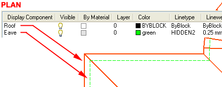 Note:
Notice that when you use the Reflected Display Configuration, that Roofs display in Plan
View. To change this, you may wish to turn Off both Display Components or change the
Roof Display Component to Dashed. The Eave Display Component should be turned Off in
most cases for Reflected Plans and generally I don't show Roofs in Reflected work at all
unless I am illustrating soffit lighting or other roof-related ceiling work. |
| Roofs in Model,
Elevation and Section Roofs use the Model
Display Representation for Elevation and Section Views and you will not find anything
other than the same Roof and Eave Display Components found for Plan. To create other
display results, you will need to work with the Material assignment found on the Materials
tab of the Object Display dialog box. |
|
| 6Roofs - Customizing and Tricks |
6-8 ROOFS - ROOF SLABS |
Arched
Roofs
| Links |
Barrel Vaults - for another possible approach
to solving arched roofs. |
Arched Roofs can be a surprisingly difficult problem to
deal with in ADT because there aren't any straight forward tools to help you create them.
As you can tell by working with both Roofs and Roof Slabs, the planar form is
basically all that you have to work with; hence the term "slab".
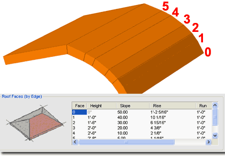
Illustrated to the right I show a trick you might want to
know about if you are determined to create a Roof that simulates an arch form. By
starting with a simple gable Roof, you can use the RoofEditEdges command to modify one face at
a time and break it up into smaller faces that each have greater amounts of slope.
My illustration is a little crude because I didn't bother to calculate the exact heights
and slopes that would make it look more balanced but if you do the work you can get
something fairly reasonable. To be honest, however, I don't have that level of
patience and prefer to use create this type of roof design by using a RoofSlabConvert
trick -Roof Slab Tools - customizing and
tricks. |
 |
| Curved
Roofs
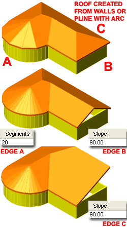
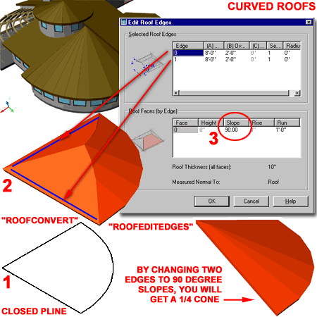
Creating Curved Roofs is actually fairly easy if you use a Closed
Polyline shape as the source for conversion as illustrated to the right. If
you wish to create a true cone, you can use a Polygon to convert ( not a circle ).
Illustrated to the right I show a quarter cone that was
created by using a quarter circle drawn as a Closed Pline. This Pline was then
converted into a Roof object by using the "RoofConvert"
command. In the illustration to the right, I show what happens when the conversion
has been processed and since the result is not a quarter cone, I show that I had to use
the Edit Roof Edges dialog box to change the slope of two sides to 90 degrees.
To Edit Roof Edges, use the "RoofEditEdge"
command and select the edges that do not have the correct slope (
illustrated with a blue line ). On the Edit Roof Edge dialog box, you should see a
Slope option for each Edge ( see number 3, right ). Change the Slope
to 90 degrees for each edge and the result should be similar to that
illustrated in the lower right.
Finally, you can create a more smooth curved roof by
editing the curved edge and changing the Segments value on the Edit Roof Edges dialog box
to a number high enough to meet your desired appearance.
|
 |
| Mixing Roofs and Roof
Slabs
See links above for more information on some potential
problems for mixing these two Objects and for some tricks on how to merge them into a new
single Object. |
|
| 7Adding Roof Slabs |
7-8 ROOFS - ROOF SLABS |
Add Roof Slab - Properties Palette
| Alt.Menu |
Design> Roofs>
Add Roof Slab... |
 |
 |
| Keyboard |
RoofSlabAdd |
The Add Roof Slab Properties Palette
provides the ability to choose Styles, Modes (for how to draw), Slope, Thickness, Base
Height, Overhang, four Justification methods and (like the Add Wall Properties
Palette) two methods for Closing - Ortho Close and Polyline Close.
Style - a drop-down list offering a list
of currently loaded Roof Slab Styles. Type RoofSlabStyle or use the Content Browser
to load other Styles.
Mode:
Direct - this method allows you to pick the perimeter points for your Roof Slab
at the exact 3D points in space where you want your Roof Slab to sit. This means
that if you pick points along the top of a set of Walls that have the same plate height,
you will get a perfectly flat Roof Slab. If you want a Roof Slab at a slope, you
will have to pick points that define the slope; this is why the Slope options are not
accessible.
Projected - this method is much like the Add Roof routine where you pick
points along a 2D plane but you actually get a "projected" slope.
In both the Direct and Projected Modes, the first two
points picked establish the fascia.
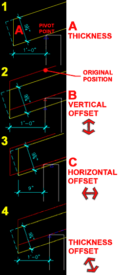
A - Thickness - is the actual
roof slab mass thickness as illustrated by the letter "A". The question
is, do you include finishing materials or set it just for the framing (lumber) dimension.
I prefer to work with the framing sizes.
B - Vertical Offset - this
value basically moves the Roof Slab up and down parallel with the wall or perpendicular to
the ground but can be confusing when mixed with the Thickness Offset value on the Design
Rules tab. The Pivot Point is affected.
C - Horizontal Offset - this
should be an easy one to comprehend; you are just moving the Roof Slab back and forth on
the plate line. The Pivot Point is affected.
Justify - Top, Center, Bottom and
Slopeline are designed to work with the Direct Mode but you can get some
limited functionality out of these justifications for the Projected Mode (see comments below). Since Direct Mode allows
you to pick the specific 3D points that define a Roof Slab and its slope, the
Justification options allow you to determine where the Roof Slab should be positioned (
along the z-axis ) relative to those picked points. This is much like deciding to
create a Roof based upon the Top, Bottom or Centerline along a Rafter or Fascia board.
Slopeline is determined by the Offset Thickness
value on the Design Rules tab of a Roof Slab's Style.
Base Height - height from Z=0 for the
pivot point. Using the Bottom Justification, I like to think of this as the Plate
Height along the top of my Walls.
Direction - this option
affects the direction of your roof when you use the Ortho Close option (
command line only ) and only works if you use Ortho Close after having picked a second
point. The second point establishes the front of your roof ( or fascia ) thus
allowing ADT to calculate a Left or Right direction of "closure".
Overhang - the distance from
the insertion point ( where you pick ) out to the Roof Slab's edge ( not including any
fascia boards, gutters, etc. ).
Baseline Edge - a drop-down
list offering access to all Roof
Slab Edge Styles in the current drawing file. Use these Edge Styles to
define a profile shape along the Baseline Edge side ( a.k.a. fascia or front ) of your
Roof Slab. This is how you add a gutter, for example. You can also set this
information at a later time using the Modify Properties Palette.
|
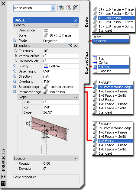
Perimeter Edge - a drop-down
list offering everything discussed for option "Baseline Edge", but for all of
the remaining sides. I don't like this option because it will add the Edge Style to
edges you may not want and Edge Style attached to; like the ridge between two roofs.
I prefer to use the Modify Properties Palette for this work.
Rise - Run - Slope - you can
input Rise and Run numbers that will automatically calculate an Slope angle for you or you
can specify an angle. Adjustment or change in slope occurs around the Pivot Point as
established upon creation of the Roof Slab or by adjustment on the Pivot Point value
fields. The Pivot Point can also be modified directly on the Roof Slab Modify
Properties Palette. Special Options on the Command Line:
Ortho close - if used after
picking a second point this button will create a rectangular roof based upon the dimension
of the first two points ( basically a square with extra for soffit, etc. as per the Style
). It can also be used after a 3rd point has been picked but then the Direction
options become invalid ( this is a nice quick way to finish a Roof Slab though ). The
Direction of the Roof Slab will be based upon the direction established by your second
picked point and the Direction buttons ( see Direction description ). If used after
picking three or more points this button simply calculates what it will take to create an
orthogonal closure from the last point picked relative to the first point picked.
Close - only available if
three or more points have been picked and simply closes a Slab shape to form a polyhedron
much like Close on a Polyline. |
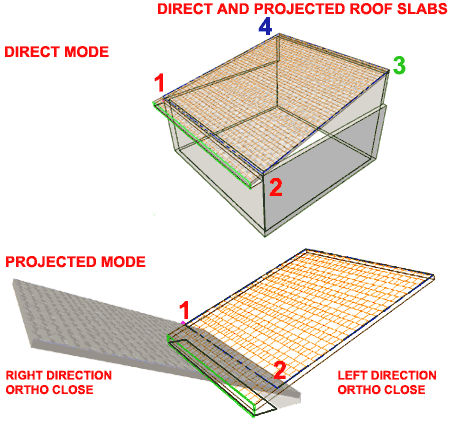
| Add Roof Slab - Direct Mode & Projected Mode When Adding Roof Slabs, you may find the Mode and Direction options a little
confusing so I have illustrated the difference to the right by using the Ortho Close
technique after drawing the first two points for the two example Roof Slabs.
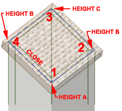 The
Direct Mode method of Adding a Roof Slab assumes that you know the pitch
by the virtue of the 3rd point you pick. If you don't pick a 3rd Point in Space that
happens to be higher on the Z-axis than the 2nd point, there will be no slope
change. Using the Left or Right Direction options really make no sense for this type
of Roof Slab creation since the Directions apply to the command-line "Ortho
Close" option and together these two options only work after the second point has
been selected ( not the third or more points). In other words, you can't select the
third point to establish the Slope so use this whole combination of options only when you
want no Slope Roof Slabs. The
Direct Mode method of Adding a Roof Slab assumes that you know the pitch
by the virtue of the 3rd point you pick. If you don't pick a 3rd Point in Space that
happens to be higher on the Z-axis than the 2nd point, there will be no slope
change. Using the Left or Right Direction options really make no sense for this type
of Roof Slab creation since the Directions apply to the command-line "Ortho
Close" option and together these two options only work after the second point has
been selected ( not the third or more points). In other words, you can't select the
third point to establish the Slope so use this whole combination of options only when you
want no Slope Roof Slabs.
The Direct Mode method can be extremely useful when you
need to add a new Roof Slab whose exact angle or slope is not known but can be derived
from points along other objects. You can also use this method to create compound
roof pitches ( slope in two directions ) if you have the Wall Slopes already calculated -
see illustration to the left.
The Projected Mode method of Adding a Roof
Slab works much like the Roof routine and allows you to specify the Slope and Base Height
before picking your points. This means that you can pick two points anywhere in
space to establish the baseline ( fascia ) and either use the command-line "Ortho
Close" or continue picking points. Just like the Direct Mode method, the
first two points will establish the Fascia. If you want a square Roof Slab, simply
use the Direction options ( Left or Right ) together with the command-line "Ortho
Close" option after having picked the 2nd Point and the job will be complete.
|
 Notice that for both Roof Modes you can always use the
command-line option "Close" after having picked a 3rd Point. For me, I
never bother with the Direction Options or the "Ortho Close" since using a 3rd
Point not only establishes the direction but also the length and the slope ( when using
the Direct Mode ). I always draw Roof Slabs using the Direct Mode in Isometric since
I need so see and OSNAP to the points that define it and I generally draw Roof Slabs using
the Projected Mode in Plan where the command-line "Ortho Close" tends to work
rather well after the 3rd point has been picked - for some reason it doesn't work in
isometric modes though. |
| Add Roof Slab - Justifications As stated under the Add Roof Slabs - Properties Palette, the
Justification options are designed for use with the Direct Mode of adding a Roof Slab.
This technique requires that you actually pick points in space that define the
plane of the roof, including the slope. Though the Direct Mode method is nice at
times, I don't find it to be the most common approach to creating roofs so that makes the
Justification options a bit of a problem.
Top, Center, Bottom and Slopeline Justifications all work
as expected when using the Direct Mode to create Roof Slabs but the don't work as expected
when using the Projected Mode. Illustrated to the right I show the "expected
solutions" for Bottom, Center and Top Justifications and below I discuss the results
you get when using these with the Projected Mode.
Justifications - Projected Mode
Top - does not work correctly - to get
this feature to work better, you must either make manual adjustments to the Offsets or
design a Roof Slab Style with a Fixed Thickness and an equal amount of Offset on the Design Rules tab of the Roof Slab Style dialog
box.
Center - never works correctly
Bottom - works correctly when no Offset is
specified on the Design Rules tab.
Slopeline - works correctly both with and
without Fixed Thickness and Offset values. |
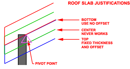 Note:
In most cases we tend to build roofs from the inside face of a wall along the top plate
using the Bottom Justification. If you use this Justification with the Projected
Mode, you should not have any problems unless the Roof Slab Style has a preset Offset
value on the Design Rules tab
of the Roof Slab Style dialog box. Guess what, all of the predefined style in the
Content Browser have preset Offset values so watch out for those Styles. |
Convert
to Roof Slabs
| Menu |
N.A. |
 |
 |
| Keyboard |
RoofSlabConvert |
| Mouse |
Select a Roof Object,
right-click and select Convert to Roof Slabs |
| Links |
Roof Slab Properties - Edges
tab |
| |
FacetDev - this
variable can be set to control the facetting of curved slabs when Converted from curved
Plines. Set before converting. Lower numbers = better curves. |
The Convert to Roof Slabs tool can be used
to convert Plines, Walls or Roofs to
Roof Slabs. In my own experience working with both Roofs and Roof Slabs, I have
found that I get the best results by first using Roof Objects that I then Convert to Roof
Slabs Objects. The reason for this technique has to do with the ease of generating a
Roof Object and the Grip options for reshaping it. As a job moves from Design
Development to more accurate Construction Documents, I use this Convert option so I can
add Roof Slab Edges, cut Holes for Skylights, Trim intersections and much more.
Unfortunately you cannot convert Roof Slab Objects back to Roof Objects so be aware that
this is a one-way process and you may want to keep your original Roof Object around in
case you need to revert back to an earlier phase (since the Roof Object is kept on a
separate Layer this is simply a matter of turning a Layer On or Off)
Tips on Converting:
One of the main things to understand about Converting to Roofs/Roof Slabs is the
difference between how these two routines work. The Convert to Roof routine was designed
to handle a full space, like that created by the perimeter walls of a building. The
Convert to Roof Slabs routine was designed to convert a single object, like one
Wall. It can be used to convert many walls, for example, but each wall produces a
unique slab. One of the biggest problems between the two, is that Roof Slabs usually
don't come together as one nice roof but several overlapping slabs and often end up
sloping from the wrong direction; particularly on curved walls. |
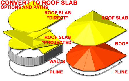 If you can begin with a Roof object you will probably find that method far
faster. Use the Convert to Roof routine first and then convert that Roof object to a
Roof Slab.
Use the Direct option or a Roof Slab Style
with a slope of 0 degrees to create flat roofs.
The pivot point on closed Pline shapes occurs
at the first point picked to create the Pline and the slope is established by the
direction of the second point. If the second point is an Arc, the slope will be
established by the direction of the Arc but won't slope off of the Arc. |
| 8Modifying Roof Slabs |
8-8 ROOFS - ROOF SLABS |
Modify Roof Slab - Properties Palette
| Alt.Menu |
Design> Roofs>
Roof Slab Properties |
 |
 |
| Keyboard |
RoofSlabProps [-RoofSlabModify] |
| Mouse |
Double pick on a Slab Object
with the left mouse |
| Links |
Tool Palettes - for information on setting
Defaults within the icon buttons for faster productivity |
For Modifying Roof Slabs you can use the
ubiquitous Properties Palette which will offer most of the same options
and settings found on this Palette when Adding Roof Slabs. One of the more
interesting and useful options you will find on the Properties Palette is the Edges
dialog, illustrated right, which will allow you to work on each edge so you can attach
things like Fascia boards, gutters and Soffit trim.
 Style - allows you to change the selected Roof Slab
to any other Roof Slab Style currently loaded in your drawing file. Style - allows you to change the selected Roof Slab
to any other Roof Slab Style currently loaded in your drawing file.
A - Thickness - this option will not be
available if it has been set as "Has Fixed Thickness" under the Design Rules tab
of the Roof Slab Style.
B - Vertical Offset - this
value basically moves the Roof Slab up and down parallel with the wall or perpendicular to
the ground but can be confusing when mixed with the Thickness Offset value on the Design
Rules tab because that value controls the vertical origin of the offset.
C - Horizontal Offset - this
should be an easy one to comprehend; you are just moving the Roof Slab back and forth on
the plate line. This option is also affected by the Thickness Offset on the Design
Rules tab - see comments for B - Vertical Offset.
Edges - this cell, when
picked, activates the Roof Slab Edges dialog
box illustrated in the upper right and discussed below. Use this tool to Add or
Modify edges for such things as fascia boards and gutters.
Rise - Run - Slope - see Add Roof Slab Properties Palette
above.
Hold fascia elevation
- this drop-down list offers three choices for holding the Fascia Elevation
fixed on the Vertical axis. Use "By Adjusting Overhang"
when you are trying to keep the seat cut the same ( note: this actually only
works correctly if you move the pivot point to the inside of your plate).
Use "By Adjusting Baseline Height" when you want to keep
the same exact fascia and overhang but are willing to drop the Roof Slab (
or rafter ) down to achieve this result ( a deeper seat cut ). Use "No"
when you just want the Roof Slab to pivot naturally off the Pivot Point with
no formulaic interference.
|
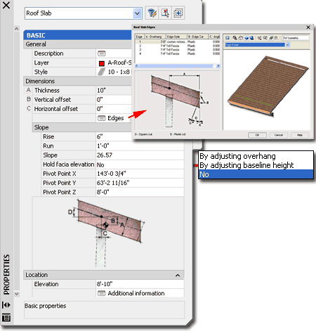 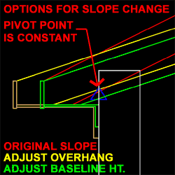 Pivot
Point X,
Y and Z - a very important modification
option because it allows you to move the point at which your Roof Slab
pivots with respect to any change in the Slope. Suppose, for example,
that you have calculated the ridge of your roof from a particular Wall but
you are uncertain about where the fascia should end up - you can move the
Pivot Point to the calculated ridge and set the slope from there to assist
you in finding out where the fascia will actually sit. You may
also find it necessary to move the Pivot Point to match how you expect your
Rafters to be seated on a Plate. Pivot
Point X,
Y and Z - a very important modification
option because it allows you to move the point at which your Roof Slab
pivots with respect to any change in the Slope. Suppose, for example,
that you have calculated the ridge of your roof from a particular Wall but
you are uncertain about where the fascia should end up - you can move the
Pivot Point to the calculated ridge and set the slope from there to assist
you in finding out where the fascia will actually sit. You may
also find it necessary to move the Pivot Point to match how you expect your
Rafters to be seated on a Plate.
Elevation - this value field provides the option
for moving a Roof Slab Object up or down in Elevation regardless of what the Plate Height
value is set to.
Additional information - this
dialog box provides the means for checking and changing physical coordinate values and
rotation angle. I find this a great tool for fixing accidental Edits rather than
actually using it to Move or Rotate a Roof Slab Object.
Note:
Notice that there is no option to change the Justification here so you may find yourself
having to use Move, Rotate and other AutoCAD command to make this type of change. |
| Roof Slab Properties - Edges tab
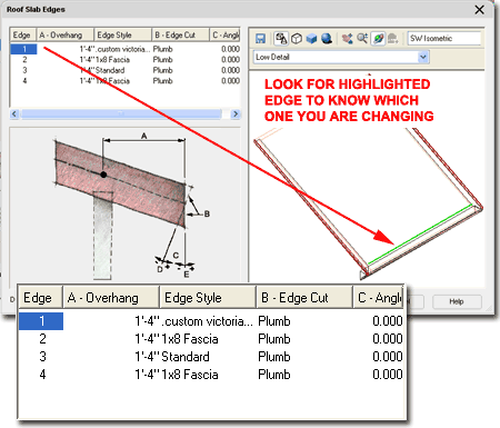
On the Roof Slab Edges dialog box,
you can assign overhang values, fascias, soffits and rafter cut angles. If
you specified an Overhang value on the Properties Palette when you added this Roof Slab,
you will see that Overhang value set here for Edge number 1. To identify Edges, you
should see a line with a highlight color in the right preview pane as illustrated.
By holding the Shift-key down, you can Select a whole set of Edges and make common
settings rather than doing the work one-at-a-time.
To Add or Remove Edges you can use the Add or Remove Vertex tools.
Overhang - this value is measured from the
baseline edge so if you created your Roof Slab based on points selected along the inside
face of stud or structure, be sure to add the width of the Walls for a proper Overhang
value.
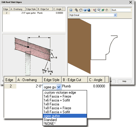
A - Edge Style - this drop-down list will
provide access to the "Standard", "*NONE*" or any
Roof Slab Edge Styles available in the current drawing file. You typically do not
want any Edge Style for Edges that meet other Roofs or Walls. "Standard"
is actually an Edge Style where "*NONE*" guarantees that no
edge changes might occur through inadvertent Roof Slab Edge Style changes. At times
you may wish to add an Edge Style just to assign a unique Material to that portion of your
Roof Slab design.
|
 B - Edge Cut - the drop-down list offers
two options: Plumb and Square. The Plumb cut is perpendicular to the ground plane
and is a typical cut for conditions where gutters are attached. The Square cut is
perpendicular to the Roof Slab itself.
C - Angle - this value field provide the
means for adjusting the Angle relative to the Edge Cut setting ( Plumb or Square ) for
even greater flexibility in the cut angle. This is also where any unusual Roof Slab Cut
angles are stored if you combine the UCS icon with the Roof Slab Cut tool. |
Edit
Roof Slab Edges
| Menu |
N.A. |
 |
 |
| Keyboard |
RoofSlabEdgeEdit |
| Mouse |
Select Roof Slab,
right-click, Select Edit Edge/Faces... and Select the Edge(s) you want to Edit. |
| Links |
Roof Slab Properties - Edges
tab |
T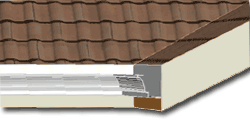 he Roof Slab Edit Edges tool
offers you direct access to the Edges tab of the Roof Slab Properties dialog box.
When using this tool, you need to select one or more Roof Slab Edges by picking near them
or directly on the perimeter line ( usually displayed as a blue dashed line). If you
have a rather complex Roof Slab with many edges, this is a great way to isolate just those
edges that you wish to edit so you don't have to hunt for their index number on the Roof
Slab Edges dialog box. he Roof Slab Edit Edges tool
offers you direct access to the Edges tab of the Roof Slab Properties dialog box.
When using this tool, you need to select one or more Roof Slab Edges by picking near them
or directly on the perimeter line ( usually displayed as a blue dashed line). If you
have a rather complex Roof Slab with many edges, this is a great way to isolate just those
edges that you wish to edit so you don't have to hunt for their index number on the Roof
Slab Edges dialog box.
You cannot select edges of different Roof Slabs.
See comments on Roof Slab Properties - Edges
tab. |
 |
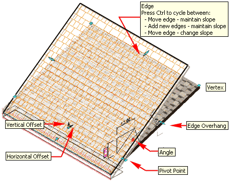
| Roof Slab Grip Points Roof Slabs have the same set of Grip Points that Slabs do.
Illustrated to the right I show an Isometric View of a simple Roof Slab Object where you
can see most of the numerous Grip Points. Of the set, my favorites are the Angle,
Edge and Edge Overhang.
For the Angle Grip, after you have
selected this Grip and made it Hot ( Red ), you can use the Tab key on
your Keyboard to cycle through the three options for changing the values: Rise,
Run or Angle.
For the Edge Overhang, make sure that you
use the appropriate Grip Point since this value is the Overhang and not the Roof's Edge
which has a Grip that can be in nearly the same position if no Overhang exists.
For the Edge Grip, notice that you can use
the Ctrl key on your Keyboard to change what this Grip actually does to
your Roof Slab. After Selecting the Grip and making it Hot, you can use the Ctrl
key. If you wait a second while holding the mouse still over the Grip, you will get
a pop-up indicating which of the three modes you are in. The Add new edges mode, add
edges to the sides so it's not quite like adding Vertex Points along the front. The
Move edge and change slope mode allows you to OSNAP to other Objects, like a Ridge Line of
another Roof Slab, while calculating the new slope. This is a neat feature but roofs
are rarely framed by arbitrary slopes so be careful about using it.
See Modify
Roof Slab - Properties Palette - for information on the other Grip Points. |
 |
Roof Slab Tools
| Menu |
N.A. |
| |
 |
| Mouse |
Select Roof Slab,
right-click to access menu illustrated right. |
| Links |
Part 9 - Roof Slab Tools - for the whole story on the
editing tools for Roof Slabs |
|
Like
Slabs, Roof Slabs have a whole suite of tools for such tasks as Extending, Trimming,
Cutting Holes and creating Dormers. Read Part 9 - Roof Slab Tools for more
information on Modifying Roof Slabs. |
| 9Roof Slab Style Properties |
9-8 ROOFS - ROOF SLABS |
Style Manager - Roof Slabs
| Alt.Menu |
Design> Roof
Slabs> Roof Slab Styles... |
 |
 |
| Keyboard |
RoofSlabStyle |
| Links |
Object Style Management - for more
information on Object Styles |
For Roof Slab Styles, you can use the Style
Manager to load, modify, delete and create new Roof Slab Styles.
Though you can easily create New Roof Slab Styles from
Scratch using the New button, you may want to use the Copy/Paste
technique instead because it is far easier to Modify Settings of an existing Object Style
than it is to create one from Scratch. In some cases, you may even miss specific
settings that can come back to haunt you much farther down the road on a project - things
like Display Representations or Data for Schedules.
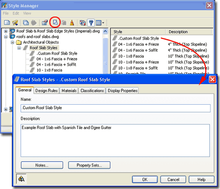
Illustrated to the right I show the process of creating a New
Roof Slab Style that I have Named "Custom Roof Slab Style".
By double-clicking on this new style, I show that I have also activated
the Roof Slab Styles Properties dialog box where all of the custom
settings can be made for the size, shape and look of this particular object style.
The General tab provides access to the Name
and Description fields for a Style; plus access to the attachment of Notes
and Property
Sets. |
 |
| Roof Slab
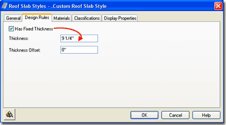
Styles - Design Rules tab On the Design
Rules tab of the Roof Slab Styles dialog box, illustrated to the
right, you will find a checkbox that locks the A - Thickness value field
on the Properties Palette and two Thickness options.
 Has Fixed Thickness - check this box to lock in a Roof Slab
Style's Roof thickness value so that it can't be changed except through the Style.
When you check this to fill in a value for Thickness, you will also be deactivating the A
- Thickness value field on the Properties Palette. Has Fixed Thickness - check this box to lock in a Roof Slab
Style's Roof thickness value so that it can't be changed except through the Style.
When you check this to fill in a value for Thickness, you will also be deactivating the A
- Thickness value field on the Properties Palette.
Thickness - use this value field to set
the Fixed Thickness value.
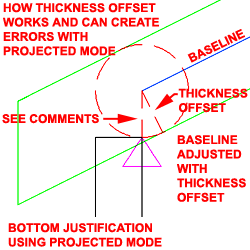
Thickness Offset - use this value field to
control the Baseline position of a Roof Slab relative to the Pivot Point and measured
perpendicular to the roof plane ( i.e., same as thickness ). This does not affect the
Pivot Point like B - Vertical Offset does; i.e., the pivot point remains
fixed at the original insertion point unless otherwise modified. When you modify
this value you also reposition the vertical origin of the Thickness Value (somewhat
pointless), Horizontal Offset and Vertical Offset allowing you to make adjustments in a
triangular fashion; e.g., move a Roof Slab from 3 units up perpendicular to the slope
(Thickness Offset), over 2 units (Horizontal Offset) and down 2 units (Vertical Offset). |
 Note:
In the graphic illustration to the left I show how the Thickness Offset value affects the
position of the Baseline. The problem is that if you don't work with Direct Mode
when Adding Roof Slabs, the Thickness Offset value seems to get translated into the
hypotenuse of the triangle I show as dashed red lines and this translates to a nasty bit
of error in the position of the roof. |
| Roof
Slab Styles - Materials tab
The subject of Materials is one of the
most expansive and confusing topics in Architectural Desktop because it requires a
complete comprehension of the product in order to take full advantage of this feature;
from object styles to display representations. This subject will be discussed under Part 1 - Display
and in the Presentation eGuide.
Illustrated to the right I show that Roof Slabs will offer
one predefined Component ( Slab ) and that the Material
Definition Name will be set to "Standard" when you create a Style from
scratch. If you have imported any of the Architectural Desktop Roof Slab Styles
from the Object Style Library, you should find that you will be able to use the Material
Definitions that come with those objects - as illustrated to the right where I am
selecting Spanish Tiles.
|
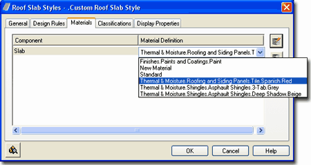 Though you are not required to use Material Definitions in
Architectural Desktop, you are likely to find it difficult to avoid using them since most
of the predefined Styles use them. Materials have thrown a monkey wrench into the
whole Display System because they can actually take over control of how your linework
appears in Plan View for Construction Documents ( discussed below under Display Properties
). The best thing to do when learning about Material Definitions is to match how
most of the predefined Roof Slab Styles have been configured; i.e., reverse engineer the
ADT Styles. |
| Roof
Slab Styles - Classifications tab
The subject of Classifications is
thankfully no where near as complicated as that of Materials so the only real question you
will need to consider is if you need to use them. Classifications offer another way
to separate Object Styles into categories that can be used in Schedules
and even in Display Representation Sets ( as "Show"
or "Hide" ).
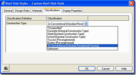
Illustrated to the right I show that I have one Classification
Definition ( see Format pull-down menu) with a list of Classification
Names or Types. Generally you will not have any options on this Tab but if
you have created at least one Classification Style that has been set to "Apply
To" Roof Slab Styles, you will be able to use it here. The range of use is
really up to your imagination but it is fairly obvious that Classifications can be quite
handy in Schedules. This topic will be discussed further under Part 18 -
Schedules. You can also read a bit more about how to create Classification
Definitions in Part 1 -
Display. |
 |
| Roof Slab Styles - Display Properties
tab
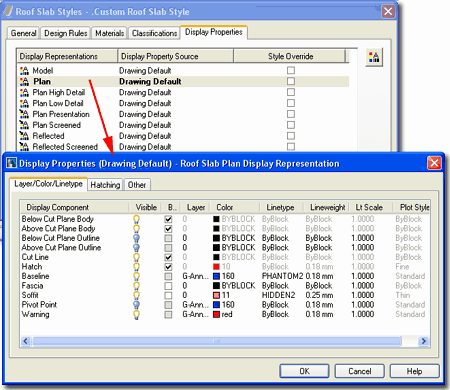
The Display Properties tab of the Roof
Slab Styles dialog box, illustrated right, provides access to the display
characteristics of the components of your Roof Slab objects; from Visibility to Cut Plane
Height overrides. This is also where you would go to have Roof Slabs change color or
Materials, for example, when you switch from one Display Configuration to another.
See the discussion on Roof Slab Display Properties below for more information on this
subject.
 Illustrated
to the left, is another way to access the Display Properties tab; select
the specific object, right click on your mouse
to invoke the object-specific pop-up menu and select Edit Object Display... Just
be aware that when you use this approach, you can actually set an Object Override as
opposed to a Style Override. Object Overrides can be extremely useful because they
allow you to add hatch patterns or change colors of any single object within a Style
Family but they can also be problematic because they lock you out from more centralized,
Style level, controls. Illustrated
to the left, is another way to access the Display Properties tab; select
the specific object, right click on your mouse
to invoke the object-specific pop-up menu and select Edit Object Display... Just
be aware that when you use this approach, you can actually set an Object Override as
opposed to a Style Override. Object Overrides can be extremely useful because they
allow you to add hatch patterns or change colors of any single object within a Style
Family but they can also be problematic because they lock you out from more centralized,
Style level, controls.
|
 |
| Roof Slab - Display
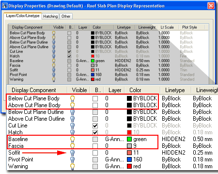
Properties - Component Layers 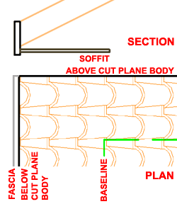 Illustrated to the right I
show how you can do some minor changes to the Plan Display
Representation of a Roof Slab Style to achieve a more
"AutoCAD-like" level of control over the Color, Linetype,
Lineweight and so on of certain Components. By removing the By
Material checkmarks from the Below and Above Cut Plane Body Display Components,
you can use the ByBlock setting to acquire the freedom to set the Color by Layer or by
manual override. Illustrated to the right I
show how you can do some minor changes to the Plan Display
Representation of a Roof Slab Style to achieve a more
"AutoCAD-like" level of control over the Color, Linetype,
Lineweight and so on of certain Components. By removing the By
Material checkmarks from the Below and Above Cut Plane Body Display Components,
you can use the ByBlock setting to acquire the freedom to set the Color by Layer or by
manual override.
By activating the Baseline Display Component and assigning
it unique display characteristics, like the "HIDDEN2" Linetype, this Component
can be used to represent edge of Walls Below as in classic Roof Plan drawings.
By following similar techniques for the Fascia, you can
lighten the display for more detailed items such as gutters and trim.
Also illustrated to the right, I show that I have turned
the Visibility of the Soffit Off because I do not want this potentially confusing line to
appear under my Baseline. |
 |
| 10Roof Slab Display Properties |
10-8 ROOFS - ROOF SLABS |
| When working with
the Display Properties of Roof Slabs you are likely to focus on the most
elementary display requirements: Plan View for Construction Documents.
I have to admit that to this day, despite all of my efforts to the contrary,
I still end up with 2D linework for my Roof Plans just as I do with Sections
and Elevations and the reason is the same: for greater control over linework
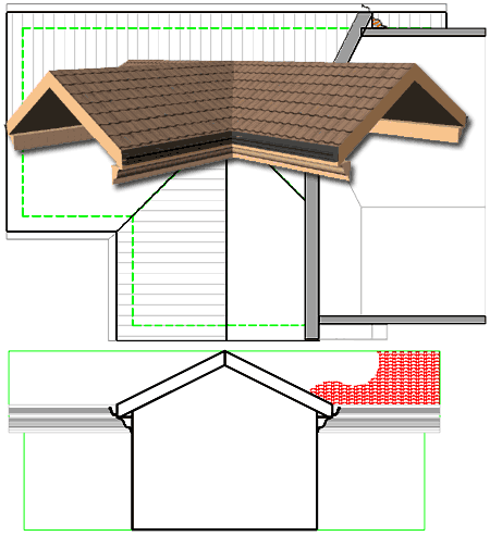
and details. Illustrated to the
right I show four views of a simple gable roof with a custom gutter and
fascia design.
For me, getting a Roof Slab to look correct in Plan View for
Construction Documents is the most important task and then I worry about the Section View.
From the Section View, I typically use the 2D Linework as a rough sketch that I
detail manually using AutoCAD tools and commands. |
 |
Roof Slabs
in Plan
| Menu |
Format> Display
Manager... |
 |
 |
| Keyboard |
DisplayManager |
| Keyboard |
DisplayProps [Attach] |
| Mouse |
Select Object, right-click,
select Edit Door Style... or Edit Window Style... or Edit Object Display... |
| Links |
Part 1 - Display - Object
Display Properties Overview - for more information on how to access the Display
Properties of this Object. |
In Plan View, you will need to think of
your Roof Slab as a 3D object that Slopes through a
planar cutting plane in order to make sense of the Above and Below Display Component
options ( assuming your roof isn't flat, of course ). By working with the Cut Plane
Height on the Other tab of the Display Properties dialog box, you can control where an
imaginary plane will cut through your Roof Slab and thereby establish which lines will be
Above and which will be Below.
The Hatch Display Component applies to the
portion of the Roof Slab Body that is sectioned by this imaginary Cut Plane and the
outline of this body cut is controlled by the Cut Line Display Component
- see illustration, lower right. If using the "By Material" option, make
sure the "Plan Hatch" Display Property is Visible on the Material Definition
Properties dialog.
For the Above and Below linework, you can use the Above
and Below Cut Plane Body and Outline Display
Components. The Body represents the 3 dimensional form and controls the Surface
Hatch Material Display so if you turn the Visibility of this Component Off, you
will also be turning the Surface Hatch Off ( a little confusing isn't it ). The
Outline represents a 2 dimensional form and does not appear to control any hatching
options. You will notice the difference in Plan View when you have Fascia edges that
are Square to steep slopes; the Body Display Components will show both the top and bottom
outlines of the fascia but the Outline will only show the top outline. You can use
both and emphasize the top face of a Roof Slab or turn the Body off to make a more simple
representation. |
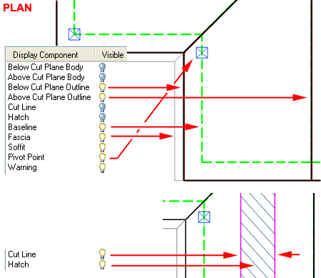 Illustrated to the right I show a slightly
modified version of the default "Medium Detail"
Display Configuration which uses the "Plan" Display
Representation for most Objects. In order to illustrate how you can use the
Baseline and Fascia Display Components, I unchecked the "By Material" option to
take direct control and set the Baseline to a Green Dashed Linetype (representing an
outline of Walls below) and used a thin Gray Color for the Gutter. These types of
settings can also be controlled through the Material Definition but sometimes it's faster
to just ignore or bypass the Materials. |
| Roof
Slab Above and Below the Cutting Plane
 Before you proceed to make adjustments in the display of the Above and Below
Cut Plane Components, you should decide on whether you want to work with the Body or
Outline Components ( mixing them is another possibility ) - see comments above for a
description of what these Display Components do. Before you proceed to make adjustments in the display of the Above and Below
Cut Plane Components, you should decide on whether you want to work with the Body or
Outline Components ( mixing them is another possibility ) - see comments above for a
description of what these Display Components do.
The Plan View Representation for Roof Slabs is affected by
the Global Cut Plane setting as set on the current Display Configuration. In most
drawings this value is set to 3'-6" Imperial or 1400mm Metric by default and thus
most Roof Slabs would be above this height. Logic would suggest that the lines of a
Roof Slab should thus be dashed by default given that they are all Above the Cut Plane but
that's not what you will find in the ADT template files.
If you take a look at the Display Components of a Roof Slab
for most of the Display Representations, you will find that the Above and Below Cut Plane
Body Display Components are controlled "By Material" so you have to explore the
current Material Definition's Display Properties in order to see what's really going on
for the Above and Below Cut Plane Body linework. For the Above and Below Cut Plane
Outlines, there is no "By Material" option so working with these Components can
prove to be easier since you don't need to worry about how a Material Definition affects
the linework.
If you take a look at the Material Display
Properties for the current Roof Slab Style, you will find that it has a "3D
Body" Display Component that correlates to
the Above and Below Cut Plane Body Display Components of the Roof Slab Style Display
Properties. Since one Material Display Component controls two different Display Components
of the Roof Slab, you will need to deactivate one if you want to differentiate the Above
and Below Body linework. In other words, don't use "By Material" for
either the "Below Cut Plan Body" or the "Above Cut Plane Body" Display
Component.
In the illustration to the right I show two Plan View
scenarios involving the Above and Below Cut Plane Display Components. For both, I
have used the "Override Display Configuration Cut Plane" option on the Other tab
to control the height between Above and Below linework. |
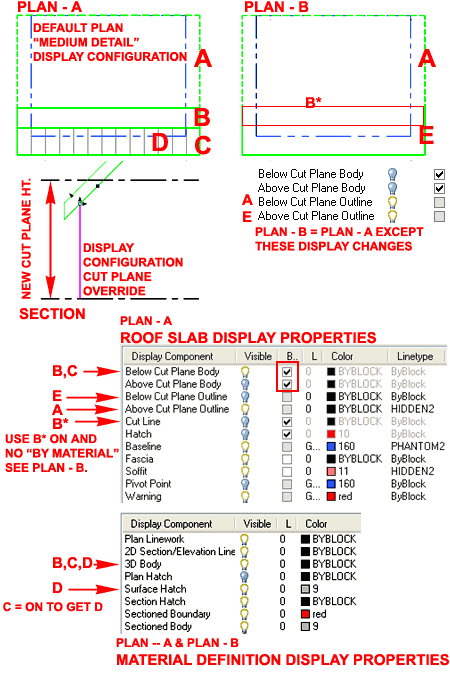 Plan - A uses the Above
Cut Plane Outline ( A ) Display Component to create a simple dashed outline. This
Display Component uses no Materials so you can set the desired linework appearance right
on the Display Properties dialog as illustrated by the "Hidden2" Linetype
setting. The Below Cut Plane Body ( C ) has been displayed and uses a Material Definition.
On the Display Properties dialog for the current Roof Slab Material Definition, I show
that the 3D Body ( B,C
) Display Component controls the appearance of this linework but since it represents the
"body", you automatically get the Cut Line regardless of how this Display
Component has been set on the Roof Slab Display Properties dialog. The Hatch is
controlled by the Surface Hatch ( D
) Display Component on the Material Definition's Display Properties and is part of the 3D
Body Display Component.
Plan - B
uses the same general settings as Plan - A, except that the Below Cut Plane Body has been
replaced by the Below Cut Plane Outline ( E ) Display Component. This produces a cleaner
outline with no option for a Surface Hatch. If desired, you can activate the display
of the Cut Line (
B* ) by turning
this Display Component On and deactivating the "By
Material" setting. |
| Roof Slab Hatch in Plan
For setting and controlling Hatch Patterns on sloped Roof
Slabs, you must use Material Definitions because the Hatch Display Component is for Plan
View only; as in a sectional plan view. The biggest problem with Surface Hatching
Roof Slabs in Plan View is that you cannot control it like you can on 2D Elevations and
Sections so you basically have to accept that the patterns will fill the entire surface
area of a Roof Slab ( not very attractive when using Spanish tiles or other highly ornate
patterns ). The only control you have over the span of Surface Hatch Patterns is the
Cut Plane and the Roof Slab Above and Below Cut Plane Body Display Components. If
you attempt to use these Display Components to control your Surface Hatch, however, all
you get is a linear cut off that doesn't read like a fade-off and you will see the line or
lines of the cut plane since they are displayed by the Body Components.
In the illustration right, I show that for the current Roof
Slab Style, I have set a custom Material Definition that I named
"Hatch.Lines". On the Material Definition
Properties dialog box for this custom Material Definition, I
show that for the current Display Representation, "General
Medium Detail", I have accessed the Style Override Display
Properties dialog box to confirm that the Surface Hatch
Display Component is Visible on the Layer/Color/Linetype
tab. On the same dialog box, under the Hatching tab, I
also show that I have set a simple 'user single" Pattern
for the Surface Hatch Display Component and set the Angle to 90 degrees relative to the
Object. And finally, on the Other tab of the same dialog box, I
show that I have confirmed that the Surface Hatch Placement is set to
display for Top.
Note:
The Surface Hatch Display Component will not display if you have the 3D Body Display
Component turned Off. |
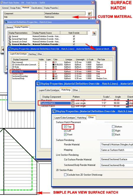 |
| Slab Hatch in Section
|
For
2D Sections of Roof Slab Objects, you can use the Material Definition Style's
Display Representation Properties to work on the Section Hatch
Display Component. For this Display Component, you can use just about any Hatch
Pattern and Scale but I did find one pattern that did not work: Solid. This appears
to be a bug in the software but you can work around this problem by using the 2D
Section/Elevation Styles to control how you want the Shrinkwrap Hatch
(turned Off by default) - see Part 15 - Sections for more information on this topic. |
| |
|
| 11Roof Slabs - Customizing and Tricks |
11-8 ROOFS - ROOF SLABS |
| Mixing Roofs and Roof Slabs Though it may seem obvious when highlighted, the illustration to the
right did catch me off guard when cranking out some design work on a recent project where
I used Roofs and Roof Slabs, where appropriate, for various solutions.
The Thickness Value for Roofs
is measured relative to the "Edge Cut" while
the A - Thickness Value for Roof Slabs is always true
regardless of the "Edge Cut". In other words, Roofs measure the fascia
height while Roof Slabs measure the rafter depth. It's quite crazy isn't it.
If you want to mix the two Roof Styles and match the
thickness as well as the fascia heights, you'll have to do a little trigonometry.
|
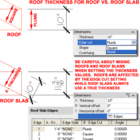 |
Using Mass Groups to create Roof Groups
| Links |
Working on
Complicated Roof Designs - for a lengthy explanation and example of how to work with
Mass Groups to create a single roof group out of many roofs and slabs. |
| |
Mass Groups - for the whole
story on using Mass Groups, Mass Elements and Boolean operators. Architectural Desktop 3
Pre-design eGuide. |
If you tend to mix different objects for your roof
solutions, such as Roofs and Roof Slabs, you may
discover that there are some unpleasant aspects of having disjointed objects; ideally a
Roof would be composed of Roof Slabs while remaining one Roof object.
Another unfortunate aspect of using Roof objects is that
they are very limited in editing options and you cannot, for example, use Boolean
operators on them to create skylights or other openings.
Illustrated to the right I show the process in which you
can use a Mass Group from the Concept pull-down menu ( Architectural Desktop 4
Pre-design eGuide ) to group all selected ADT objects into one cohesive group
object. One of the greater benefits of using this technique is that, as illustrated
in steps 3 and 4, you can introduce other ADT objects, such as Mass Elements, and create
Boolean Subtractions. I have used this technique a lot to create openings for 2nd
story Walls on multi-story buildings where the 1st floor has a wrap-around roof.
There are some drawbacks to this technique as well such as
not having the ability to differentiate colors for Soffit and Fascia elements and having
to manage more layers but overall I find this a valuable option for design solutions.
|
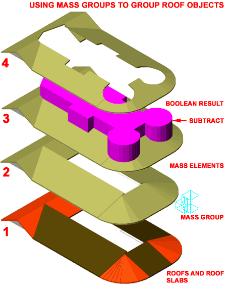 |
| 12Roof Slab Edge Styles |
12-8 ROOFS - ROOF SLABS |
Style Manager - Roof Slab Edges
| Alt.Menu |
Design> Roof
Slabs> Roof Slab Edge Styles... |
 |
 |
| Keyboard |
RoofSlabEdgeStyle |
| Links |
Roof Slab Styles - Defaults tab
- where they are set in the Roof Slab Styles dialog box. |
For Roof Slab Edges Styles,
you can use the Style Manager to load, modify, delete and create new Roof
Slab Edge Styles.
Since Roof Slab Edge Styles are rather simple and don't
have Display Property settings, starting from Scratch when making a new one is as viable
as using the Copy/Paste option that I recommend for most other Object Styles.
Assigning Materials is probably the biggest obstacle you will have to deal with when
working with the Roof Slab Edge Styles dialog box.
Illustrated to the right, I show the process of creating a New
Roof Slab Edge Style that I have Named ".custom ogee gutter".
By double-clicking on this new style, you will invoke the Roof
Slab Edge Styles dialog box - as illustrated.
The General tab provides access to the Name
and Description fields for a Style; plus access to the attachment of
Notes but no Property Sets since these will be attached to Roof Slabs.
I used the name ".custom ogee gutter" to
demonstrate how to create a simple Roof Slab Edge Style that creates the look of a
standard gutter. You can expand on this information to create extremely
sophisticated Soffit and Fascia design options. |
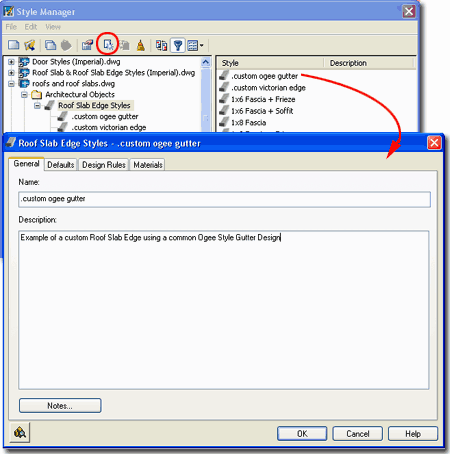 |
| Roof Slab
Edge Styles - Defaults tab On the Defaults
tab of the Roof Slab Edge Styles dialog box, you can set an overhang
distance, a plumb or square cut and any angle for the cut. Be
aware that these settings only apply to Fascias and only when you
pre-assign a Roof Slab Edge Style to a Roof Slab Style; this can only be done as an Icon
Property on the Tool Palettes. When Adding Roof Slab Edge Styles to a Roof
Slab that has already been created, these settings will be ignored but can be set as part
of the Roof Slab's Edge Settings. If this sounds like gibberish, it does have an
element of that since this is more of a legacy option that made more sense in earlier
releases of ADT.
A - Overhang - this will set an Edge Slab
Style overhang distance measured from the pivot point out. If you specify the actual
Overhang value you want on a particular Roof Slab Style here, you can use it to control
the Overhang of a Roof Slab Style by pre-assigning this Edge Slab Style as a Property on
the Tool Palette.
B - Orientation - a drop-down list
offering a Plumb or Square rafter cut on the tail ends. Plumb will give you a cut
perpendicular to the ground ( or parallel to the wall ). Square will give you a cut
perpendicular to the rafter slope. See comments for Overhang.
C - Angle - use this value to create any
angle cut you want. These angles work in conjunction with the Orientation so you can
create a 45 degree cut off of a Plumb cut. You can also use positive or negative
degrees where negative degrees cut the rafters back on the bottom. Positive degrees
cut the rafters back at the top. See comments for Overhang. |
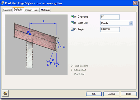 |
Roof
Slab Edge Styles - Design Rules tab
| Links |
Profiles - for how to create Profiles |
The Design Rules tab of the Roof
Slab Edge Styles dialog box holds all of the settings that create the amazing
Fascia and Soffit results. You can even be creative about the terms Fascia and
Soffit and how they actually apply to your Roof Slab Edges. You can, for example,
make a Fascia Profile that includes the Soffit should that be a desirable option.
Fascia - on/off checkbox. The the
Display of this option can also be turned on or off on the Display
Properties Layer/Color/Linetype tab of the Roof Slab Style dialog box.
Profile
- drop-down list for selection of any currently loaded Profiles. Though you
can use any profile you will want one designed for the right task with an appropriate
Insertion Point. See discussion below.
A - Auto-Adjust to Edge Height - check box
(on/off). If checked, the size of your Fascia Profile will automatically be
determined by the Roof Slab Thickness as determined by a Plumb or Square cut. The
scale maintains aspect ratio so your fascia profile grows or shrinks in both X and Y
directions simultaneously. This is a nice option but should not be used for Profiles
that have been designed to match actual construction dimensions ( like gutters ).
Soffit - on/off checkbox. The the Display
of this option can also be turned on or off on the Display
Properties Layer/Color/Linetype tab of the Roof Slab Style dialog box.
Profile
- drop-down list for selection of any currently loaded Profiles. Though you
can use any profile you will want one designed for the right task with an appropriate
Insertion Point. See discussion below.
B - Auto-Adjust to Edge Overhang Depth - check
box (on/off). If checked, the size of your Soffit Profile will automatically be
determined by a number of various controls; primarily the distance from the Roof Slab
Baseline to the Fascia. You can make changes to the size and position of the Soffit
Profile by working with D - Horizontal Offset from Roof Slab Baseline and
F - "X" Direction. The scale maintains aspect ratio so your
Soffit profile grows or shrinks in both X and Y directions simultaneously.
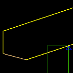 C - Angle - pivots the Soffit Profile or line ( if
you use *NONE*) up or down from the outer bottom corner of the Roof Slab. This is an
interesting option for a simple rafter cut, try something like -15 degrees with a *NONE*
Soffit Profile. C - Angle - pivots the Soffit Profile or line ( if
you use *NONE*) up or down from the outer bottom corner of the Roof Slab. This is an
interesting option for a simple rafter cut, try something like -15 degrees with a *NONE*
Soffit Profile.
D - Horizontal Offset from Roof Slab Baseline
- this will move the Soffit Profile out and away from the Roof Slab Baseline or in ( by
using a negative number ). You can use this to compensate for a Baseline that isn't
on the outside edge of a Wall, for example. This will affect the Soffit Profile
scalar size if Auto-Adjust is on. |
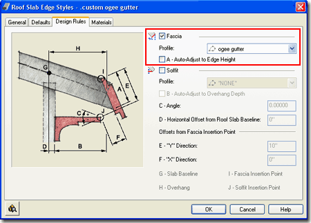
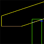 E - "Y" Direction - this value allows you
to position a Soffit Profile vertically based on a distance from the outer top corner of a
Roof Slab ( see E below, right ). Used
with a Soffit Profile of *NONE* can create a nice cut on the bottom of your rafters. E - "Y" Direction - this value allows you
to position a Soffit Profile vertically based on a distance from the outer top corner of a
Roof Slab ( see E below, right ). Used
with a Soffit Profile of *NONE* can create a nice cut on the bottom of your rafters.
F - "X" Direction -
this value allows you to move the Soffit Profile horizontally with respect to the outer
bottom corner of the Roof Slab. I don't believe that you'll see anything change if
you use the *NONE* Profile but on an actual Soffit Profile it will move it back towards
the Wall. If you have Auto-Adjust on and also work with the D - Horizontal Offset
from Roof Slab Baseline value, you can squeeze your profile into a tiny dot; i.e, you have
the ability to compress it from two side offset values. |
| Roof
Slab Edge Styles - Fascias and Soffits
Illustrated to the right I show some quick sketches of a
gutter and fascia board and a soffit trim assembly. The dialog box and values used
to create this image come from the Design Rules tab discussed above,
right.
To create your own Fascias and Soffits, you will need to
draw these items in profile or cross-section with the Pline command. The shape you
create must be contiguous and closed. The orientation illustrated must also be used;
i.e., they must face right. Use the Profile command to Define these items and use
appropriate Insertion Points ( see yellow dots, left ). The fascia object is
attached to the top of your Roof Slab so if you want a gutter or other item down a bit,
you can copy my example or simply select an insertion point above your Pline object.
The Soffit object must be a separate Profile Style.
Once created, you can attach them to your Roof Slab Style
as discussed above under the Profile drop-down lists.
In the illustration to the right, I left the custom gutter
and fascia board in a 1:1 ratio and thus made sure to have A - Auto-Adjust to Edge
Height off. For the Soffit, I wanted it to work for a variety of different
overhangs, so I set B - Auto-Adjust to Edge Overhang Depth on. This
can create unrealistic proportions but saves a lot of time. I also used the Offset from
Fascia insertion option, E - "Y" Direction, to cut the rafter
tails 6" ( 152mm) from the top.
I made the gutter solid because there's no way to easily
cap the gutters and I find that open gutters are more noticeable than solid ones. It
all depends on what you plan on doing with your efforts; render or cut detailed sections. |
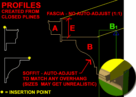 |
| Roof
Slab Edge Styles - Materials tab
As with the Material subject under other Object Styles, I
leave this massive subject to a different part of this and other guides but what is a bit
unusual about the Materials for Roof Slab Edge Styles is that these are essentially
sub-materials that are actually applied inside the Display Properties of Roof Slabs
Styles. To make matters worse, my tests on the use of Materials for Linework in Plan
found that the Materials don't work to control this Property so if you want to change the
Plan Linework Color set it directly as a Fascia or Soffit Property on the Roof Slab Style
Display Properties dialog instead of the Roof Slab Edge Style's Material.
Illustrated to the right I show that Roof Slab Edge Styles
will offer two predefined Components ( Fascia and Soffit ) and that the Material
Definition Name will be set to "Standard" when you create a Style from
scratch. If you have imported any of the Architectural Desktop Roof Slab Styles
from the Object Style Library, you should find that you will be able to use the Material
Definitions that come with those objects - as illustrated to the right where I am
selecting Paint for my example gutter.
|
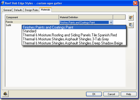 |
| 13Roof Slab Edges - Customizing and Tricks |
13-8 ROOFS - ROOF SLABS |
| Downspouts
You can use a Structural Member Style
for downspouts. First, create a Structural Member Style that meets the
specifications for your downspout. Second, draw a profile of the
downspout path in Elevation View as illustrated to the right. Third,
use the "ColumnConvert" command to convert the Polyline into a
Structural Member. Fourth, on the Properties Palette set the Style to
your custom downspout Structural Member Style, set the Member Type to
"Column" and adjust the Justify setting as required.
You may find some minor graphical issues in
the Plan View Display Representations but those can be corrected fairly
easily. The most important change involves setting the Cut Plane
Height to the top portion of the downspout; i.e., override the current
display cut plane height. Be sure to read the full article on this
trick for more information. |
 |


 In the first
release of Architectural Desktop, the Roof Object was the only solution
we had for creating roofs but it soon became evident that roofs can easily become far more
complex than any routine can handle so a new Object was introduced in ADT 3.0 called a Roof
Slab. Though the Roof Slab offers greater flexibility in design options, it
can also be more difficult to work with and thus I continue to recommend that designers
start with the Roof Object whenever possible and then convert it to a Roof Slab Object if
that option is required. Of course there are times when it is obvious that using the
Roof Slab Object is the right choice from the beginning, such as flat roofs and thus you
should simply become versed in both types and pick the best option based on experience.

 The Roof
Slab Object is nearly identical to the Slab Object and thus you may soon be
wishing for more features for such things as material components, framing options and
better construction tools for intersections, skylights and dormers. One of the
primary problems with the Roof Slab Object is that it, like the Roof Object, measures the
Overhang distance from the Baseline (a perimeter edge at the planar justification point)
or Pivot Point so if you draw a Roof Slab along the inside face of stud or structure, you
have to add the the thickness of the Wall. Unlike the Roof Object, however, when you
use the RoofSlabConvert option, you can specify where you want the Baseline/Pivot Point
relative to the Wall. After creation, there are several options for working
with the Pivot Point and Baseline locations but the Overhang value is always measured from
the Baseline.


 Edge
cut - use this drop-down list to choose between Square and Plumb
fascia cuts. A Square cut is perpendicular to the slope of the roof while a Plumb
cut is always perpendicular to the ground and offers a more common cut when mounting
gutters along the edge. See comments under Thickness for how this affects the true
thickness of the roof object.
 Illustrated to the right I show a simple scenario using the default approach
to Adding a Roof Object by OSNAPping along the exterior Wall Endpoints
(or Intersection, etc. but I find Endpoints most suitable for this task ). As
illustrated, once you have three or more points, you should begin to see a Roof Object
emerge and as you add more points, the roof will change form. When you have reached
the last point ( numbered "6" in
the illustration ), use the Enter key on the keyboard to close the Roof
Object and close the Properties Palette.


 question, otherwise you can actually lose your
Walls.

 Under
the Dimensions section of the Roof Properties Palette,
you should find that you have access to all of the changeable features of a Roof. In
the Roof Edges area, you should see a number of Edges
equal to the number of sides to your Roof ( in plan view ). The Edges
start with the number zero ( 0 ), so that can make it a little confusing.
For each Edge, you can make unique adjustments to the Height, Overhang,
Eave, Segments and Radius ( if it
applies ). In addition to the Edge adjustments, you can select an Edge and work with
its corresponding Face in the Roof Faces (by Edge ) area.
 To
make the task of accessing and working on individual Roof Edges easier, you can use the RoofEditEdges
command or object specific pop-up menu option. When you select a roof with this
tool, pick near the bottom fascia or along the top plate where the roof should hit a Wall.
When you select in the right location, you should notice a single line highlight as
illustrated to the right. You can select more than one edge at a time.


 There
are two ways that you can access the Display Properties of Roof Objects: one way is
through the Display Manager and the other way is Illustrated to the left - select the
specific object, right click on your mouse to invoke the
object-specific pop-up menu and select Edit Object Display...

 As with the other Objects in ADT, I feel that the
Plan View is the most important to focus on. With Roofs and Roof Slabs, however, it
can probably be argued that Elevations are actually where you get the biggest return on
the investment of using these Objects because, let's face it, you can draw a roof plan
with regular AutoCAD lines a lot faster.


 The
Direct Mode method of Adding a Roof Slab assumes that you know the pitch
by the virtue of the 3rd point you pick. If you don't pick a 3rd Point in Space that
happens to be higher on the Z-axis than the 2nd point, there will be no slope
change. Using the Left or Right Direction options really make no sense for this type
of Roof Slab creation since the Directions apply to the command-line "Ortho
Close" option and together these two options only work after the second point has
been selected ( not the third or more points). In other words, you can't select the
third point to establish the Slope so use this whole combination of options only when you
want no Slope Roof Slabs.


 Style - allows you to change the selected Roof Slab
to any other Roof Slab Style currently loaded in your drawing file.
 Pivot
Point X,
Y and Z - a very important modification
option because it allows you to move the point at which your Roof Slab
pivots with respect to any change in the Slope. Suppose, for example,
that you have calculated the ridge of your roof from a particular Wall but
you are uncertain about where the fascia should end up - you can move the
Pivot Point to the calculated ridge and set the slope from there to assist
you in finding out where the fascia will actually sit. You may
also find it necessary to move the Pivot Point to match how you expect your
Rafters to be seated on a Plate.
Pivot
Point X,
Y and Z - a very important modification
option because it allows you to move the point at which your Roof Slab
pivots with respect to any change in the Slope. Suppose, for example,
that you have calculated the ridge of your roof from a particular Wall but
you are uncertain about where the fascia should end up - you can move the
Pivot Point to the calculated ridge and set the slope from there to assist
you in finding out where the fascia will actually sit. You may
also find it necessary to move the Pivot Point to match how you expect your
Rafters to be seated on a Plate.
 he Roof Slab Edit Edges tool
offers you direct access to the Edges tab of the Roof Slab Properties dialog box.
When using this tool, you need to select one or more Roof Slab Edges by picking near them
or directly on the perimeter line ( usually displayed as a blue dashed line). If you
have a rather complex Roof Slab with many edges, this is a great way to isolate just those
edges that you wish to edit so you don't have to hunt for their index number on the Roof
Slab Edges dialog box.


 Has Fixed Thickness - check this box to lock in a Roof Slab
Style's Roof thickness value so that it can't be changed except through the Style.
When you check this to fill in a value for Thickness, you will also be deactivating the A
- Thickness value field on the Properties Palette.


 Illustrated to the right I
show how you can do some minor changes to the Plan Display
Representation of a Roof Slab Style to achieve a more
"AutoCAD-like" level of control over the Color, Linetype,
Lineweight and so on of certain Components. By removing the By
Material checkmarks from the Below and Above Cut Plane Body Display Components,
you can use the ByBlock setting to acquire the freedom to set the Color by Layer or by
manual override.


 Before you proceed to make adjustments in the display of the Above and Below
Cut Plane Components, you should decide on whether you want to work with the Body or
Outline Components ( mixing them is another possibility ) - see comments above for a
description of what these Display Components do.


 C - Angle - pivots the Soffit Profile or line ( if
you use *NONE*) up or down from the outer bottom corner of the Roof Slab. This is an
interesting option for a simple rafter cut, try something like -15 degrees with a *NONE*
Soffit Profile.
 E - "Y" Direction - this value allows you
to position a Soffit Profile vertically based on a distance from the outer top corner of a
Roof Slab ( see E below, right ). Used
with a Soffit Profile of *NONE* can create a nice cut on the bottom of your rafters.

