| 1Anchors - Access |
1-23 ANCHORS |
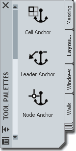
How do I get this toolbar?
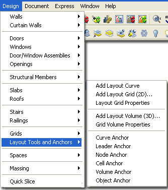
You can also acquire access to these commands from the Alternate Design pull-down
menu. From the Design pull-down menu, pick
Layout Tools and Anchors>
and cascade to their respective command options - see image below, right.Illustrated to the right is the Anchors toolbar
but I also show the Layout Tools and Grids toolbars because these are all
Objects that Anchors have been designed for.
|
 |
 |
 |
| Anchors
pull-down menu
 Anchors or anchoring is
something you have probably already worked with whether you were aware of it or not.
Many of the Objects in ADT that behave in "intelligent" ways, owe some of
their "intelligence" to anchors. The fact that Door and Window Objects
automatically "glue" themselves to Walls (and not just Walls but bases of Walls)
shows what Anchors can do for you. You can, for example, release the Wall Anchor on
a Door or Window Object to have the object as a free form in space ( I like
to refer to this as free-floating an Object). Most Anchored objects
can be released through the Release Anchor option on the Context pop-up menu; i.e., select an object, right-click on your mouse and look for the Anchors
> option ( see below right ). Anchors or anchoring is
something you have probably already worked with whether you were aware of it or not.
Many of the Objects in ADT that behave in "intelligent" ways, owe some of
their "intelligence" to anchors. The fact that Door and Window Objects
automatically "glue" themselves to Walls (and not just Walls but bases of Walls)
shows what Anchors can do for you. You can, for example, release the Wall Anchor on
a Door or Window Object to have the object as a free form in space ( I like
to refer to this as free-floating an Object). Most Anchored objects
can be released through the Release Anchor option on the Context pop-up menu; i.e., select an object, right-click on your mouse and look for the Anchors
> option ( see below right ).
Though many Objects in ADT use Anchoring as
part of their function, those Anchors are not necessarily equivalent to the
Anchor Tools and though you know, for example, that a Door has an Anchor,
you can't use any of these Anchor tools to work with it.
|
The Primary purpose for the Anchor Tools is to
work with the Layout Tools ( including, of course, Column and Ceiling Grids
). This means that if you want to utilize the Anchor tools to their
greatest potential, you really need to understand how to work with the
Layout Tools and I recommend that you focus specifically on the Layout
Curve.
Below is the command line read-out for "Anchor":
Command: Anchor
Anchor [CEll/CUrve/Leader/Node/Volume/Identify/Release]: |
| Anchors
- menus and dialog boxes
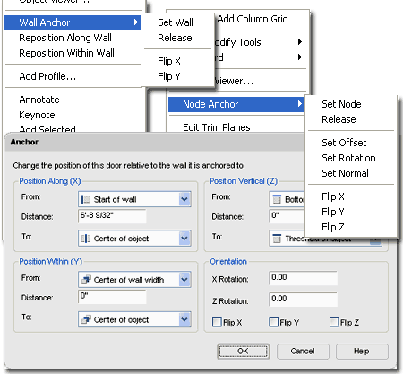
Anchors, anchors, anchors everywhere. Illustrated to the right I show
three different examples of where you are likely to encounter Anchors.
As discussed above, not all Anchors are equal and you should not let me
confuse you about the Anchor Tools and Anchors in general but I do want to
make you aware that they are virtually ubiquitous in ADT. Having a
solid understanding of anchoring whether it is how a Door sits in a Wall or
how a Column can be fixed to a Column Grid Node is a big part of mastering
Architectural Desktop.
Most users of this program tend to work
graphically and often avoid venturing into dialog boxes such as the Anchor
dialog illustrated to the right. The problem with this approach and
attitude is that some technical problems just can't be solved effectively by
working with Grips or or other graphical devices. In the case of a
Door or Window in a Curved Wall, it can be incredibly difficult to
accurately position these Objects along a Curve. Students often get
frustrated in my classes as they observe an Object bounce to one side or
another but never right to the location they want; even when using OSNAPS.
If you Select an Object that is Anchored to something like a Wall, you
should find the Anchor dialog on the Properties Palette for the Anchored
Object. By working with the various Position settings on the Anchors
dialog, you can take extremely accurate control over where Objects reside. |
 |
| 2Working with the Curve Anchor |
2-23 ANCHORS |
| Curve
Anchors
The Curve Anchor is arguably the
most powerful in this suite of Tools because it offers the option to
Anchor just about any ADT Object to nearly every other type of Object; from
Lines, Arcs, Circles and Splines to Doors, Walls and Grids. I haven't
tested all of the various Object Types in ADT but most Style Based Objects
can be Anchored with this Tool. Multi-View Blocks can be Anchored but
regular AutoCAD-like Blocks cannot. In fact, no AutoCAD-based Object
can be Anchored but a clever user might simply convert a Regular AutoCAD
Block into a Multi-View Block in order to Anchor it ( if needed ).
When using this tool, you may find that some
Objects get spun around a bit and will require adjustments to their
Orientation. This is particularly obvious with Structural Members
whose Normals are not the same as that of other Objects. In fact, I
cannot recall if I ever figured out how to reorient Structural Members when
Anchored with the Curve Anchor - see Layout Curves for a better option to
avoid this problem. For other Objects, reorientation should be a
simple matter of working with the X, Y and Z Positions or Rotating.
Usually you can access the Anchor dialog via the Properties Palette to make
changes after Anchoring.
Note:
Though the prospect of using this tool to Fix the problem with Tags that
don't follow their parent Object seems quite plausible, the action destroys
the original anchoring and thus dissociates the Property Set Data that is
fundamental to using Tags in Schedules. I state this with
disappointment because I tried it with Door and Window Tags and was quite
pleased to find how the Tags moved with my Objects but then discovered that
I had lost my Data.
|
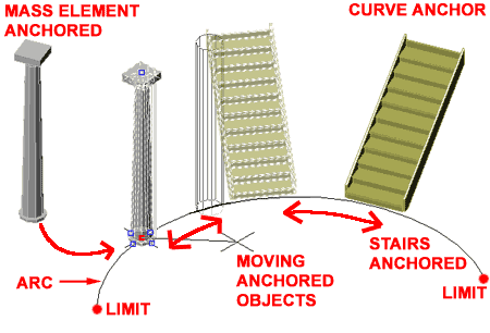
In the illustration above, I show a common
AutoCAD Arc used as the subject of working with the Curve Anchor.
To Anchor an object to a Curve, pick the Curve
Anchor button, type AT on the command line, select your
object to be anchored and then select your Curve ( Line, Pline,
Arc, Door, Window, Wall, Stair, Roof Slab and so on ).
Command:_AecCurveAnchor
Curve anchor [ATtach object/Set curve/X position/Y position/Z position/Rotation/set
ANchored end]: AT
Select object to be anchored: ( pick column or any other object )
Select curve to anchor to: ( pick on curve )
Once you have anchored one
object to another, they will behave much like a Door or Window in a Wall.
In the illustration above, for
example, I show that you can Move these Anchored objects and they stay
glued to the Curve within the Curve's limits. I also illustrate, to the right, that
you can use Grips ( see column ), but be careful because
on many objects, using Grip Stretch actually moves the Anchor relationship. You can
use the Grip Move option to be safe. |
| Curve Anchor
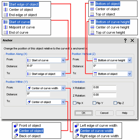
dialog Illustrated to the right I
show the Anchor dialog that you will see when using the Curve Anchor
option. Of all the Anchor dialog boxes, this one holds the greatest
number of options and settings and is the one that you are most likely to
encounter when working with other Objects in ADT; such as Doors, Windows,
Walls and so on.
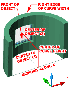 Each of the three Position sections
offer three similar position controls. The "From" drop-down
list relates to the target of the Anchor while the "To" drop-down
list relates the Object being Anchored. By working with the Distance
value field, you can be very specific about where an Object is positioned
relative to itself and the target. As you can see from the
illustration to the right, each drop-down list offers position options that
relate to extreme edges or centers of Objects and Anchor Targets. Each of the three Position sections
offer three similar position controls. The "From" drop-down
list relates to the target of the Anchor while the "To" drop-down
list relates the Object being Anchored. By working with the Distance
value field, you can be very specific about where an Object is positioned
relative to itself and the target. As you can see from the
illustration to the right, each drop-down list offers position options that
relate to extreme edges or centers of Objects and Anchor Targets.
The Orientation section offers Rotation and
Flip ( Mirror ) options that can be used to affect the Object
relative to the Anchor Target. In some cases when Objects are
Anchored, they default into a position and rotation that is different than what you want or
expect. This is particularly true of Structural Members.
|
Notice that you can Rotate Anchored Objects
through the X-axis and Z-axis but not the Y-axis which can
prove to be a bit irritating at times and I don't have any work-around
solutions for this other than modifying the Object being Anchored but in the
case of Windows, for example, that's really not an option. Fortunately
Windows are usually parallel to Walls. |
| 3Working with the Leader Anchor |
3-23 ANCHORS |
| Leader
Anchors
Leader Anchors offer the option to Anchor an Object to a
Node with a
connecting line or "leader". If you combine this feature
with the power of the
Layout Curve which can Add Anchor Nodes to just about
any Object, you should be able to come up with some pretty interesting
solutions for common drafting problems.
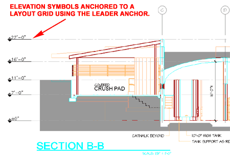
Illustrated to the right I show how I often
Anchor my Elevation Datum Points to a
Column or Layout Grid that I use with
2D Linked Sections and Elevations. The Leader Anchor offers options
for controlling the length and position of the leader tail so you can even
move it out of direct alignment if space is tight. |
 |
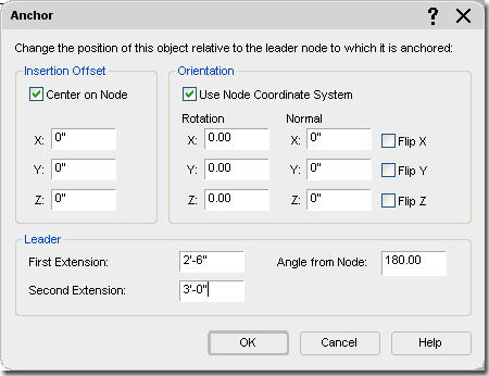
| Leader Anchor
dialog
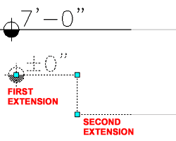 Illustrated to the right I
show the Anchor dialog that you will see when using the Leader Anchor
option. Unlike any of the other Anchor dialog boxes, this one offers
the option to set First and Second Extension values for the Leader. Illustrated to the right I
show the Anchor dialog that you will see when using the Leader Anchor
option. Unlike any of the other Anchor dialog boxes, this one offers
the option to set First and Second Extension values for the Leader.
Illustrated to the left I show an example of
an Elevation Datum with First and Second Extension Values. A straight
leader has no Second Extension value but a bent one has two values as
illustrated left and on the dialog, right.
Insertion Offset
Whether or not this checkbox is on, seems to make no difference in this
case. Working with the X, Y and Z values will allow you to move the
start point of a leader line out and away from a Node.
Orientation
For most Plan (top) work with Grids and Anchored
Objects, you probably will not find the need to work with other coordinate
systems or unique Normals. Rotation about each of the three axis
points provides the option to control the position of the Object being
Anchored and should not be confused with the Angle from Node value that
controls the Leader. |
For 3D Volume Grids or Grids that have been
Added under non-World UCS icon rotations, you may find the need to uncheck
the "Use Node Coordinate System" so the Object being Anchored will align
properly with the Grid. Working with Normals ( use 1" or -1" ) offers
another method for rotating. |
| 4Working with the Node Anchor |
4-23 ANCHORS |
| Node
Anchors
Node Anchors are arguably
the easiest Anchor tools to understand because they work on a basic
principal of connecting the insertion point of an Object to a Node. If
you don't have a Node, this tool will not work. The Column Structural
Members uses this form of Anchoring as its default when Added automatically
on the Column Grid Properties Palette. Ceiling Fixtures also use this
form of Anchoring automatically when you drag them in and Select a point
near a Node to Anchor to.
There are three choices for how you can use the Node Anchor
to Attach your Object(s): Attach object, Set node and Copy to each node.
Attach object - this one should be easy to
understand because it says exactly what it does. You select your object to be Attached and then select the Node on your Layout Tool
that you want it Attached to. If you don't have the Node Display
Component Visible, you can Select near an intersection. |
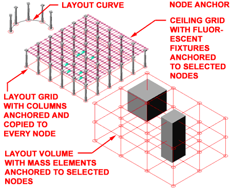
Set node - use
this option to Move or Transfer an Anchoted Object from one Layout or Grid
tool to another.
Copy to each node - this is
just like the Attach Object but with greater impact. As the command states, you will
not only Attach a selected object but also copy and attach it to all Nodes on the Layout
Tool.
Command: _AecNodeAnchor
Node anchor [Attach object/Set node/Copy to each node]: |
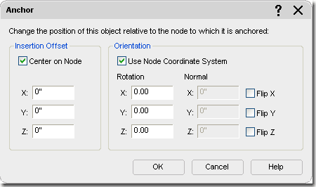
| Node Anchor
dialog Illustrated to the right I
show the Anchor dialog that you will see when using the Node Anchor
option. Since anchoring to Nodes is pretty straight forward, so too
are the Anchor options. With this form of Anchoring, you basically
have a connection between an Object and a Node. Though this method
defaults to the Object's Node or Insertion Point, you can reposition it with
the X, Y and Z Insertion Offset value fields.
For Structural Members and Ceiling Fixtures,
you may find that you will need to work with the Rotation angles ( Z-axis )
on a frequent basis since you cannot use the Rotate command to rotate
Anchored Objects.
If you need more options for positioning,
take a look at the Curve Anchor discussed above. |
 |
| Structural Members and Node Anchors
 When
using Anchors and Structural Members, you may find that some actions result
in reorientation of the Member. This problem has to do with the
fact that Structural Members have a different Entity Coordinate System (ECS) than other
ADT objects. The result is that the Normals match up and you see the ECS match the
UCS. When
using Anchors and Structural Members, you may find that some actions result
in reorientation of the Member. This problem has to do with the
fact that Structural Members have a different Entity Coordinate System (ECS) than other
ADT objects. The result is that the Normals match up and you see the ECS match the
UCS.
|
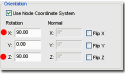
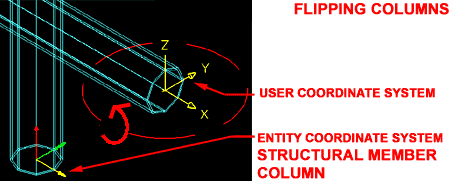 To fix a flipped Column,
for example, you have to change the Rotation
values on the Anchor dialog box. You can set X = 90
and Z = 90 or leave X and Z at 0 and set Y = -90 or 270 degrees. |
| 5Working with the Cell Anchor |
5-23 ANCHORS |
| Cell
Anchors
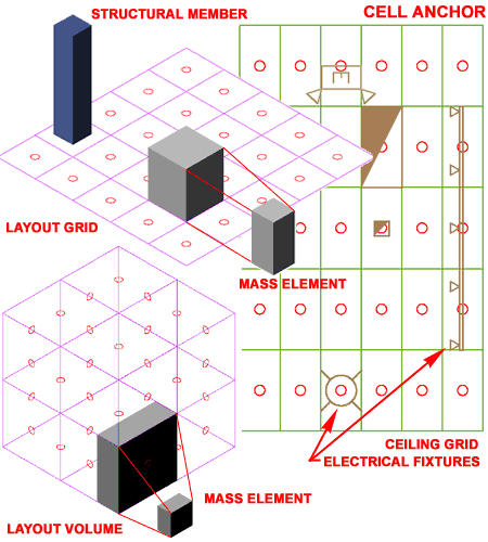
The Cell Anchor will often resize Anchored Objects automatically to match
two of the cell dimensions. The scaling effect can be changed by
working with the Properties Palette and by unchecking the "Apply Resize"
option on the Anchor dialog.
|
 |
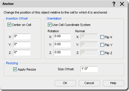
| Cell Anchor
dialog Illustrated to the right I
show the Anchor dialog that you will see when using the Cell Anchor option.
Under the Resizing section, I show that the Apply Resize checkbox has been
set which occurs by default when using the Cell Anchor tool. I also
show a "Size Offset" value which can be used to increase the resizing of the
Anchored Object by an additional factor. A Mass Element, for example,
will be resized to match the length and height of a Cell but with the Size
Offset, you can increase that size along the length and height; i.e., it
actually grows by twice the Offset amount just as a Rectangle increases with
the Offset command.
The Orientation Section is particularly
useful when dealing with Structural Members because the always lay flat when
you Anchor them to Cells. By setting the X and Z Rotation value to 90
degrees, for example, you can get a column to stand up on end once again. |
 |
| 6Working with the Volume Anchor |
6-23 ANCHORS |
| Volume
Anchors
Volume Anchors are the most specific
Anchors in the set of Anchor Tools because they only work with 3D Volume
Grids. To me, the only reason to work with this grid type is for
Massing Studies and thus it seems appropriate to use Massing Objects as
well.
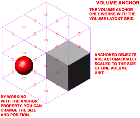
Objects that are Anchored to a Volume Grid
with the Volume Anchor will automatically be "Resized" to match the extents
of one Volume Unit ( X, Y and Z ). Mass Elements, for example, will
expand in all directions to match the dimensions of the X, Y and Z
proportions. Some Objects, like Structural Members, only expand in the
one direction that is free to become longer or shorter.
Anchored Objects can be Moved or Copied freely within a single Volume
Grid and will automatically Anchor to the next logical Anchor Position. |
 |
| Volume Anchor
dialog Illustrated to the right I
show the Anchor dialog that you will see when using the Volume
Anchor option. This Anchor dialog is identical to that used for
Cell Anchors. Keep in mind that thought this dialog is the same for
the 2D Grid, some setting apply to three dimensions. The Resize and
Size Offset options, for example, affect all three dimensions of Mass
Elements. See comments under Cell
Anchors for more information. |
 |
|
7Working with the
Object Anchor |
7-23 ANCHORS |
|
Object Anchors
The Object Anchor tool was first
introduced in ADT 2005 and is not listed as one of the Anchor options on the
Anchor command-line list. As a concept the
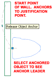 option
to Anchor any Object to any other Object is a fantastic feature and one that
I highly desire but the Object Anchor may leave you a bit disappointed
because of some interesting limitation in ADT. option
to Anchor any Object to any other Object is a fantastic feature and one that
I highly desire but the Object Anchor may leave you a bit disappointed
because of some interesting limitation in ADT.
Whatever you do, be sure to not use
this tool on Objects that are already Anchored such as Doors and Windows
because changing Anchor types removes the existing Anchor; i.e., Doors will
pop out of Walls, for example.
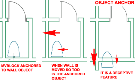
In the illustration to the right I show you
can use the Object Anchor to establish a connection between an MvBlock, such
as a Toilet, and an adjacent Wall Object. Though this can prove to be
quite useful on some projects where changes are constant, just be sure to
understand how this Anchor works. |
When the toilet MvBlock is Anchored to the
adjacent Wall Object, the Insertion point of the Toilet is used as one
reference point while only one Endpoint of a Wall Object can be used as the
other reference point. The start point of Wall Objects will be used
for the reference Anchor location but it is often difficult to remember
which end of a Wall was drawn first.
Only Architectural Desktop
Objects can be used with this tool so you cannot, for example, Anchor common
Mtext Objects to other Objects. |
|
8Modifying Anchors |
8-23 ANCHORS |
| Releasing Anchored Objects
The Release Anchor option does exactly what it states: releases an anchored
Object. In many cases this
is a simple operation with little to no consequences but try it on a Door or Window and
you lose the opening in the Wall.
|
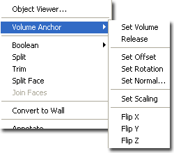 Illustrated
to the left I show one of the numerous Context menus for an Anchored Object.
Depending on the type of Anchor, you should find different options on the
cascading menu. Door and Windows, for example, only offer four Anchor
options. Illustrated
to the left I show one of the numerous Context menus for an Anchored Object.
Depending on the type of Anchor, you should find different options on the
cascading menu. Door and Windows, for example, only offer four Anchor
options.
Note:
If you want a free Door or Window, simply hit an extra return when you are Adding them and
you will be able to place them without any Anchors. |
| Positioning Anchored Objects
The Offset Anchor option is basically
another term for Move. The difference between this option and Moving
an Object is that in this case, the original Anchor position is kept.
|
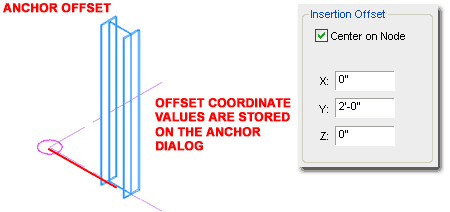
After choosing this option, you will be queried
to specify a second point relative the Object's Anchor source. This
second point move the Object relative to the Anchor source. The Offset
distance is recorded on the Anchor dialog accessed via the Properties
Palette. |
|
9Anchors - Display Properties |
9-23 ANCHORS |
Anchor
Display Representations
| Menu |
Format> Display
Manager... |
 |
 |
| Keyboard |
DISPLAYMANAGER |
Though Anchors aren't physical objects that you can manipulate in ADT, they
are objects with display characteristics. I do find it interesting that once you
display your Anchors, you can actually select an object by picking on its anchor; meaning
that Anchors are actually physical objects, we just can't manipulate them.
There are four types of Anchors that you can display: Bubble,
Free ( illustrated, left ), Leader and Tag.
|
 |
|
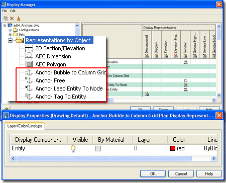
Anchor Entity
Display Component Illustrated to
the right I show the four different Anchor Types that have their own Display
Representations and some examples of where those Display Representations
might be of importance to you.
Generally the one Display Component that each
Anchor Object has is set to "ByBlock" so you may never need to
venture this deep to work this these settings.
Anchor Bubble to Column Grid - this
Display Representation allows you to control the Extension on Column Grid
Bubbles as illustrated to the right. You may want to work with
different Display Representations, such as Plan and Reflected to control the
Lineweight, Plot Style or Color when switching between these two Display
Representations.
Anchor Free - this Display
Representation is usually turned Off and as you can see from the example
image, there is a good reason for that. The one place where you might
find this feature rather handy is with Structural Members whose Normals are
not the same as that of other Objects. This fixed size icon will
display on all ADT Objects that have Anchors and are not Anchored ( Free ).
Anchor Lead Entity To Node - this
Display Representation is similar to the one for the Anchor Bubble Column
Grid. It provides the means to control the leader line between Objects
that have been Anchored with the Leader Anchor and their target.
|
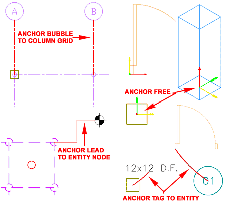 Anchor Tag To Entity - this Display
Representation is usually turned Off and you would probably find it annoying
to have it on. It draws a leader line between any Tag and the target
of the Anchor it belongs to. |
|
10Anchors - Customizing and Tricks |
10-23 ANCHORS |
| |
|


 Anchors or anchoring is
something you have probably already worked with whether you were aware of it or not.
Many of the Objects in ADT that behave in "intelligent" ways, owe some of
their "intelligence" to anchors. The fact that Door and Window Objects
automatically "glue" themselves to Walls (and not just Walls but bases of Walls)
shows what Anchors can do for you. You can, for example, release the Wall Anchor on
a Door or Window Object to have the object as a free form in space ( I like
to refer to this as free-floating an Object). Most Anchored objects
can be released through the Release Anchor option on the Context pop-up menu; i.e., select an object, right-click on your mouse and look for the Anchors
> option ( see below right ).


 Each of the three Position sections
offer three similar position controls. The "From" drop-down
list relates to the target of the Anchor while the "To" drop-down
list relates the Object being Anchored. By working with the Distance
value field, you can be very specific about where an Object is positioned
relative to itself and the target. As you can see from the
illustration to the right, each drop-down list offers position options that
relate to extreme edges or centers of Objects and Anchor Targets.

 Illustrated to the right I
show the Anchor dialog that you will see when using the Leader Anchor
option. Unlike any of the other Anchor dialog boxes, this one offers
the option to set First and Second Extension values for the Leader.


 When
using Anchors and Structural Members, you may find that some actions result
in reorientation of the Member. This problem has to do with the
fact that Structural Members have a different Entity Coordinate System (ECS) than other
ADT objects. The result is that the Normals match up and you see the ECS match the
UCS.


 option
to Anchor any Object to any other Object is a fantastic feature and one that
I highly desire but the Object Anchor may leave you a bit disappointed
because of some interesting limitation in ADT.
 Illustrated
to the left I show one of the numerous Context menus for an Anchored Object.
Depending on the type of Anchor, you should find different options on the
cascading menu. Door and Windows, for example, only offer four Anchor
options.


