 Ever since I was an
interning draftsman working on AutoCAD 1.0 at my first architectural job (
for no pay mind you ), I have hated the work involved in drawing downspouts.
I vividly recall having to redo all of my hatch patterns on elevations
whenever I discovered that I had forgotten to include downspouts or whenever
changes affected their position.
Ever since I was an
interning draftsman working on AutoCAD 1.0 at my first architectural job (
for no pay mind you ), I have hated the work involved in drawing downspouts.
I vividly recall having to redo all of my hatch patterns on elevations
whenever I discovered that I had forgotten to include downspouts or whenever
changes affected their position.
Now that I'm all grown up and no longer working for free, I find that I can often solve this irritating problem with general notes and leaders but every now and again I find that I really need to show more detailed downspout information. In the discussion below I will outline the steps I have used to create a Downspout Object in Architectural Desktop.
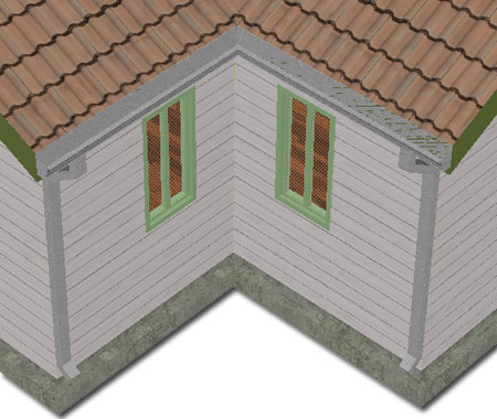
By using the Structural Member Style Wizard you can make relatively short work of making a Rectangular downspout Tube. By visiting sites like http://www.egutter.com/ you can gather the specifications required to create a realistic result.
On the first page of the three page Structural Member Style Wizard, simply locate the Steel category and look for the "Rectangular Tube" shape. This does not mean that your downspout must be steel; you can decide what you want it to be made of later.
On the second page of this Wizard, set the Section Depth, Section Width and Thickness of your downspout.
On the third and last page of this Wizard, type a Name for the Structural Member Style. The Style name will also become the name of the Structural Member Shape which is basically just another version of a Profile.
 From
an Elevation View of your building, draw an outline of your downspout using
a Polyline. You can draw this Pline along the back side, middle
or front depending on how you want the final Justification to work.
I prefer using the Back so I get Grip points right where I am most likely to
want to control this Object from.
From
an Elevation View of your building, draw an outline of your downspout using
a Polyline. You can draw this Pline along the back side, middle
or front depending on how you want the final Justification to work.
I prefer using the Back so I get Grip points right where I am most likely to
want to control this Object from.
Use the "ColumnConvert" command to convert the Polyline into a Structural Member and then use the Style drop-down list on the Properties Palette to set this value to the Downspout Style. While on the Properties Palette, confirm that the Member type is set to "Column" and that the Justify value is set to a justification that produces the most desirable results.
In my example to the right I have chosen the "Middle Right" Justify setting which will put Grip points along the Back Center of the downspout. You may need to use Middle Left to get similar results.
After trial and error runs with this technique I discovered some undesirable results in my Roof Plans so the following steps represent what I came up with as a work-around solution. The problem was that the downspout outline, or sectional cut, did not display at the Elevation Cut Plane I wanted (See Illustration "A" below left) and it showed linework I did not want.
By using the "StructuralMemberStyle" command access the Downspout Style and go to the Design Rules tab. Use the Add button to create a new Component and set the Start Shape Name to match the existing Component's Start Shape Name. This is done so the shape of the downspout does not change but keep this option in mind if you ever need to make a downspout that tapers (scuppers, for example).
Confirm that both Start Shape settings have a Relative to set to "Start" and then set the Node for the new Component to "1".
Scroll to the right and confirm that both End Shape Names match. For the first Component, set the Relative to value to "Start" with a matching Node value of "1". For the second Component, set the Relative to value to "End" and the Node value to "0".
What this work achieves is a break in the downspout. From the Top Start Position ( Node 0 ) to Node 1 one Component is used. The Component Shape remains consistent throughout the whole Style but it is now in two parts. The second part Starts at Node 1 and goes all of the way down to Node 0 Relative to the End.
 Now
that the Downspout Structural Member Style is broken up into two parts, you
can work with the Display Properties of these two parts.
Now
that the Downspout Structural Member Style is broken up into two parts, you
can work with the Display Properties of these two parts.
On the Display Properties tab of the Downspout Style, set a Style Override for the Plan Display Representation. The Override is necessary because it is highly unlikely that other Structural Members should end up looking like a downspout.
On the Layer/Color/Linetype tab of the Display Properties dialog notice that there are two "Visible Comp" Display Components which represent the cross section of the downspout. In my example to the right I show that I have turned Off the Display of All Display Components except the "Visible Comp 1 (1st Section)" because that is the very top part of the downspout and typically the only thing I want to show in Roof Plans (See illustration "B"). However, you may want to do other things such as using the second "Visible Comp 2" Display Component to create Dashed lines leading back to the Wall Below (See illustration "C").
On the "Other" tab of the Display Properties dialog, illustrated lower right, use the "Override Display Configuration Cut Plane" checkbox to free the "Cut Plane Elevation" value field. Then, set a "Cut Plane Elevation" value that will cut through the top part of the downspout. This value may change from project to project or even on the same project so remember to keep an eye on it.
To help keep these 3D downspouts in place you can use the "ObjectAnchorAttach" command or Palette tool to hook the downspout to the Roof Slab. I have tried other forms of Anchoring such as the Node Anchor to a perimeter Polyline but the work of getting the orientation right and the dismal return on this investment has led me to believe that the Object Anchor is currently the best option. I'd really prefer like to have a multipoint Anchor that kept the base to one point, the top to another and the whole downspout at a point relative to the outer edge of the building but then I must be dreaming.
Note:
Another interesting problem with downspouts is that you may have many of
them in a drawing that are basically identical so when you decide to modify
one, you would prefer to have the rest update as well. Obviously you
can use a Block or an Xref, even treat it as an Element in the Project
Navigator but you can also use the "EntRef" command to create
one Reference that you can then Copy and place as needed. If you
decide to use the "EntRef" command, be sure to flip the UCS icon to align
with the original downspout and make the Insertion Point match that of the
original. This will allow you to use the "ObjectAnchorAttach" tool
much like with the original downspout.