How do I get this toolbar?
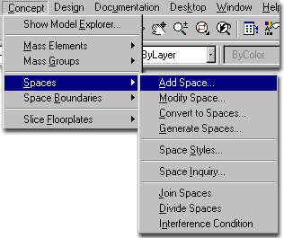
You can also acquire access to these commands from the Concept pull-down menu. From the Concept pull-down menu, pick Spaces > and cascade to their respective command options - see image below, right.

Discussion:
Space and Boundary objects can be a little confusing to understand as far as Architectural
Desktop goes. In the ADT User Guide, for example, Space Planning is described as an
"inside out" process yet by providing us with the ability to convert 2D
polylines into Spaces, it is clear that one can easily go from the outside in; i.e., from
Mass Model to Section to Spaces. In Part 11, Spaces will be discussed as an inside
out design tool. If you want information on Space Planning from the outside in,
please see the Pre-Design Guide.
In Part 11 we will look at Space tools as something you would use after having worked with Walls, Wall Tools, Doors, Windows and other primary architectural components.
Illustrated to the right is the toolbar that you would use if you were going to work with Spaces from a Pre-Design standpoint. In the Pre-Design Guide we look at Spaces as both tools in themselves for conceptual design study and as part of the process in converting Mass Elements into floor plans.

With this particular object type, I thought it wise to write a little about what Spaces are and how you might use them in your design work since they are not as obvious as Walls, Doors, Windows and Roofs. In fact, I too have broken them up into two parts: one for the Pre-Design phase of your work and another for part of the Development phase. The first thing we should make clear is that like many of ADT's objects, you don't always have to think of them as their name implies; i.e., Space objects don't have to be for Space Planning only. In fact, in ADT 1.0 and 2.0, most of us used Spaces for floor slabs.
In our Architectural Desktop 3.0 Pre-Design Guide, I discuss how Spaces can be used as part of the process of converting Mass Elements into working drawings with Walls, Doors and so forth.
In this Guide, I introduce Spaces again because I see them as objects that can be used in the Development phase of a project too. In other words, you may already have your Walls, Doors, Windows and so forth drawn but now wish to take advantage of the floor slab and ceiling properties of a Space object, not to mention it's Room Tag and Area annotation features.
There is also the option to start your Development work right from a Space or objects that you Convert to Spaces and then to Boundaries and on to Walls, Doors, Windows and so on.
If you are like me and most of my clients, you will or have already started working in ADT by using the Walls, Doors, Windows and other basic objects first. These are, after all, the most obvious tools to use if you are coming from the traditional 2D AutoCAD route. And, there is absolutely nothing wrong with this approach.
We can, however, learn new tricks and begin to reconsider the whole process in which we develop our drawings; especially in the early stages when we go from sketch to something more concrete and architecturally definitive. I suggest you try playing with Spaces and see what you might be able to produce - look at the new Generate Spaces tool if you like to sketch out a building with simple lines and then begin turning it into a building.
| Menu | Concept>Spaces>Space Styles... |
 |
|
| Keyboard | SpaceStyle |
| Links | Space Styles - for how to create a Space Style |
On a local installation of ADT you should find, within the ADT folder, the following sub-folder structure ( see image below left ).
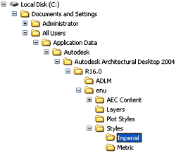 Both
the Imperial and Metric folders contain similar Styles
folders within which you will find three Spaces Style template drawing files.
On a Network based installation of ADT, these Space Styles should be on a captured drive (like "G:\offices standards") or similar location with a similar folder structure to that illustrated left (Content >> Imperial >> Styles >> Spaces - Commercial (Imperial).dwg, Spaces - Educational (Imperial).dwg, Spaces - Medical (Imperial).dwg and Spaces - Residential (Imperial).dwg or (Content >> Metric >> Styles >> Spaces - Commercial (Metric).dwg, Spaces - Educational (Metric).dwg Spaces - Medical (Metric).dwg and Spaces - Residential (Metric).dwg). In a very customized office scenario, these files may not even be present and others may have been designed for the Space styles your office prefers (in this case, see your CAD manager).
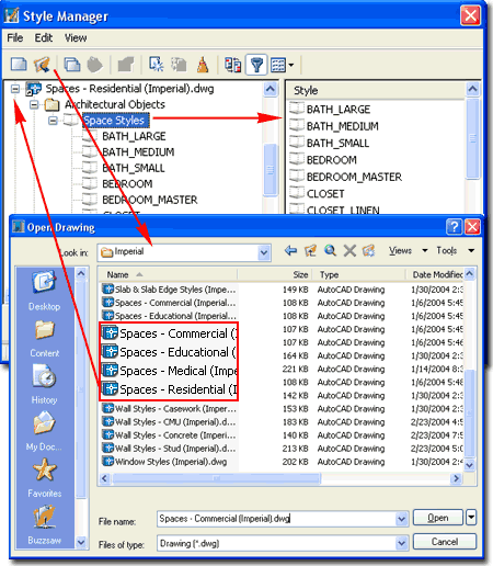
ADT comes with Commercial, Educational, Medical and Residential Space Style Files that each contain numerous pre-configured Space Styles. On the list below, right, you can see a few of the Space Styles that come with the "Spaces - Commercial (Imperial).dwg" file
| Links | Style Manager. - for more reading in the Development Guide |
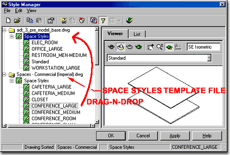
Once you have a Space Style template file Open in the Style Manage Window, simply select the Space Style(s) you want and drag-n-drop them on top of the current drawing file folder - as illustrated to the right.
In some cases, the list of Styles is so long that it takes too much time to scroll back up so you can use the left-click option and select Copy from the pop-up menu; then pick on the current drawing folder, pick in the right-hand pane, right-click on your mouse and use the Paste option. This technique is the same as that used in Microsoft's Explorer.
Those familiar with AutoCAD techniques, will also find that cut-n-paste works great for copying a Space Style from one drawing to another. Inserting a file, such as one of the Space Style template files also works to get every single Space Style in one quick action. If you want to use the insert trick, just hit the <Esc> key when prompted for an insertion point; i.e., you don't actually have to insert anything, just the action brings in all of the data.
| Menu | Concept>Spaces>Add Space... |
 |
|
| Keyboard | SpaceAdd |
Once you have Imported some Space Styles, you can Add any of these by selecting them from the Style drop-down list on the Add Space dialogue box (as illustrated to the right).
Style - a drop-down list offering access to any pre-defined Space Style loaded in your current drawing or the default "Standard". Space Styles are rule-based and using an inappropriate one can result in problems when you attempt to Modify them. When in doubt, select an oversized Space Style or use "Standard" and Modify later.
Floor Boundary - turn on or off the Floor component of a Space. Think of this as a Floor Slab.
Ceiling Boundary - turn on or off the Ceiling component of a Space. Think of this as the finished ceiling ( suspended or other ), but not as a Roof Slab.
Space Height - usually the height from finished floor to finished ceiling
Drag Point - a button that allows you to pick a different direction to orient your Space when you create it. Most, if not all, Spaces are automatically generated from left to right, relative to the cursor.
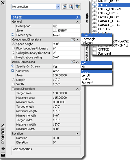
Specify on Screen - toggles the Area, Length and Width text boxes from locked to unlocked ( 2 at a time ) but you will be limited by some of the Space's Target parameters.
Area, Length and Width can be changed one at a time and are directly tied to the other two values. To acquire access to a locked value, lock any that is currently unlocked.
Space objects were the first solution for creating floor plates or slabs but also come with ceilings and database information that make them one of the most useful objects for managing construction estimates.
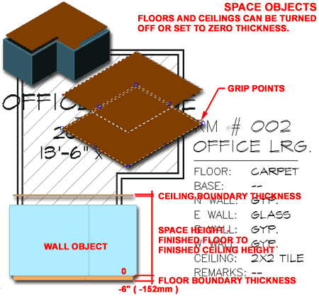
Illustrated to the right are some of the basic components of a Space object. Space objects have a Floor and Ceiling that you can turn on or off or even assign a zero value for thickness. The height between the Floor and Ceiling can also be controlled before or after creation by working with an individual Space object or by working with a Space object's Style.
When you create a Space object, either by Adding or by Converting, the Floor grows or extends from the ground plane down in the negative Z-axis direction making it ideally matched for use after Walls have already been added. Slabs, on the other hand, do not do this and must be moved down manually after creation.
In addition to their 3D geometric features, Space objects have been designed to work with several Annotation Tags and database Property Sets so you can easily attach such things as Room Numbers, Areas or Finish Lists. You can Export a huge amount of data into a common Microsoft Access MDB file format for use in other programs; even if you don't have Access.
| Menu | Concept>Spaces>Modify Space... |
 |
|
| Keyboard | SpaceModify |
The Modify Space tool opens a dialogue box almost identical to the Add Space dialogue box, so editing here is just like creating - see comments for Add Space, above.
![]() For more extensive editing options, use the Properties
button on the Modify Space dialogue box - see illustration, right. On the Space
Properties dialogue box, Dimensions offers the most extensive options for controlling a
Space but be aware that Space Styles constrain a Space's dimensions so that they remain
within pre-defined values for that particular type of Space. In other words, don't
expect to turn an Office into a Hotel Lobby; change the Style instead.
For more extensive editing options, use the Properties
button on the Modify Space dialogue box - see illustration, right. On the Space
Properties dialogue box, Dimensions offers the most extensive options for controlling a
Space but be aware that Space Styles constrain a Space's dimensions so that they remain
within pre-defined values for that particular type of Space. In other words, don't
expect to turn an Office into a Hotel Lobby; change the Style instead.
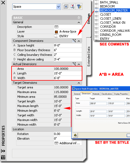
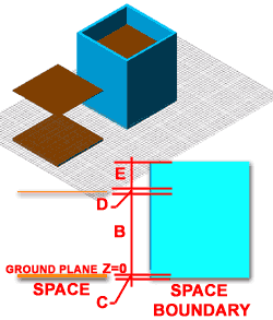 Space Styles don't store or determine Component Dimensions, so you set these
values here on the Dimensions tab.
B - Space Height - finished floor to finished ceiling height.
C - Floor Boundary Thickness - top of finished floor measured down in a negative z-axis direction to bottom of floor mass ( or slab ).
D - Ceiling Boundary Thickness - bottom of finished ceiling ( like a T-bar type ) to top of finished ceiling. If you want a Ceiling Mass instead of a T-bar type, simply set the Thickness accordingly. This is not to be confuses with a Roof though in quick study work it will look as a flat roof slab and there's no reason why you can't think of it that way until you get to more serious work. In many cases, I end up turning this component off and use Roof Slabs - especially if you want vaulted ceilings.
E - Height of Space Above Ceiling Boundary - this affects the way your Space works with a Boundary. When you convert a Space into a Space Boundary, the Boundary will rise above your D-Ceiling Boundary Thickness by the amount specified by E-Height of Space Above Ceiling Boundary. This provides room for a Roof or Roof Slab.
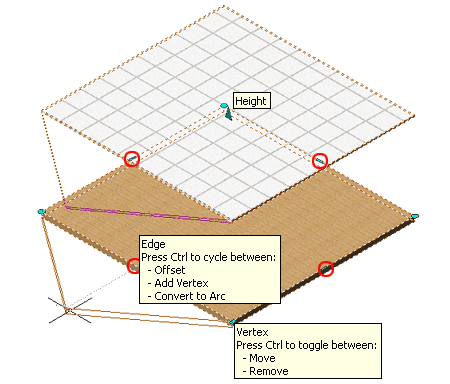
In the illustration to the right, I show the Grip points that you can use to Move, Copy, Rotate, Mirror and Stretch a Space object from but I also show what happens when you use Stretch to modify a Space object.
Unfortunately, the Constraints on a Space object don't work outside the dialogue boxes so when you Stretch a Space, you have no idea that you are actually exceeding the Space Style's constraints and this will only become apparent the next time you use the Modify Space dialogue box to make other changes. Illustrated to the right, I show the Warning dialogue that comes up after having Grip Stretched a Space object to a size way beyond what the Style allows.
I guess the moral of this tale is don't Stretch Spaces unless you are working with a Space Style that can range in size from a cubic unit to a million cubic units of space - doesn't really make sense, does it. Actually, working with more dynamic space Styles can really be beneficial in rapid design. You can experiment with the Standard Space Style and then, once you get spaces close to the sizes you want, you can switch them over to actual defined Space Styles.
| Menu | Concept>Spaces>Join Spaces |
 |
|
| Keyboard | SpaceJoin |
If you select any Space object and right click on your mouse to invoke the object pop-up menu, you should have the following options: Join, Swap, Divide, Edit Space Style..., Space Modify and Space Properties.
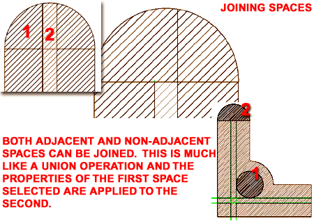
Join - will allow you to union two spaces; even distant ( non-adjacent ) spaces. The properties of the first Space selected will be applied to the second, when joining.
To break two non-adjacent Spaces apart that have been Joined, simply use the Divide Spaces tool and draw a division line between them; even though there are no objects there.
| Menu | Concept>Spaces>Divide Spaces |
 |
|
| Keyboard | SpaceDivide |
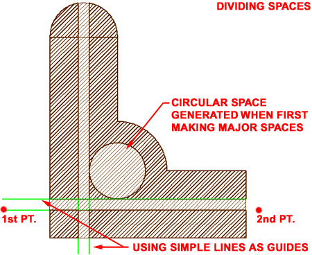
Divide - will allow you to split spaces into two parts based on two selected points (like drawing a line). This division is limited to a linear path and cannot be used to create curves or circular Space Divisions.
Select a Space object and then pick two points along the path where you want to create a division in the Space.
Illustrated to the right, is a single floor of a commercial office building where the primary egress corridors and a couple of offices have been created by using the Divide Spaces command. The circular Space near the center was created earlier by using the Generate Spaces tool instead of the Convert to Spaces ( which converts Polylines but doesn't allow for island selecting ).
Swap - will allow switching of spaces, but the spaces must be within a Boundary.
| Menu | Concept>Spaces>Interference Condition |
 |
|
| Keyboard | SpaceInterference |
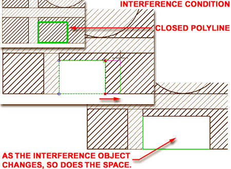
With the Space Interference Condition tool, you can introduce objects whose final dimensions are inconclusive at the time that you are designing. Using something like a Rectangle for a Mechanical Space will allow you to change this object easily without having to be concerned about Space Styles or other related design issues. The Space that is the recipient of this Interference will automatically adjust as will the resulting Area calculations for schedules and Space Tags ( you can actually see the Area on a Space Tag change in live mode as you adjust an Interference object.
Many different ADT objects can be used as interference objects, so you are not limited to Closed Polylines.
If an Interference object is Deleted, the Space restores to its original dimensions.
| Menu | Concept>Spaces>Convert to Spaces... |
 |
|
| Keyboard | SpaceConvert |
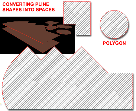
The Convert to Spaces tool only works on closed polylines, including rectangles and polygons so there isn't much to discuss on what to do with this tool. If you want a circular Space, as illustrated to the right, you can use a Polygon with many sides to approximate a circle.
Though you can convert just about any closed polygon into a Space object and Style, not all Styles match what you may have sketched out in Pline form so be aware that you may be assigning a particular Space Style to an Area that exceeds the Style's constraints. Doing this will eventually come back to haunt you, especially if you use the Modify Space dialogue box.
Basically you have two strategies to choose from when converting a Pline sketch of a building into Space: one strategy is to convert the whole shell into a Space and then begin to break it up, the other strategy is to draw all of the individual spaces in Pline form and then Convert them to specific Spaces.
If you are not interested in using Spaces for Space Planning but rather to create a Floor and Ceiling for an existing design, then you may want to want to create some more generic Space Styles that can accommodate a more diverse range of Areas. At times, I just use the "Standard" Space Style and worry about specifics later.
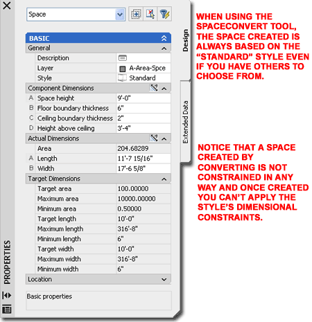
When you select a Polyline to Convert into a Space object, you will be prompted to "Erase layout geometry? [Yes/No] <N>:" and then you will see the Space Properties dialogue box illustrated to the right.
If you choose to Erase layout geometry, it simply means that the Polyline will be erased. In the case of using Slices, this is probably a good idea since the Slice can be used to generate a new Polyline at any time you want.
On the Space Properties dialogue box, you can choose any pre-defined Styles on the Style tab or use the Standard Style as a default choice. Though you can do some rather silly things here, like select an entire building perimeter and set it to a Closet Space Style, you probably want something as close as possible to the real definition of what you are converting to a Space. If you are converting a large area, as illustrated above, that will simply serve as the basis for further refinement I recommend using the Standard Space Style. If you choose one that is set to an Area much smaller than the resultant area of your Converted Polyline, you will encounter problems later when you attempt to Modify that Space object. Though these problems are not detrimental, they are really irritating.
On the Dimensions tab of the Space Properties dialogue box, also illustrated to the right, you can make on-the-spot dimensional changes. See Add Space dialogue box for more information on these value fields.
One of the more perplexing tasks in ADT is figuring out how to deal with Floors. If you tackle the development of your project from the Concept / Modeling path, moving from Masses to Slices to Spaces and Boundaries, there does not seem to be a problem with Floors but a lot of ADT users start from the Design tools where there is no command for Floors.
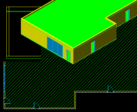
The way most people are solving the problem of creating floor plates or boundaries is to trace the perimeter of a building's Walls with the Pline command. Once you have a Pline perimeter, you can use the Convert to Spaces button to create a floor below (the default) or above your Walls. As discussed in the sections above, a Space will also provide you with a Ceiling.
Note: You can generate the perimeter Pline needed for the Convert to Spaces command by using the Slice Floor Plates command from the Concept pull-down menu. You can also save even more time by using the QuickSlice command from the Desktop pull-down menu to AEC Utilities... Since the QuickSlice command cuts in the Z-plane, you will need to flip the UCS icon up on the X-axis to make this routine work for slicing floor plates.
| Menu | Concept>Spaces>Generate Spaces... |
 |
|
| Keyboard | SpaceAutoGenerate |
| Links | Adding Room & Finish Tags - for manually adding Tags to Spaces after creation. |
The Generate Spaces tool is probably the best on in the whole set and yet it is placed so humbly in the middle that one could easily overlook it. It is based on a concept similar to that of BHatch and the Boundary command; by selecting objects that define your selection set, you then specify an internal point to get an internal perimeter object - in this case, a Space.
Selection Filter:
The Selection Filter is a drop-down list offering three option for selecting the
objects that define the perimeter that you want to capture as a Space object: Walls
only, Walls, lines, arcs, polylines, and circles or All
linework.
Walls only - filters out all objects
except Walls and Curtain Walls, though I have been able to select objects within Curtain
Walls ( which you need to do to get a proper read on Curtain Wall with nested entities).
Walls, lines, arcs, polylines, and circles - works like the Wall only
filter but includes the objects listed.
All linework - this finds just about everything and the problem with that
is that the resultant Spaces often don't make a lot of sense because you get Spaces out of
things like Mullions - use it as a last resort.
Style - this drop-down list is the same as that for Adding Spaces.
Modify Boundary Set - a button that allows you to reselect your objects completely or "Append to Current Selection Set" by any of the three Selection Filters. In other words, it basically takes you back to the first Selection Filter dialogue box.
Update Space - a button that allows you to select an existing Space object and have it automatically adjust to the new Selection Set derived by the whole process of Selecting Objects via the Selection Filter and picking an internal point.
Site - this is a text field where you can manually write information for each Space. By default you may see the two fields labeled as "Site" and "Site" but on the Tag Settings dialogue box, accessed through the Tag Settings... button, you can change these field names on the "Property 1:" and "Property 2:" drop-down lists - see image, right.
Site - see comments above.
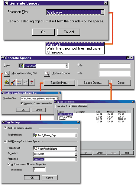
Tag Settings... - this button
brings you to the Tag Settings dialogue box where you can specify which tag you want to
have automatically Added to your Space objects as you create them. There are three
default Space Tags that you may want to use but first you will need to load them into your
current drawing. Documentation>>Schedule Tags>>Room and Finish
Tags... Drag-n-drop any or all of the three tags in from the DesignCenter.
You can also specify a Property Set to automatically add to each Space object as you
create them. This is the database information attached to your objects that you can
export or access via the object specific right-click pop-up menu - Edit Schedule
Data...
Space Query... - this button
brings you to the Space Information dialogue box, where ![]() you can can
identify Spaces and Areas and Export Space data to an Microsoft Access MDB file ( this can
be imported into Excel via Data>>Get External Data>>New Database Query...).
You can also acquire access to this dialogue box via the Space Inquiry button.
you can can
identify Spaces and Areas and Export Space data to an Microsoft Access MDB file ( this can
be imported into Excel via Data>>Get External Data>>New Database Query...).
You can also acquire access to this dialogue box via the Space Inquiry button.
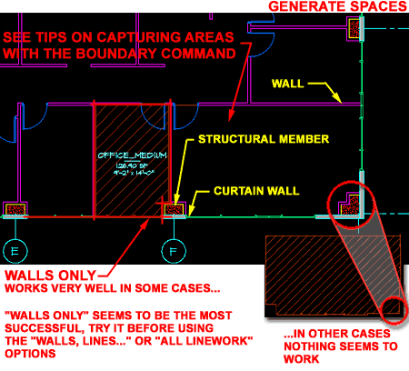
Illustrated to the right is an example of a fairly common commercial office space in a highrise or multi-floor building. If you are trying to capture areas of spaces surrounded by structure, try using the Walls only filter on the Generate Spaces first since it seems to be the most successful at reading enclosed areas when you are asked to "Select internal Point..."
Obviously if the space you are trying to capture isn't completely surrounded by Walls, the task becomes more difficult. Even when there is a "wall" structure around a space, such as that illustrated to the lower right ( with a Curtain Wall around the outside ), you may not be able to get the results that you seek with any of the three Selection Filter options (Walls only, Walls, lines, arcs, polylines, and circles or All linework). In cases like this, you can use other AutoCAD based tricks and combine them with ADT tools to make the process work faster. In the scenario illustrated to the right, I set the Display Configuration to Reflected, use the Boundary command to capture the inside space and Convert the resultant Pline into a Space.
Note1:
For BOMA standards on Area calculations, you will need
to adjust these Space objects to match centerlines of surrounding Walls ( where
appropriate ). I have not found a great solution for getting Space objects that
automatically go to centerlines of internal walls. You can try using the Sketch
Configuration Set but it will only work if your Walls were drawn with a Centerline
Justification. However, if you did draw your Walls that way, you can also
use the Boundary command to capture these spaces correctly.
Note2:
ADT 3.0 also shipped with Area tools which we will discuss in Part
20, but for labeling a Space, as illustrated, this seems to be the best way to
work.
| Menu | Concept>Spaces>Space Styles... |
 |
|
| Keyboard | SpaceStyle |
| Links | Loading Space Styles |
| Modify Spaces |
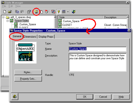
For Space objects, you can use the Style Manager to load, modify, delete and create new Space Styles.
Illustrated to the right, I show the process of creating a New Space Style that I have Named "Custom_Space". By double-clicking on this new style, you will invoke the Space Styles dialogue box - as illustrated.
The General tab provides access to the Name and Description fields for a Style; plus access to the attachment of Notes and Property Sets.
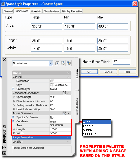
On the Dimensions tab of the Space Style Properties dialogue box, you define the ranges of your Space objects created with this Style. These are basically constraints that define the Optimum, Maximum and Minimum distances for the Length and Width of your Space(s). Based upon these ranges, you also need to take into account the resultant Areas which also have an Optimum, Maximum and Minimum range.
The Optimum or Target Area must equate to the formula Target Length x Target Width and the Minimum Area must equate to no less than the Min. Length x Min. Width. The Maximum Area cannot be less than either the Target Area or the Min. Area, but can be as large as you want it to be regardless of the Max. Length and Max. Width. In the illustration to the right, the Max. Area is set to 400 SF which prevents the the Max. Length x Max. Width from creating anything larger though they could conceivably create a 900 SF Area. Along the same line of thinking, if the Max. Area was set to 1000000 SF, you would not be able to reach this value because the Max. achievable Area is still held by the 900 SF set by the Max Length and Width.
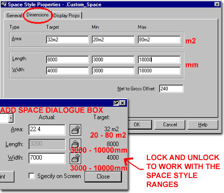
 The ranges that you set on the Dimensions tab of the Space Style
Properties dialogue box, have direct impact on how you can work with the Add Space
fields - see illustration to the right. Though one value always remains locked, you
can change any locked value by locking another. Setting one value, like Length and
locking it, allows you to work with the Width or the total Area against that Length value
( which is now locked ). When you go beyond the range of the Space Style, you will
get a warning dialogue box followed by automatic adjustments to your last input.
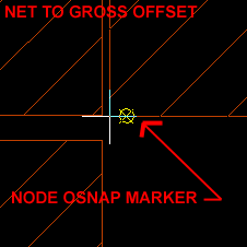
The Net to Gross Offset value field has significant return on investment if you know how to use it. This option is poorly illustrated but is simple to use if you know that you are supposed to use the NODE OSNAP when working with Space Styles that have a Net to Gross Offset value set. This value provides an automatic gap or distance between Spaces to accommodate such things as Walls. To take advantage of it, make sure to only work with your OSNAP set to NODE and it will all suddenly be so clear.
| Links | Drawing Setup Dialogue Boxes - for where to change the Metric units of measure to Meters, Millimeters, Square Meters, etc. |
See comments above.
| Links | Object Style Display Properties Overview |
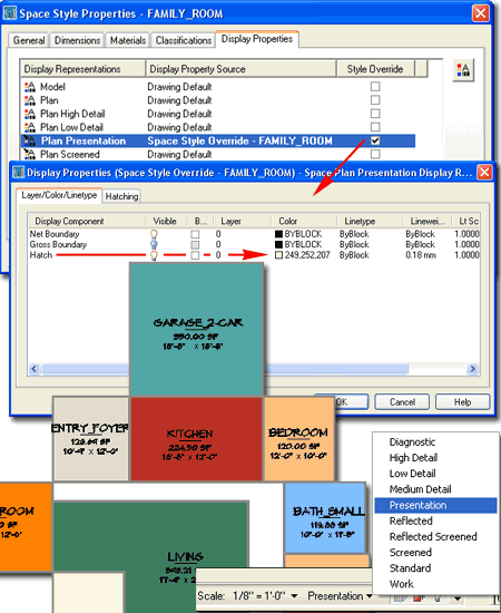
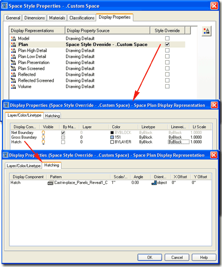
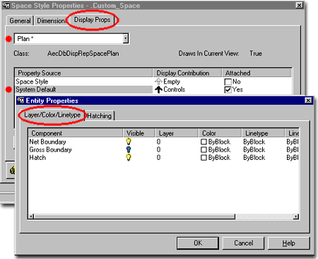
The Display Props tab of the Space Style Properties dialogue box provides access to some simple display options. Space objects do not have many components so there is a very limited, though useful, set of controls. You should find on the Layer/Color/Linetype tabs of most of the display representations, the option to turn on/off Hatch and Boundary - as illustrated below.
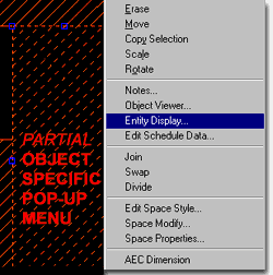 Illustrated to the left, is another way to access the Display Props
tab; select the specific object, right click
on your mouse to invoke the object-specific pop-up menu and select Entity
Display... See discussion directly below.
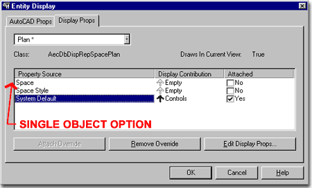
The Display Props discussed above right can also be accessed directly via the Object Specific pop-up menu, illustrated above left. Using this technique, offers a unique Property Source on the Display Props tab: one for the currently selected Object only. This is how you can quickly select one of several Spaces, for example, and change the type and/or color of the Hatching.
Look for this option/technique on all of ADT's Objects, even those that do not have Styles.
From the Display Props tab, in Plan view or other Representation Sets, you can use the Edit Display Props... button to access the component's Layer/ Color/ Linetype tab.
From this point, you can not only turn components on or off but change their layer, color and linetype. This is where, for example, you can create Spaces that have solid hatch patterns in unique colors.
Setting the Representation Set to Model, for example, and going to this Layer / Color / Linetype tab will allow you to change all of the Component colors so that they look more appropriate for 3D viewing and presentation. In cases where you plan to assign Rendering Material ByColor, this can also be of substantial advantage. For other unique options, take a look at the Component choices for the Section Representation.
| Menu | Concept>Spaces>Space Inquiry... |
 |
|
| Keyboard | SpaceQuery |
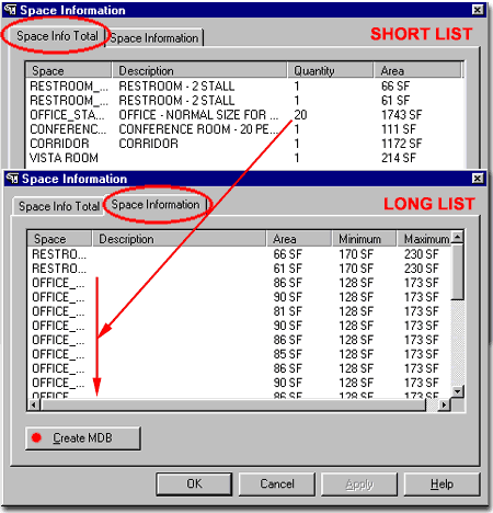
There are two aspects of the Space Information dialogue box that I find very useful. The first has to do with the fact that you not only get to see your Space Areas, but that you can find specific Spaces in your drawing by selecting them in the Space list. In other words, ADT will highlight the selected Space objects as you go down this list.
The other incredibly useful aspect of the Space Information dialogue box is the ability to generate a table with the Create MDB button.
| Menu | Concept> Space Boundaries >Convert to Boundaries... |
| Keyboard | SpaceBoundaryConvertSpace |
When you are ready to take Spaces to the next phase of development, you will need to use Space Boundaries. Space Boundaries, as a Solid Form Segment Type, can be converted directly to Walls.. This means that if you are ready to go from Spaces to Walls, you will need to use the Convert to Space Boundaries tool as part of the process.
On the other hand, if you simply want to work with your Spaces in a form that is a little more sophisticated, Space Boundaries offers a higher level of Space Management.
Read Architectural Desktop 3 Pre-design eGuide - Part 5 - Space Planning - Boundaries for more.

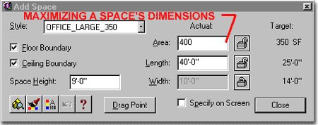
Just to further clarify the values that are being set in the dialogue box, above right, let's compare those numbers to what you can do with them in the Add Space dialogue box.
When you Add a Space it will default to the Target values but you can make changes to the Length and Width within the the range you defined for the Target Area. However, unless you unlock the Area text field and type in a new desired Area, you won't be able to work with the Max. extreme of your Space Style Dimension Properties. By changing the Area in the illustration to the right, I was able to set the Length to 40'-0" the extreme Max. I set for this Space Style. And, that forces the Width to go down to 10'-0".
There is plenty of information about Display Properties throughout
this e-book, but there are some interesting changes you can make to the Display Properties
of Space Styles that could really make presentations more vibrant.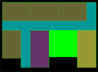
In the illustration to the right, I have set the Display Props View to Plan, Highlighted the Space Style in the Property Source list and Attached an Override that will allow me to work on the Layer/ Color/ Linetype and Hatching features uniquely for this particular Space Style. The reason I chose to use Attach Override for the Space Style, was to have the freedom to assign the Hatch pattern a unique Color; a color that will then only be shown when I use this particular Space Style. For Hatching, I show that by picking on the Pattern icon, a Hatch Pattern dialogue box pops up allowing me to use the Solid Fill pattern.
