PART 5
RENDERINGContents:
Render - Access ---- Render dialogue box ---- Rendering Types and Rendering Options ---- Rendering Destination ---- Rendering Preferences & Statistics ---- Customizing and Tricks
| Architectural
Desktop 3 - Presentation Guide PART 5 RENDERINGContents: Render - Access ---- Render dialogue box ---- Rendering Types and Rendering Options ---- Rendering Destination ---- Rendering Preferences & Statistics ---- Customizing and Tricks |
| 1Render - Access | .1-5 RENDERING | ||||||||||||||||||
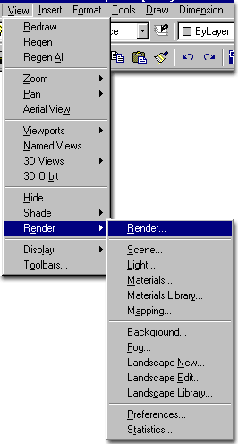
How do I get this toolbar? You can also acquire access to this command from the View pull-down menu. From the View pull-down menu, pick Render > and cascade to the Render... option. |
 |
||||||||||||||||||
| Render pull-down menu Illustrated to the right, I show the Render pull-down menu which consists of all the same tools as those found on the Render toolbar. I have always been a fan of this toolbar because I really like the button icons, don't you? Though Render... is the top option over on the Render > cascading menu, it is unlikely that it will be the first thing you will do when getting ready to create a rendering. This is because renderings don't look very good without the other options such as Light, Materials and Backgrounds. Light, for example, should be your first concern because as in the "real" world it is required to see the environment. A simple trick I often use when in a hurry, is to simply drop in a single source of Light that I like to call the "Sun" ( Distant Light ). Even in an interior shot, you can use a single source of light to quickly create shadows and contrast. It would thus seem logical that I present and discuss Light first in this Guide but since you are not forced to use any of these other tools to create renderings, we might as well look at the Render dialogue box first and then discuss what these other tools can do to improve your renderings. This means that you may want to read up on Light, Materials, Material Mapping, Backgrounds and Landscape objects before attempting to understand everything about the rendering dialogue box. If this is your first time through this subject and this material, I recommend that you run through the information below lightly and then move on to Light, for example, and then return to this material. In other words, I see Part 5 - Rendering as a place you may return to again and again as you learn more about the other options and how they play a role in generating renderings. |
 |
||||||||||||||||||
| 2Render dialogue box | 2-5 RENDERING | ||||||||||||||||||
Render dialogue box options broken down
The Render dialogue box, illustrated to the right, is the primary tool for generating rendered images in or out of AutoCAD and Architectural Desktop. Though there are numerous other settings and tasks that need to be completed for great renderings, none of that work will mean anything if the Rendering dialogue settings are not set correctly. Rendering Type Scene to Render Rendering Procedure Crop Window - this checkbox will allow you to specify the area of your screen to Render. The request to Specify Crop Window will occur after you pick the Render button. This is another great option to save time and can be used to test a small area to see if lighting, materials and shadows are coming out okay. Skip Render Dialog - this option will turn off the Render dialogue box the next time you execute the Render command. If you accidentally set this option, you can restore the normal unchecked mode by using the Rendering Preferences button. Light Icon Scale - use this number field to control the size of Light Blocks in your drawing. For architectural buildings, you will probably want an icon size of 10 (imperial or 1000 metric) or greater. Once you have completed your next rendering, you will see the new Light Icon size. You can also use the Rendering Preferences dialogue box to change Light Icon sizes without having to run a Rendering.
|
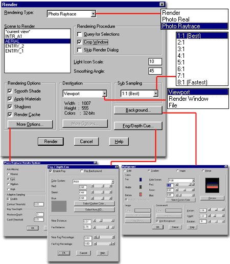
Rendering Options Apply Materials - check to render with Attached Materials. See comments below. Shadows - check to have Shadows generated. See comments below. Render Cache - check to have rendering done to hard-drive for quicker recall on next render. Destination Viewport - will produce the rendering in any currently active Layout Viewport or Model Space. This is probably the best option when developing a rendering, but obviously not a good option when you want to save it or print it. You actually cannot print a Viewport Rendering directly from AutoCAD or Architectural Desktop but you can Save it and then Print it - use SaveImg command or Print+Scrn keys on keyboard. Render Window - will produce the rendering in a separate Window where you can store several images, save them and print them. File - will produce the rendering in a raster file format such as .tif, .jpg, .bmp and .gif. When you select this option, the More options... button will become active and you can use it to specify the type of raster file format, the size and the quality. Sub Sampling - use this drop-down list to speed up rendering time but at a cost that is difficult to argue for. Changing the ratios is similar to reducing the pixels on your screen. The greater the ratio the lower the number of pixels Background... - use this button to access the Background dialogue box. Fog/Depth Cue... - use this button to access the Fog/Depth Cue dialogue box. |
||||||||||||||||||
| 3Rendering Types & Rendering Options | 3-5 RENDERING | ||||||||||||||||||
Rendering
Type
Render - this type of Rendering does not calculate Shadows nor anything other than the Color Attributes of Materials. Reflections, Transparency and other advanced Attribute options are not rendered. This is a good option for producing quick Renderings that appear similar to the various Shademode options that you have while working on your screen. See also the four options available on the Render Options dialogue box accessed through the More Options... button. Photo Real - is a step up from the Render type quality and offers the option to have Shadows as part of the output. For the most part, it produces a fairly decent output but has very poor results on Reflections and Refractions. Shadow calculations can also be less crisp and I have found that this type can often take longer than the Photo Raytrace type so I tend to only use Render and Photo Raytrace. See also the numerous options available on the Photo Real Render Options dialogue box accessed through the More Options... button. Photo Raytrace - offers the highest quality output with the most amount of options but will also draw the most from your system and take the longest amount of time to produce results. Raytraced Shadows, Reflection and Refractions are what make this type superior to Photo Real. See also the four options available on the Photo Raytrace Render Options dialogue box accessed through the More Options... button. Rendering Options |
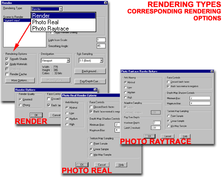
Apply Materials - check this box to have Materials rendered asAttached and Mapped to your objects. If this option is not available, use the Render Type drop-down list to choose Photo Real or Photo Raytrace. In order to show Materials, Materials have to be Attached with the Materials dialogue box. Shadows - check this box to have shadows cast from lights in the drawing. If this option is not available, use the Render Type drop-down list to choose Photo Real or Photo Raytrace. In order to show Shadows, Lights have to be assigned to the current drawing with the Lights dialogue box. Lights have their own Shadow on/off settings as well and you may have to check each Light to see if its ability to cast Shadows is on. Render Cache - check this option if you plan to re-render the same scene more than once. By Rendering onto a portion of your hard-drive, the Renderer can quickly recall calculations from the previous Rendering to save you time. More Options... - use this button to access more setting for each of the three Rendering Types. See comments below for each of the three Options. |
||||||||||||||||||
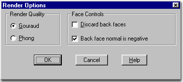
| "Render" Options dialogue box Illustrated to the right is the Render Options dialogue box acquired from the More Options... button on the Render dialogue box for the Render Type "Render". Gouraud - this option is the default option for rendering since it produces faster results but at a lower quality. Phong - this option produces a higher quality rendering than the Gouraud option and you should notice better looking highlights on curved edges but at a cost of more rendering time. Face Controls Back face normal is negative - checking this option keeps the normals of faces as determined in AutoCAD by default. This is where faces drawn in a counter-clock wise fashion have positive normals ( Z-axis ) pointing outward. Unchecking this option reverses the normals and thus has a dramatic impact on how the Discard back faces option affects your Rendering;e.g., if you uncheck this option and check Discard back faces, all of the front faces of your objects will be removed resulting in a Rendering full of hollow objects where you can see the back faces only. |
|
||||||||||||||||||
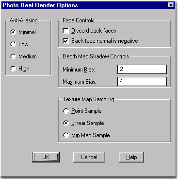
| "Photo Real" Render Options dialogue box Illustrated to the right is the Render Options dialogue box acquired from the More Options... button on the Render dialogue box for the Render Type "Render". Anti-Aliasing - a process in which efforts
are made to reduce the jagged effect caused by pixels ( particularly across diagonal paths
). Higher resolutions ( more pixels ) usually require less
anti-aliasing. The cost of anti-aliasing is Rendering time and thicker
lines. The amount of anti-aliasing desired for a screen Rendering may be
greater than that needed for the final output ( web, paper, slide, etc. ). Face Controls - See "Render" Options dialogue box Depth Map Shadow Controls - Affects Shadow
Maps only; a setting determined by what you set on the Light dialogue box for each Light. Maximum Bias - this setting affects the far distance between a shadow and the object casting this shadow. The lower this value is set the greater the spread of the shadow; which includes back shadowing on the light side. |
 |
||||||||||||||||||
| "Photo
Raytrace" Render Options dialogue box Illustrated to the right is the Render Options dialogue box acquired from the More Options... button on the Render dialogue box for the Render Type "Render". Anti-Aliasing - see "Photo Real" Render Options dialogue box Adaptive Sampling - a separate control option to assist in reducing Rendering time for anti-aliasing. Enable - on/off. Contrast Threshold - the range for this value field is between 0.00 and 1.00. Use this range to help the Renderer determine when to re-sample and when to leave the pixel information without re-sampling. The numbers signify a threshold of variation between pixel shades so you might say that if the value is set to .50, the Renderer will ignore the shades if they are less than 50% different ( this may not be the exact method but serves as an analogy ). Ray Tree Depth - affects Photo Raytrace
Rendering Type only. Cutoff Threshold - this value field with a range between 0 and 1.0 can be used to control the point at which the Maximum Depth discontinues the calculation process. This means that if you set the value to 0.5, the Rendering process will cut off when the next pixel does not receive more than 50% of the information required to generate the image. Face Controls - See "Render" Options dialogue box Depth Map Shadow Controls - See "Photo Real" Render Options dialogue box |
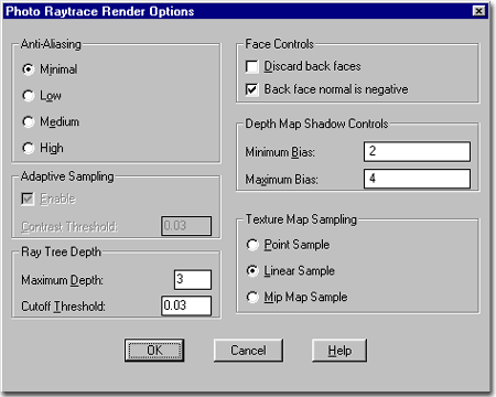
Texture Map Sampling - use
this when bitmap images appear jagged or rough on Attached objects in a Rendering.
Usually the problem is greatest when using poor bitmaps with low pixel counts or when
stretching a bitmap out over a large surface disclosing the individual pixels. These
sampling techniques help to gauge the best color for a pixel in a sample group and can
thus help to smooth out an image. Linear Sample - this setting uses the closest four pixels within a sample to produce the color of a pixel. Mip Map Sample - this setting uses a pyramidal method to evaluate pixels within a sample to produce the color of a pixel. Its results are so close to the Linear Sample option that I did not attempt to illustrate this method. |
||||||||||||||||||
| 4Rendering Destination | 4-5 RENDERING | ||||||||||||||||||
Render
to Viewport
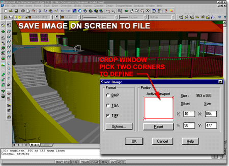
AutoCAD and Architectural Desktop use the Viewport Destination as the default place to produce Rendered images in new drawing files. Since the term Viewport is used to describe a number of working environments, you can actually Render in any of them; this list then includes, the whole working screen Viewport, any or all Tiled Viewports and any or all Layout Viewports ( also known as Mviews ). The most frustrating thing you will probably face with Rendering in Viewports is that you cannot use the Print or Plot command to output what you see on your screen. You can have a great Layout setup with perspectives, plans and one or more Renderings and yet you cannot print the layout with those Rendered images unless they have been saved separately and then brought back in with ImageRef or equivalent technique. There are only two methods, that I am aware of, that you can use to at least Save a Viewport Rendering for future printing and they are: the SaveImg command and the Prnt+Scrn keyboard strokes. |
 |
||||||||||||||||||
Render
to File
The File Output Configuration dialogue box, illustrated to the right, is accessed through the More Options... button on the Destination portion of the Rendering dialogue box. The Destination Type must be set to File for the More Options... button to be active. When you are ready to produce the final Renderings for you project(s), the best way to produce high quality Renderings is through the File Method. To the right I show just a few of the options that are available for output files. Though the world of Raster Images and file types is far more complex than what most CAD users deal with, the concept is quite simple: you want the largest, cleanest and sharpest image with the most amount of colors that can be Rendered as fast as possible. Anything after the process of creating a good output can be adjusted with Photoshop or an equivalent raster image editor. File Type Image Resolution drop-down list - this list offers sizes ranging from 320x200, predefined, all of the way up to 4096x4096, User Defined. These ratios are based upon monitors and pixel sizes but you can use the User Defined option to create your own ratio. X, Y and Aspect Ratio - these options are available only when User Defined is set on the Image Resolution drop-down list. X, represents the number of pixels you want along the horizontal direction of the image and Y, represents the vertical number of pixels. The Aspect Ratio of the pixels defines the proportion of each pixel. In Television, for example, the ratio is something like 2 or 3 to 1. The more equal the ration the cleaner the image. By creating your own X and Y size, you can emulate output that looks more like Wide Screen imaging.
|
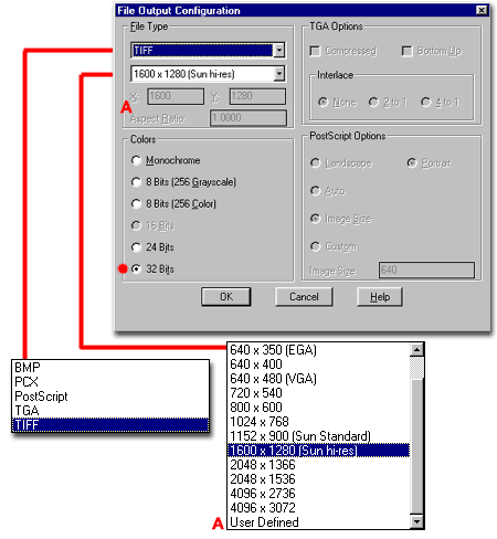
TGA Options - Bottom Up - this option controls how the file is read; from the bottom instead of from the top. This would only be noticeable on massive files or overloaded machines where you have to wait for the file to load. Interlace - this option controls how a file is read on
screen. I use Interlacing extensively in these guides to make the images appear
faster but then they have to scan a couple of times to become clear. For
TGA files, you may need this on huge files so you can see the image in scans of clarity. 2-1 - two scans before fully loaded 4-1 - four scans before fully loaded. Postscript Options Auto - this option calculates the image size base upon some ratio that I was unable to confirm at the time of this writing. It tends to produce small sizes. Image Size - this option produces a size based upon that specified under the File Type drop-down list. Custom - this option
activates the Image Size value field where you can specify a unique output size for the
width of the Rendering. |
||||||||||||||||||
Render
to Window
The Render Window, illustrated to the right, provides an intermediary solution between Viewport ( your screen ) and File ( not seen ) for outputting Rendered images. With this Destination option, the Rendering is placed in the Render Window outside of the AutoCAD's and Architectural Desktop's Window so you can view the Rendering, Print it, Save it and even compare several versions.
From the File pull-down menu on the Render Window, use the Options... menu item to access the Windows Render Options dialogue box, illustrated to the right. On the Windows Render Options dialogue box, set a Bitmap size according to your needs ( User Max. = 4096 for both Horizontal and Vertical ). You should also set the Color Depth to 24-Bit no matter what since 8-Bit is so poor that it's horrible to look at. Use the Fit in Window checkbox for autosizing so you can see the full image even when Rendered to a pixel size greater than your screen resolution. Fit in Window does not affect the quality of the Rendering. Open... - use this option if you want to look at .bmp images only. It cannot open other formats so that makes this feature a little limited. Save... - use this option to save any Renderings that you currently have in the Render Window. The bitmap image format that you can save to is limited to .bmp which is one of the worst options, unfortunately, and thus limits the value of the Render Window substantially. See Part 13 - Graphic Content - Raster File Formats for information about .bmps |
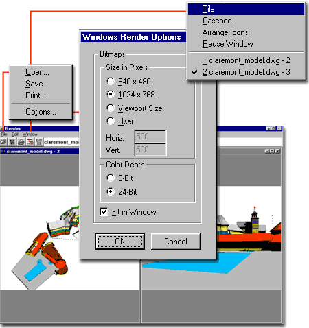 Print... - use this option to print any of the Rendered images in the Render Window directly to your printer or plotter ( whichever is set as the default system printer ). The Print dialogue box offers a unique opportunity to resize, distort, position and spread an image across several pages before printing. Unfortunately it does not provide the option for printing all of the images in the Render Window simultaneously on one sheet which would be a nice addition; especially for running proofs. Edit pull-down menu - this menu only offers the Copy command and that is really the Copy to Clipboard command which allows you to Paste the Copied Image into another program like Word. Window pull-down menu - among the typical Microsoft options on this pull-down menu, you will find one that is unique: Reuse Window. Use this option if you do not want all of your sample Renderings pilling up in the Render Window and using up precious memory on your system. |
||||||||||||||||||
| 5Rendering Preferences & Statistics | 5-5 RENDERING | ||||||||||||||||||
Rendering Preferences dialogue box
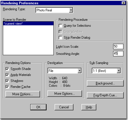
The Rendering Preferences dialogue box, illustrated to the right, can be used to set all of the default settings you want when Rendering. By using the Skip Render Dialog option, you can even deactivate the Render dialogue box so that when you execute the Render command, rendering begins immediately. Though I do not like to work without the Render Dialogue box, I do use the Render Preferences dialogue box to change the Light Icon Scale. One of the other reasons for this option is to allow for scripts that render a series of scenes while you sleep at home. See Render dialogue box for explanations of all the options available on the Rendering Preferences dialogue box. |
 |
||||||||||||||||||
Rendering Statistics dialogue box
The Statistics dialogue box, illustrated to the right, offers a way to read a report on the Rendering dialogue box settings, Rendering time and a host of other interesting facts about your Model. The more Faces and Triangles, the bigger the file and the longer the Rendering time. In professional Rendering situations, using high-end programs, they refer to these as polygon counts and for work such as game design, keeping a low polygon count is very important for speed of play. Save Statistics to File - use this checkbox and adjacent text field to specify a Name for the current Statistics file. When you type in a Name, make sure to include a three letter extension. I have used both .txt and .doc and they both work fine. Find File... - use this button to specify a location for your Statistics file. |
|
||||||||||||||||||
| 6Customizing and Tricks | 6-5 RENDERING | ||||||||||||||||||
© Copyright 2002 ARCHIdigm. All rights reserved.
spell checked on Jan. 24, 2002 (gr)