PART X
APPENDIXContents:
Creating a Rendering Studio Template File ---- Unloading the Render Application ---- Options Configuration ---- Adding a Raster Plotter ---- Downloads ---- Links to other Sources
| Architectural
Desktop 3 - Presentation Guide PART X APPENDIXContents: Creating a Rendering Studio Template File ---- Unloading the Render Application ---- Options Configuration ---- Adding a Raster Plotter ---- Downloads ---- Links to other Sources |
| 1Creating a Rendering Template File | 1-X APPENDIX | |||||||||||||||||||||||||||||||||||||||
| Templates for Rendering As Architectural Desktop has evolved so has the validity of using Template
files. A good template file can shave an hour or more of labor off the
starting process of any drawing file so its accumulative return on investment goes beyond
simple arithmetic. For Rendering work you can also create Template
files that are all set to produce near instantaneous results. In the case of Lights,
for example, you can have a Sun ready to go and once created, changing it
is quite simple. In the case of Materials, for example, You can also create different Rendering Template
Files for different types of presentation work. One file might be used for simple
color renderings and another for high quality interior shots with lots of materials,
lights and props. |
 |
|||||||||||||||||||||||||||||||||||||||
| Rendering Template File -
Materials and Blocks The Rendering Template File can be loaded up with every default
Material you can think of using. With the AutoCAD Color Index ( ACI
) system you can assign up to 255 In addition to loading the Rendering Template File with Materials, you may want to load it with standard 3D objects ( or props as I like to call them ) for access through the DesignCenter - see illustration to the left. Blocks can carry Material Attachments as long as those Materials exist in the current drawing and library. Lights can be reside inside Blocks but must be Exploded after Insertion.
|
 |
|||||||||||||||||||||||||||||||||||||||
| Rendering Template File - Advanced For more advanced users, you may want to use some of the following tricks in your Rendering Template File: Create standard Light Types and make Blocks of them for quick and easy insertion. They must be Exploded upon Insertion to show up in the Lights dialogue box. Create various Landscape Objects with appropriate settings and sizes and make Blocks of them for quick and easy insertion. You can even make Blocks of clusters of various different combinations of Landscape Objects. Create dummy Xref files with Standard default Names so you can Attach Materials to Xref Layer Names that can be swapped for other Xref files without losing the Material Attachments - See below for more information. Illustrated to the right I show a trick you may want to use to keep track of light settings by using a graphical aid. In Autodesk Viz, for example, you can see the Light Cones in Wireframe to get a sense of how the light is set relative to objects. In AutoCAD and Architectural Desktop you can draw circles on the Defpoints Layer and Color code them to indicate Hotspot and Falloff settings. Unfortunately, Lights will not work inside of Blocks but you can Explode these Blocks upon Insertion and then use the Group command to keep them all together again. |
 |
|||||||||||||||||||||||||||||||||||||||
Rendering Template File - Automatic
Material Attachments with Xrefs
Another trick for more advanced users is to create a dummy set of plans for the standard set you use on projects; e.g., Site, Foundation, 1st Floor Plan, 2nd Floor and Roof. Xref these dummy models into the Rendering Template File and Rename the Xref's according to their function; i.e., Site, Flr_1, Flr_2, Roof, etc. Use the Materials dialogue box and Attach default Materials to the Xref'd Layers for all objects that you do not wish to use Color Attachments for. Now this Rendering Template file will be ready for any Xref'd files because you can simply use the Browse button on the Xref Manager dialogue box to find any new Xref file you want. By using the Save Path, you not only assure that the new model file will remain in the current Rendering Template File but that all of the Attached Materials have been transferred to the new Model file. Material Attachments follow the a hierarchy of *Global*, By Layer, By Color and finally by Attach. The direct Attach method overrides all other methods and is thus at the top of the hierarchy. |
 |
|||||||||||||||||||||||||||||||||||||||
| Rendering Template File - Saving You can Save your Rendering Template File(s) as an AutoCAD or Architectural Desktop template file ( Save As... (.dwt) ) to prevent accidental corruption. The template files typically reside in the Template folder under AutoCAD or Architectural Desktop in the Program Files folder on your computer. To edit or modify a template file, you can simply Open it in AutoCAD or Architectural Desktop by setting the Files of Type to ".dwt" on the Open dialogue box. In reality, the only difference between a template file and a drawing file is the last letter of the extension; i.e., Rename a .dwg to .dwt and you have a template file. |
||||||||||||||||||||||||||||||||||||||||
| 2Unloading the Render Application | 2-X APPENDIX | |||||||||||||||||||||||||||||||||||||||
Load/Unload Applications dialogue box
To unload the ACRENDER.ARX application and the Render Window, use the "APPLOAD" typed command to access the Load/ Unload Applications dialogue box illustrated to the right. On the Load/ Unload Applications dialogue box use the Loaded Applications tab to search for a file named "ACRENDER.ARX", highlight this file and use the Unload button to unload it. |
 |
|||||||||||||||||||||||||||||||||||||||
| 3Options Configuration | 3-X APPENDIX | |||||||||||||||||||||||||||||||||||||||
Options
- Files tab
On the Files tab of the Options dialogue box, illustrated to the right, you should find a folder called "Texture Maps Search Path" at the very bottom of the list of Search Paths. In order for AutoCAD and Architectural Desktop to function properly with respect to the Materials Library and the Bitmaps contained within it, the path must be set to find those bitmaps. Illustrated to the right, I show the default bitmap ( textures ) path for Architectural Desktop 3.3 but it should be very similar with other flavors and versions of AutoCAD and Architectural Desktop ( in fact, it hasn't changed in several years ). On a network or custom installation of either of these programs, the Texture Maps Search Path may be quite different and that is perfectly okay as long as the path is valid and there are bitmaps in it<hah>. I do find that pulling images through a network server does prove to slow the Rendering process down a little as does the process of loading the Materials Library dialogue box ( particularly on an active network with a large library ). It should also be noted that custom Materials and Material Libraries can be created that have full path statements to bitmaps and thus do not need this Search Path statement to function properly. The only problem with using a multitude of independent search paths is that they become "hard coded" with the Materials and thus if the paths should change, the materials act like Xref's that can't be loaded. A better solution is to simply Add... more Texture Search Paths. |
 |
|||||||||||||||||||||||||||||||||||||||
| Options
- Display tab On the Display tab of the Options dialogue box, illustrated to the right, there are several Display related options and settings that you can use to improve the performance or appearance of your 3D Modeling and Rendering work. Unfortunately, the performance aspect is usually inversely proportional to the appearance aspect so that a great looking Shaded Sphere, for example, also takes longer to turn while in 3D Orbit. The default settings, in my opinion, are unacceptable though so you should make some minor adjustments as outlined below. Display Resolution - See also Dynamic Tessellation setting. Segments in a polyline curve - ( SPLINESEGS ) - this variable affects Polylines only. It is best observed when using Pedit on Plines and using the Spline option to curve a jagged set of Plines. The range of values can be between -32767 and 32767.
Contour lines per surface - ( ISOLINES ) - this variable affects Solid objects only. The number of isolines helps in visualizing curvature in Wireframe Mode but does not apply to Rendering ( despite what the on-line help suggests ). Display Performance Highlight raster image frame only - ( IMAGEHLT ) - this variable is an interesting option that allows you to see the whole raster image area with a cross hatch pattern instead of just the frame. Make sure HIGHLIGHT is set on ( 1 ) for this to work. The problem with this option is that it makes it impossible to relate content on the image with any content on the screen so this is not an option I find particularly useful. True color raster images and rendering - ( VIEWRES ) - this variable is very important when Rendering images directly on the screen. True Color is 32bit and as long as your system is configured to display such a high level of color, you can see it on your screen and better judge the quality before committing to a super high quality File output. This variable affects Referenced Images as well and does degrade system performance. Apply solid fill - ( FILLMODE ) - this variable controls solid fills of Polylines with Width, Trace lines, objects created with the Solid command , old .shx Fonts that have fills and all Hatch patterns. When turned off, no fills or hatch patterns will show. This variable does not affect Rendering but does affect general display performance and is particularly useful on drawings with an enormous amount of hatch patterns. |
 Show text boundary frame only - ( QTEXTMODE ) - this variable turns all text objects into rectangular outlines. It does improve general performance a lot, but the rectangles do not represent the true outline of the text and can thus be a bit misleading about the position, height and width of text.
Other Display Variables that are not
listed here: AecFacetDev - ( FACETDEV ) - this variable is for Architectural Desktop objects only and has a huge impact on the appearance of curved AEC objects, from curved Curtain Walls to curved Roof fascias. The value is for the length of a chord along any curve so the shorter the distance ( smaller number ), the smoother the curve. The range is between zero and infinity and the default value is 0.5. You may find that you will need to use a value of 2 - 0.1 depending on what and how close you are Rendering. In some cases when converting AEC objects from Polylines, you may need to set this variable prior to the conversion; this is particulary true with Roof Slabs. Surftab1 - this is not a Display control but a tabulation setting for the creation of Surface objects in AutoCAD and Architectural Desktop. I have added them to this list for reference purposes in case you are also using Surfaces. The problem with these tabulation settings is that they cannot be set after the creation of a Surface but must be set prior to creating it. Surftab2 - see comments on Surftab1. This tabulation setting works for Surface objects that take two directions for tesselation; surfaces like EdgeSurf. |
|||||||||||||||||||||||||||||||||||||||
| Options
- System tab On the System tab of the Options dialogue box, illustrated to the right, you can use the Current 3D Graphics Display drop-down list to select other drivers or use the Properties... button to add one or make changes to the current driver configuration. The options you have depend greatly upon the configuration of the computer system you have and the type of video card that is installed. Though Autodesk claims that the AutoCAD kernal supports multi-threaded applications, the evidence as to the benefits appears negligible. I think it safe to say that the return on investment for multiple processors is far greater with products like 3D Studio Max and the new Autodesk Viz than with AutoCAD and its Flavors. Rendering in AutoCAD and Architectural Desktop is slow and will remain slow until a new Rendering engine is added. I have found that it is actually faster to run Architectural Desktop side-by-side with Viz. The Properties... button does provide access to some really cool options however so you should definitely take advantage of what there is to offer - see comments below. |
 |
|||||||||||||||||||||||||||||||||||||||
Options
- System tab - 3D Graphics System Configuration
The 3D Graphics System Configuration dialogue box, illustrated to the right is accessed through the Properties... button on the System tab of the Options dialogue box ( discussed above ). On this dialogue box you can make some significant performance changes to the display of your 3D Modeling work; including activating Lights and Materials in Shaded Modes. Adaptive degradation - check this box to allow for degradation options. Maintain speed in FPS ( Frames per Second ) - this value sets the point at which degradation will occur. If, for example, a model has all render options on and is being rotated in the 3D Orbit tool but cannot maintain a speed of 5 frames per second while displaying full render options ( textures, etc., ), the jump will be made to Flat shaded or any other option set. Note about degradation: this is a really useful option if you are pushing your system to its limits. If you like working with Render options on and find that the model hick-ups a lot and moves too slow when you are changing display angles, views and so forth, use the degradation options. Start with Flat shaded before using Wireframe. For most of my work I usually use the Wireframe option as illustrated to the right. If degradation kicks in too early, set the Frame per second value higher. Dynamic Tessellation - use these options to control smoothness of 2D and
3D objects viewed in the various Shademodes . Though it may be difficult to detect
much difference Surface tessellation - the higher the setting ( right ) the smoother the surfaces and the more draw upon your system's display resources. Setting this option low is less likely to be noticeable than setting the Curve tessellation value low because surfaces tend to be flat anyway. Curve tessellation - see comments for surface tessellation. Setting this option low is likely to be very noticeable - see illustration left. Number of tessellations to cache - a range field that can be set between 1and 10. Though this sounds like a control for number of lines or triangles, it is really more about the cache setting and typically becomes observable with multiple shaded viewports. Use a higher cache value for more viewports. Note about Dynamic tessellation: though I have no statistical evidence and every machine varies, I tend to find that dynamic tessellation with mid-high settings runs very well and perhaps better than static. Though this defies logic, I suspect that the caching has something to do with a perceived performance improvement. Run your own tests and see how your system behaves. These settings do no not affect Rendering. Render Options Enable materials - checking
this option allows Material Colors to show on surfaces in the various Shademodes and
enables further options for Materials. |
Transparency Geometry Discard back faces - checking this box will improve display performance by not calculating for hidden geometry behind visible geometry. Having this option on is best and usually is not a problem in Shaded views. This term and concept is also part of Rendering where it has to do with face normals and what is perceived as back and front - see Discard Back Faces as a Rendering option. Acceleration - this option is only of value to those who have advanced graphics
cards specifically designed to provide display benefits for CAD software. Hardware - use this checkbox to deactivate the default software driver and to select a new hardware driver. Driver - use the Browse... button to select the supplied "wopengl7.hdi" driver from Autodesk or one by the manufacturer of your 3D Graphics Card. Use geometry acceleration ( single precision ) - this option only works if your graphics card supports this option. Enable anti-alias lines - this option creates smoother geometry but adds more demand on the hardware. Note about Acceleration: choosing a hardware acceleration driver can be a very tricky business if you don't know what you are doing. Chances are that you will actually experience a performance degradation. When and if you experiment, make sure to test without the "Use geometry acceleration" and "Enable anti-alias lines" options to confirm any performance enhancement. Also, make sure to read up on your Graphics Card and read the documentation on this subject in your AutoCAD or Architectural Desktop manual. |
|||||||||||||||||||||||||||||||||||||||
| 4Adding a Raster Plotter | 4-X APPENDIX | |||||||||||||||||||||||||||||||||||||||
Plotter Manager - Add Plotter Wizard
When you are in need of better ways to get Raster Images out of AutoCAD and Architectural Desktop, you can use a Raster Plotter but you will have to Add one first. Using the Add A Plotter Wizard icon in the Plotters Window, you can use the My Computer radio button on the Add Plotter - Begin dialogue box as illustrated to the right. This will provide you with access to the raster plotter drives that come with the program.
|
 |
|||||||||||||||||||||||||||||||||||||||
| Selecting and Using a Raster Plotter After setting the My Computer radio button on the Add Plotter - Begin dialogue box, use the Next > button to access the Add Plotter - Plotter Model dialogue box, illustrated to the right. On this dialogue box you can choose from among several plotter models but for Raster output, you will probably want to use either the Adobe option or the Raster File Formats option on the Manufacturers scrolling list. For Raster File Formats, you will find a fairly long list of great formats such as .jpg, .png, .tif and .tga. For the Adobe Manufacturer, you can choose .eps ( level 1 or 2 ). This is a favorite among AutoCAD users who work with Illustrator to punch up regular vector linework.
|
 |
|||||||||||||||||||||||||||||||||||||||
| 5-X APPENDIX | ||||||||||||||||||||||||||||||||||||||||
Files and Exercises used in this eGuide
|
||||||||||||||||||||||||||||||||||||||||
| 6Links to other Sources | 6-X APPENDIX | |||||||||||||||||||||||||||||||||||||||
| 3D Content and more Illustrated to the right are a few places to visit on-line for more content to be used in your Renderings. Feel free to recommend your favorite sources and I will be happy to add them to this list. Send recommendations to: adt3_pres@archidigm.com
|
|
|||||||||||||||||||||||||||||||||||||||
© Copyright 2002 ARCHIdigm. All rights reserved.
spell checked on Jan. 22, 2002 (gr)
 there are numerous standard materials that are used in architecture that you
can configure and assign By ACI ( AutoCAD Color Index ) so they are
automatically Attached to any objects that you bring in. And in the case of Backgrounds,
you can either have a pre-configured sky or a simple color that will work for any type of
project.
there are numerous standard materials that are used in architecture that you
can configure and assign By ACI ( AutoCAD Color Index ) so they are
automatically Attached to any objects that you bring in. And in the case of Backgrounds,
you can either have a pre-configured sky or a simple color that will work for any type of
project.
 Rendered
object smoothness - ( FACETRES ) - this variable affects Solid objects only and
works in conjunction with the Viewres variable ( Facetres X Viewres ) to create the
smoothness of curved surfaces on Solids. Though the User Guide claims that this
affects the various Shademodes, I have not found that to be the case. However, it
does affect Renderings and Exporting of Solids to other programs. The default value
is 0.5 with a range between 0.01 and 10.0. Higher numbers increase smoothness.
Rendered
object smoothness - ( FACETRES ) - this variable affects Solid objects only and
works in conjunction with the Viewres variable ( Facetres X Viewres ) to create the
smoothness of curved surfaces on Solids. Though the User Guide claims that this
affects the various Shademodes, I have not found that to be the case. However, it
does affect Renderings and Exporting of Solids to other programs. The default value
is 0.5 with a range between 0.01 and 10.0. Higher numbers increase smoothness. Show
silhouettes in wireframe - ( DISPSILH ) - this variable only affects Solid
objects by controlling the wires along the outer edge in 2D Wireframe Shademode and the
faceted appearance when the HIDE command has been executed ( not Hide in Shademode ).
Show
silhouettes in wireframe - ( DISPSILH ) - this variable only affects Solid
objects by controlling the wires along the outer edge in 2D Wireframe Shademode and the
faceted appearance when the HIDE command has been executed ( not Hide in Shademode ).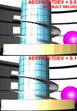
 between having
Dynamic tessellation on or off, you can definitely see the difference if you set the
Surface and Curve tessellations to their lowest values ( see images left ) and then Zoom
in and out a couple of times. The main function of Dynamic tessellation is to adjust
smoothness when changing proximity ( like Zooming ) to objects; hence the term
"dynamic". Static tessellation, the default when dynamic is off, never
changes smoothness or the number of tessellations and can thus prove to be faster when
working with tools like the 3D Orbit tool.
between having
Dynamic tessellation on or off, you can definitely see the difference if you set the
Surface and Curve tessellations to their lowest values ( see images left ) and then Zoom
in and out a couple of times. The main function of Dynamic tessellation is to adjust
smoothness when changing proximity ( like Zooming ) to objects; hence the term
"dynamic". Static tessellation, the default when dynamic is off, never
changes smoothness or the number of tessellations and can thus prove to be faster when
working with tools like the 3D Orbit tool.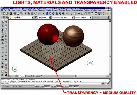
 Isolines
always on top - checking this box will display all isolines on 3D objects in
the two shademodes that have edges on - see illustration to the left.
Isolines
always on top - checking this box will display all isolines on 3D objects in
the two shademodes that have edges on - see illustration to the left. Once you have finished adding a Raster Plotter, you will find it in the Name
drop-down list on the Plot Device tab of the Plot and Pages
Setup dialogue boxes. Raster Plotters become .pc3 plot devices since no
real plotter actually exists for these formats and they are generally always output to a
File rather than a device.
Once you have finished adding a Raster Plotter, you will find it in the Name
drop-down list on the Plot Device tab of the Plot and Pages
Setup dialogue boxes. Raster Plotters become .pc3 plot devices since no
real plotter actually exists for these formats and they are generally always output to a
File rather than a device.