PART 6
LIGHT
Contents:
Light - Access ---- Lights dialogue box ---- Creating New Lights
---- Lights and Color ---- Lights
and Shadows ---- Modifying Lights ---- Customizing and Tricks
| Architectural
Desktop 3 - Presentation Guide PART 6 LIGHT Contents: |
| 1Light - Access | 1-6 LIGHT | ||||||||||||
How do I get this toolbar? You can also acquire access to these commands from the View pull-down menu. From the View pull-down menu, pick Render > and cascade to Light... |
 |
||||||||||||
| Render pull-down menu Illustrated to the right, I show the Render pull-down menu which consists of all the same tools as those found on the Render toolbar. In this Part we will be discussing what may prove to be the second most difficult aspect of the Rendering process: Lights. I place Materials above Lights since Lights are very limited but in other Rendering programs, such as Autodesk Viz, or 3D Studio Max, Lighting can be the most difficult part. Below, we will look at the three Light Types in AutoCAD and Architectural Desktop that you can use to create a 3-Dimensional quality to your Renderings. Light is something that we all recognize as being necessary for seeing our world and even in this program light is something ubiquitous. When you execute any of the Shademode options, for example, light is automatically added from a point behind and to the left of the observer ( screen ). This default Light can be changed by using the Lights discussed below. As with the Materials, more complexity in Lighting add to Rendering time and can often produce less attractive products than scenes Rendered with as little as one or two Lights. Night and Interior Lighting is of course the most difficult to set up in a realistic manner and it should be noted that AutoCAD and Architectural Desktop cannot produce lighting that bounces off of surfaces in the way Accurender and Lightscape can. This form of lighting is called radiosity and up until release four, even 3D Studio Viz was incapable of achieving this type of lighting without plug-ins. To achieve realistic lighting, you will have to become an artist with this tool and simulate how you think your Lighting really should look and do it within the limits of this program. |
 |
||||||||||||
| 2Lights dialogue box | 2-6 LIGHT | ||||||||||||
Lights dialogue box options broken down
The Lights dialogue box, illustrated to the right, is the primary tool for creating, modifying and managing Lights in AutoCAD and Architectural Desktop. There are only three Light Types: Point, Distant and Spot.
Modify... - this button will open the same dialogue box used to create a New light. Delete - this button will Erase the physical Light Block from your drawing and remove it from the Lights list. Select < - this button will allow you to access your drawing file to select a physical Light Block. This is a useful option if you cannot recall the Name and you need to Modify it. New... - this button creates a New light based on the Light Type selected on the New Light drop-down list ( Point Light, Distant Light or Spotlight ). Once you pick this button, you should be on a new dialogue box with numerous light settings. |
 |
||||||||||||
| North Location Illustrated to the right is the North Location dialogue box acquired from the North Location... button on the Lights dialogue box. If you intend to use this dialogue box, you must set the Angle prior to creating a Distant Light; changing the Angle after the creation of a Distant Light will have no effect on that light. You can use this dialogue box to change the default location of North based on the World Coordinate System (UCS) or any Named UCSs that you may have in your current drawing. Illustrated to the right, I show how you might change North by -90 degrees relative to the WCS. Though the dial indicates 90 degrees it really is -90 if we were to rotate an object on the screen. The effect of such a change, would alter our example Sun Light so that it would Rise and Set according to the new North. In other words, this is just like physically rotating your entire drawing by -90 degrees. For other UCSs, the Y-axis of the UCS becomes the new North. |
|
||||||||||||
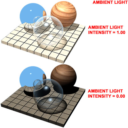
| Ambient Light - Intensity The Ambient Light scroll bar allows you to set the amount of ambient light in your current drawing between 0 (off) and 1.00 (100%). The Ambient Light control in AutoCAD and Architectural Desktop is similar to a brightness control in Photoshop. It illuminates everything everywhere equally and casts no shadows. Since the Rendering algorithm in AutoCAD and Architectural Desktop does not use radiosity, light calculations are finite and thus do not bounce off of objects to create a realistic ambient light. You can thus use the Ambient Light to make up for the missing light. As you introduce more Lights in a drawing, chances are that you will want to reduce the Ambient Light settings. In most cases, I find that using as little Ambient Light as possible produces the best looking results. However, Ambient Light settings have a significant impact upon the darkness of shadows so you may find that you use this option simply to control the outcome of shadows. |
 |
||||||||||||
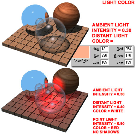
Ambient Light - Light Color
There are two ways to look at Color for Lights: as an actual color or as an intensity control. In other words, darker Colors produce less light. Since Ambient Light is usually used as a brightness control, using any other color than white seems counterproductive. If a Color is desired, it can be assigned to other lights. Using Color with any light tends to wash the entire scene, all objects and all materials, in a shade of that color. |
For late summer evening Renderings where there tends to be a reddish-orange glow to everything, you may first want to use a Background that is appropriate; if reflected on glass and other materials this can often produce enough of a glow to be convincing. See Light Color - Examples for more on the effects of Color on Lights. |
||||||||||||
| 3Creating New Lights | 3-6 LIGHT | ||||||||||||
| Creating Lights - Overview In my own experience rendering architectural projects, I have found that I am far more likely to use the Distant Light as a Sun for my first light than either of the other options. Even for interior work I may choose a Distant Light and turn off Roofs and Roof Slabs to get a quick sense of the work before spending a lot of time with interior lights. Below I will discuss the lights in the order that I have found them used in architectural renderings. |
 |
||||||||||||
Distant
Light
The New Distant Light dialogue box, illustrated to the right, offers a lot of options and settings that can be a bit overwhelming at first but many of these settings will be set automatically when you use the Sun Angle Calculator.
Intensity - this variable controls how strong your Distant Light will be in your rendering. The range is from 0 (off )to 1.00 (100%). This is a setting that plays a far more significant role with the other two Light types but if you use it for a Distant Light, it is similar to having a faint Sun; an evening sun perhaps. |
 Color - use the three Color scroll bars to set a Color or use either of the two Color buttons to select a unique color for this light. Using Colors, other than white, for lights can dramatically affect all objects in a Model. Darker Colors tend to reduce the Intensity of a Light. Read more about this under Lights and Color, below. Shadows - check the Shadow On checkbox if you wish for this Light to cast any shadows at all. Use the Shadow Options... button to choose between Shadow Volumes/ Ray Traced Shadows or Shadow Maps. Read more about this under Lights and Shadows, below. |
||||||||||||
| Distant Light - Sun Angle Calculator Illustrated to the right is the Sun Angle Calculator dialogue box acquired by picking on the Sun Angle Calculator... button on the New Distant Light or Modify Distant Light dialogue box. Though you can set everything you might need for accurate sun and shadow calculations here, I find that it is easier to use the Geographic Location... button first and then come back to set the Date, Clock Time, Time Zone and Daylight Savings ( if required ). By using the Geographic Location map first, you automatically acquire the Latitude and Longitude that affect where the Sun is at different dates and times of the year. Date - use the alphanumeric field to type a Date or use the adjacent scroll bar. Entry of Date must be in the form of "Month/Day". Clock Time - use the alphanumeric field to type a Time or use the adjacent scroll bar. Entry of Time must be in the form of "hour:minutes". The clock is base upon a 24-hour day so 12:00 is high noon and 24:00 is midnight. Time Zone - use the drop-down list to indicate what time zone the Rendering project is in. This will not be calculated by the Geographic Calculator so you will have to specify it. Since time zone measurements change, the list is not up to date and you may have to compensate by adding or subtracting hours to the closest option. You can check http://greenwichmeantime.com/local/europe/ for European time zone information. Daylight Savings - most countries are on daylight savings in the winter but not in the summer. |
 Latitude and Longitude - use the numeric field to type in exact global coordinates relative to the hemisphere your project is in or use the adjacent scroll bars. Using the Geographic Location dialogue box can make this much easier. Hemisphere - use the North/South and East/West drop-down lists to designate the hemisphere of the globe your project is in. Using the Geographic Location dialogue box can make this much easier. |
||||||||||||
| Distant Light - Geographic Location Illustrated to the right is the Geographic Location dialogue box acquired by picking on the Geographic Location... button on the Sun Angle Calculator dialogue box ( discussed above ). On the Continent drop-down list, located to the left of the Nearest Big City check box, you can change the map to all other continents on the planet. Nearest City - when checked, you will automatically be positioned near a major city when you pick on the map. When unchecked, you can pick anywhere on the map and expect to find the closest Latitude and Longitude to where you pick instead of the Latitude and Longitude of the nearest major city. You can fine-tune this position, if required, back on the Sun Angle Calculator dialogue box. City - you can use this drop-down list to select a Big City in the continent set on the Continent drop-down list. Cities on this list will also be selected when you pick on the graphic map; provided the Nearest Big City checkbox is checked. Latitude and Longitude - if you know the exact location of your project, you can uncheck Nearest Big City and type in the Latitude and Longitude. |
 |
||||||||||||
| Distant Light - Physical Location Once you have done all of the hard work figuring out the the Geographic Location, Date, Time, Shadows, Color and Intensity and hit the last OK button, you may wonder about the actual location of your Distant Light object in your drawing. The Distant Light Block will automatically center itself on Z-axis origin of the Current UCS relative to the WCS. In other words, it will be centered on a line from the UCSs origin. The rotation of the Current UCS will not affect the angle of the Distant Light since all of that information is calculate relative to the ground plane as established by the World Coordinate System. |
At times, this means that the Distant Light object is located on the ground and often inside a part of your Model. If this occurs, you can safely Move a Distant Light Block around in a drawing without changing the calculations and angle of the light. This means that you can Move the Light up or down or around horizontally but you cannot Rotate it since that will affect the calculated accuracy and may no longer represent a real sun. |
||||||||||||
Point
Light
The New Point Light dialogue box, illustrated to the right, offers a basic set of options including Name, Position, Color, Attenuation and Shadows. A Point Light is most like a light bulb but actually more like a sphere of light. This description would make most people choose it for a Sun but the problem with using this type of Light for a Sun, is how the Shadows cast from objects. Point Lights do not cast parallel rays of Shadow so that is why it is better to think of this Light type as a bare bulb.
Intensity - this variable controls how strong your Point Light will be in your rendering. There are three ranges based on the Attenuation setting: None is from 0 (off )to 1.00 (100%), Inverse Linear and Inverse Square is from 0 to a huge number derived from the physical Extents of your current drawing. Since AutoCAD and Architectural Desktop default to about the middle of the scale on the Intensity for each of the Attenuation options, you may find them all too bright. Modify < - use this button to position your Point Light in your drawing. Think of this process just like inserting a Block; you will need to specify X, Y and Z coordinates. The easiest way to do this is to OSNAP to some object that has been drawn at the exact position where you want to place your Point Light. You can also OSNAP to a point on the ground and later use the Move command to bring the Point Light up or down along the Z-axis as needed. Show... - this button simply displays the coordinates for the Location of your Point Light. The Target coordinates are irrelevant on Point Lights since they don't have direction but Spot Lights do. Color - use the three Color scroll bars to set a Color or use either of the two Color buttons to select a unique color for this light. Using Colors, other than white, for lights can dramatically affect all objects in a Model. Darker Colors tend to reduce the Intensity of a Light. Read more about this under Lights and Color, below. |
Attenuation - there are three
choices for the type of light degradation you want: None, Inverse Linear and Inverse
Square. Shadows - check the Shadow On checkbox if you wish for this Light to cast any shadows at all. Use the Shadow Options... button to choose between Shadow Volumes/ Ray Traced Shadows or Shadow Maps. Read more about this under Lights and Shadows, below. |
||||||||||||
Spotlight
The New Spotlight dialogue box, illustrated to the right, offers all of the same options as the New Point Light but with some very practical direction controls. A Spotlight is most like a recessed ceiling light or street lamp because it is directional and can produce a cone of light.
Intensity - this variable controls how strong your Spotlight will be in your rendering. There are three ranges based on the Attenuation setting: None is from 0 (off )to 1.00 (100%), Inverse Linear and Inverse Square is from 0 to a huge number derived from the physical Extents of your current drawing. Since AutoCAD and Architectural Desktop default to about the middle of the scale on the Intensity for each of the Attenuation options, you may find them all too bright. Modify < - use this button to position your Spotlight's Location and Target in your drawing. Think of this process just like drawing a line based on an origin and endpoint in 3D Space. The easiest way to do this with best results is to OSNAP to some existing points in your drawing, something like a line or other objects that define the Target and Location. Doing this in an Isometric View is preferable since you will have to specify two points instead of one. If you don't get the points right the first time, you can use the Modify Light button to come back to this dialogue box and reset the points. Show... - this button simply displays the coordinates for the Location and Target of your Spotlight. This option is very useful for the Spotlights because you can quickly check to see if you were successful at selecting unique Z-axis values for your Location and Target ( depending upon the orientation of the UCS icon, it could also be the X or Y-axis ). Color - use the three Color scroll bars to set a Color or use either of the two Color buttons to select a unique color for this light. Using Colors, other than white, for lights can dramatically affect all objects in a Model. Darker Colors tend to reduce the Intensity of a Light. Read more about this under Lights and Color, below. Hotspot - use this option to set an Angle between 0 and 160 degrees for the primary cone of light emanating from your Spotlight towards the Target. The Hotspot represents the area where the Spotlight will be the brightest on the target. |
Falloff - use this option to set an Angle between 0 and 160 degrees for the secondary cone of light emanating from your Spotlight towards the Target. The Falloff represents the area where the Spotlight go from the brightest ( Hotspot ) to the weakest. You can think of the Hotspot and Falloff as concentric cones where the Hotspot is the inner brighter area and the Falloff is everything from the inner cone to the outer cone. Attenuation - there are three
choices for the type of light falloff you want: None, Inverse Linear and Inverse
Square. Shadows - check the Shadow On checkbox if you wish for this Light to cast any shadows at all. Use the Shadow Options... button to choose between Shadow Volumes/ Ray Traced Shadows or Shadow Maps. Read more about this under Lights and Shadows, below. |
||||||||||||
| 4 Lights and Color | 4-6 LIGHT | ||||||||||||
Light
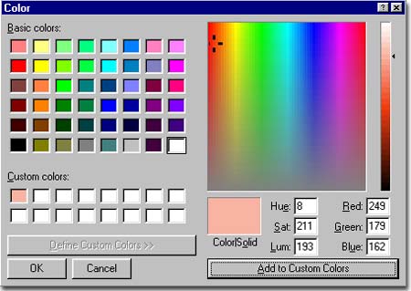
Color
Every Light type in AutoCAD and Architectural Desktop has the option for Color assignment, even the Ambient Light. For each Light type there are two dialogue boxes to choose from when adjusting a Light's Color: the True Color dialogue box, illustrated to the right, and the AutoCAD Color Index (ACI) used inside AutoCAD and Architectural Desktop for such tasks as setting Layer Colors ( 255 Colors only ). Illustrated to the right, on the True Color dialogue box, is an example of a trick you might use for an Evening Sun that creates a slight hue of red-orange in your Rendering. If you experiment with this trick, you will most likely want to use a very light shade because not only are darker shades a way of decreasing the intensity of a light, but heavy hues have a dramatic effect on a rendering; i.e., it's very easy to create a Mars-like effect for any rendering. White is usually the best choice for most lights. When using True Colors confirm that your Renderings are being produced with True Color capability in your drawing - see Display tab of Options dialogue box. |
 |
||||||||||||
| Light Color - Examples Illustrated to the right, I show two examples of how Color can affect a Rendering scene. You can compare these images with those at the beginning of this Part to see the difference between white light and these two shades of red. On the top right example, a Distant Light ( Sun ) was assigned a slight amount of reddish-orange True Color as a Sun might appear in a late evening. The effect is a hue upon all objects and materials except the Chrome. This material has been set to reflect a specific Background Color and thus does not reflect the hue. A Background image or Color would be required to make the full effect more believable. The Sunset.tga bitmap would work well as a Background Image file. The reddish-orange color can also be used to produce a warmer glow as can be seen on the tile and wood materials. On the bottom right example, the Distant Light ( Sun ) was reset to use a White Color but its Intensity was reduced to allow another Light to appear more bright. A Point Light ( Bulb ) was added in the center and given a primary Red Color to illustrate how other Lights can affect a scene. To avoid producing a Red washout, the Point Light was set to produce no Shadows and all Attenuation was turned off. This allows for a very simple control over the Intensity ( brightness ) of the light allowing the primary Light source, the Distant Light, to create the falloff and shadow effects. The biggest problem with Lights that appear in a scene such as this one, is actually making the source believable. Since the source produces no special glow like real fixtures, you may have to improvise and be very creative. Ultimately, a bit of Post Rendering work with Photoshop may be the only way to create a believable effect. Most simply use a White object or White Material ( as bright as possible ) to act as the source of a Light or Lights. |
 |
||||||||||||
| 5Lights and Shadows | 5-6 LIGHT | ||||||||||||
Light
Shadow Options
There are basically two types of Shadows for all three Lights; with the exception of how Ray Traced Shadows act as Shadow Volumes when the Photo Real Rendering Type is used. In other words, since Ray Traced Shadows require Photo Raytrace to be the rendering type used, you won't get Ray Traced Shadows when you use the inferior Photo Real rendering type. Shadow Volumes/Ray Traced Shadows - use this checkbox to set a mathematical method for producing shadows. These tend to be hard crisp edged shadows often associated with computer renderings. Checking this option deactivates the Shadow Map method and its associated settings. Photo Real will use Shadow Volumes and Photo Raytrace will use Ray Traced Shadows. In my personal experience, I have found Ray Traced Shadows look better and can actually be Rendered more quickly. |
See Photo Real Rendering More... Options dialogue box for how to create better Shadow Map shadows. Shadow Maps - unchecking the Shadow Volume/Ray Traced Shadows defaults the shadow to be produced by a map of the objects in your drawing that is placed on the ground as a silhouette. This method is not as accurate as the Ray Traced shadows and often leaves out details such as holes between branches. Though the method is not as accurate, it can produce softer effects. The time factor can actually be increased due to demand on your system's RAM where the Shadow Maps are created and stored. Colors of transparent objects do not show in these shadows. Shadow Map Size - this drop-down list provides a pixel number range between 64 and 4096. By using more pixels the map becomes more accurate and more like a raytraced shadow but at the cost of rendering time. Shadow Softness - this option offers a range between 1 and 10 where 1 is the most crisp and 10 is the most soft. The higher the number of pixels for the Shadow Map Size the less fuzzy the Shadow Softness will appear ( even at a value of 10 ). Shadow Bounding Objects < - use this button to select the object or objects that you want to cast shadows based upon Shadow Maps. By using this option, you can actually create lights that only cast shadows off of specific objects. If this option has not been used, all objects will cast shadows. Once this button has been used, only the object(s) selected will cast shadows until more objects have been added. Keep in mind that this affects only the current light. |
||||||||||||
| 6Modifying Lights | 6-6 LIGHT | ||||||||||||
| Modify Lights - Overview With Lights you will need to think of them as having two types of Modification: Settings and Physical position. This means that you can use the Light dialogue box to make Light behavioral changes but that you can also use the basic AutoCAD editing commands to change the physical location. Since Lights are Blocks, you can almost work with them as you would with any Blocks. The one significant difference has to do with the Light Names which need to be unique for every single Light in order to function at all. Modifying Distant Lights that are being used for true Sun Angle Calculations, should not be Rotated but Moving them on Plan or Elevation Views is okay. Read Distant Light - Physical Location for more information. |
 |
||||||||||||
Modify
Light Settings
To Modify a Light, you use the Lights dialogue box as illustrated to the right. When you want to make changes to a Light, you Select or Highlight it in the Lights list and then use the Modify... button to access the same dialogue box that was used to create it. This means that all of the settings for creating a New Light apply to Modifying one - see comments for Creating New Lights above. If you want to Modify a Light in your project drawing but cannot remember its Name, you can use the Select< button to temporarily exit the Lights dialogue box to use your cursor to physically select it. Once you have selected a physical light object, the Lights dialogue box will reappear and you can then use the Modify... button to make your changes.
|
 |
||||||||||||
Modify Lights Graphically
The Light Blocks are controlled by the Light Icon Scale setting found on the Render and Render Preferences dialogue boxes. For architectural projects, the default scale of 1 is often far too small to be seen. This setting can be changed at any time during your project and can be changed up and down as many times as you like. All existing Light Blocks are automatically rescaled according to the latest Scale value. The Scale of the Icon has no effect upon the Light Settings so a larger Icon Scale does not equate to more Light. You can change the Light Icon Scale on both the Render and the Render Preferences dialogue boxes but since the Render dialogue box does not save setting changes unless you actually start the Rendering process, the Render Preferences dialogue box illustrated to the right, is a better choice. |
Choosing the "right" Light Icon Scale is really a matter of personal taste. I find that I like them large when I am focusing on Lights and smaller when I am working on other problems. If in doubt, try using the output scale for printing; something like 48 or 96 for 1/4" = 1'-0" or 1/8" = 1'-0" or 100 for 1m = 100m. |
||||||||||||
| Modify Lights Physically Since Lights are managed as physical Blocks in your drawing, there are a few things that you can do with those objects by using regular AutoCAD editing commands. Move - one of the most common problems with placing Lights is getting them at the right location. At times, it is easy enough to get them located correctly in Plan ( top ) View only to discover that they are on the ground. By using the Move command and setting an appropriate UCS axis rotation, you can make short work of Moving a Light up or down in a drawing. Copy - one of the most natural tendencies for users of AutoCAD and Architectural Desktop is to use the Copy command to create many Lights in a drawing. When Rendering Copied Lights, you may discover that only one Renders and this is because the Lights all have the same Light Name. This means that it is okay to Copy Lights, but you must remember to use the Lights dialogue box to Rename them. To do this, use the Modify... button and simply specify a unique name for each Copied Light. This is why many use numbers for their Lights; then, all you have to do is change each number in succession. Erase / Delete - when you Erase or Delete a Light it is removed from the Lights dialogue box and thus no longer exists. The result is thus identical to using the Delete button on the Lights dialogue box. Rotate - both the Distant Light ( Sun ) and Spotlight ( Lamp ) are directional so rotating them will have an effect upon the direction of the light they emit. The Point Light ( Omni ), on the other hand, emits light spherically and thus Rotating it only affects the Block and its attribute but not the Light it emits. Block / Wblock - if you plan to create objects, such as light fixtures, with Lights preset in them and use them as Blocks, there are a couple of problems to deal with. Since a Light object is a Block, Re-Blocking or Nesting makes this object unreadable within the Light dialogue box and thus you will need to Explode your Block in order to have the Light or Lights function properly. If you Copy the Block or place multiple Insertions of the Block in a drawing, all will have to be exploded and then the Lights within each Copy will have to be Renamed ( see comments under Copy, above ). Don't be discouraged by these limits however since creating a desk lamp, for example, with a unique Light Name is a very valid solution. If you intend to use the block extensively for Rendering purposes, you might consider double-Blocking it so that you can explode it once to release the Light while keeping the object intact as a Block - just don't use the same Name in the Nested Block. Attribute Editing - though the Light objects are Blocks with Attributes, you cannot edit the Attributes and expect proper changes to occur in the Light dialogue box. The Lights reside on the ASHADE Layer which is routinely Locked in your drawing to prevent this type of editing mistake. |
 |
||||||||||||
| 7Customizing and Tricks | 7-6 LIGHT | ||||||||||||
| Lights that look like lights When working with lamps, you may find that the light source does not show up in your Rendering. Typically in Rendering software light calculations are done base upon what they strike so there will be no evidence of an origin unless a physical object catches the light near the source. There are Post Rendering tricks that can be used, like Lens Flare in Viz or Photoshop but in AutoCAD and Architectural Desktop no such special effects exist. The solution is to create a Source for the Light without affecting the light and shadows being cast by the light. To have it both ways, you will need to use two lights. One will act as the generator of the way you want the light emitted and the shadows cast while the other acts as the source of the light itself. Illustrated to the right, I show a common industrial type hanging lamp with a wire grill beneath it. In the center, I have create a small sphere and Attached the White Glass Material from the default Materials Library. Inside this sphere, I have placed a Point Light with very low Intensity, Inverse Square Attenuation ( to make it fall off quickly ) and No Shadows. By working with this Point Lights Intensity Value, I can make the bulb appear dull or bright - as illustrated to the right. Also illustrated to the right is the second Light, a Spotlight that has been positioned as you would expect the light to behave from such a lamp. It has been placed below the sphere to avoid being affected by this object but has been placed slightly above the wire grill - as is illustrated by the strong shadow lines, upper right. If I do not wish to have the wire grill shadows in my Rendering, I can simply Move the Spotlight down below this object or even turn the Layer of this object off. Efforts like this are not typical and should not be done on every lamp because the Rendering time increases with all of the extra detail. Knowing when to do the extra work to make the Rendering Scene more believable is a mater of artistry. |
 |
© Copyright 2002 ARCHIdigm. All rights reserved.
spell checked on Jan. 24, 2002
 Lights: - this list shows all physical lights in
the current drawing. Since lights are tracked as Blocks with Attributes, they are
physical objects in your drawing. Copying and Erasing them will affect the Lights
list accordingly.
Lights: - this list shows all physical lights in
the current drawing. Since lights are tracked as Blocks with Attributes, they are
physical objects in your drawing. Copying and Erasing them will affect the Lights
list accordingly.
 Light Name:
- you must specify a unique name for your light and you are limited to eight characters,
no spaces and no wild characters such as "/" , "*", etc. In the
illustration to the right, I show that I have named my example Sun "S_6-21_N"
to indicate that the Light is a Sun, set to the date of June ( 6
) 21st at 12:00 Noon. Using this technique, I can
have another Distant Light acting as an Evening Sun in January, for example, and be able
to set Scenes for these different times of the year.
Light Name:
- you must specify a unique name for your light and you are limited to eight characters,
no spaces and no wild characters such as "/" , "*", etc. In the
illustration to the right, I show that I have named my example Sun "S_6-21_N"
to indicate that the Light is a Sun, set to the date of June ( 6
) 21st at 12:00 Noon. Using this technique, I can
have another Distant Light acting as an Evening Sun in January, for example, and be able
to set Scenes for these different times of the year.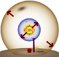 Light Name: - you must specify a unique name for
your light and you are limited to eight characters, no spaces and no wild characters such
as "/" , "*", etc. In the illustration to the right, I show that
I have named my example Bulb "Omni_1" to indicate that the
Light is a Point Light that produces light in all directions and that it
is one among several in my drawing. Using this technique, I can have another Point Light
called Omni_2, Omni_3 and so on. You can, of course, get more elaborate in the name
and specify a more exact function. I recommend more descriptive names when using a
lot of lights. I use numbers because when you Copy Lights,
they don't work unless you rename them to something unique.
Light Name: - you must specify a unique name for
your light and you are limited to eight characters, no spaces and no wild characters such
as "/" , "*", etc. In the illustration to the right, I show that
I have named my example Bulb "Omni_1" to indicate that the
Light is a Point Light that produces light in all directions and that it
is one among several in my drawing. Using this technique, I can have another Point Light
called Omni_2, Omni_3 and so on. You can, of course, get more elaborate in the name
and specify a more exact function. I recommend more descriptive names when using a
lot of lights. I use numbers because when you Copy Lights,
they don't work unless you rename them to something unique.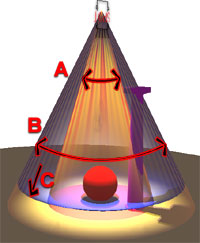 Light Name: - you must specify a unique name for
your light and you are limited to eight characters, no spaces and no wild characters such
as "/" , "*", etc. In the illustration to the right, I show that
I have named my example Lamp "Lamp_A_1" to indicate that the
Light is a Spotlight with direction and Falloff. Using this
technique, I can have another Spotlight called Lamp_A_7, Lamp_B_3 and so on. You
can, of course, get more elaborate in the name and specify a more exact function. I
recommend more descriptive names when using a lot of lights. I
use numbers because when you Copy Lights, they don't work unless you rename them to
something unique.
Light Name: - you must specify a unique name for
your light and you are limited to eight characters, no spaces and no wild characters such
as "/" , "*", etc. In the illustration to the right, I show that
I have named my example Lamp "Lamp_A_1" to indicate that the
Light is a Spotlight with direction and Falloff. Using this
technique, I can have another Spotlight called Lamp_A_7, Lamp_B_3 and so on. You
can, of course, get more elaborate in the name and specify a more exact function. I
recommend more descriptive names when using a lot of lights. I
use numbers because when you Copy Lights, they don't work unless you rename them to
something unique.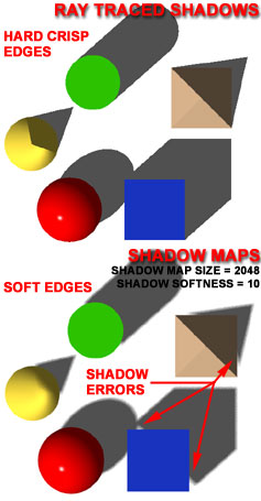 Illustrated to the right
is the Shadow Options dialogue box accessed from the Shadow
Options... button on the New or Modify Light dialogue
box.
Illustrated to the right
is the Shadow Options dialogue box accessed from the Shadow
Options... button on the New or Modify Light dialogue
box.