PART 2
SHADEContents:
Shade - Access ---- Shademodes ---- Shademodes with Rendering ---- Variables and Settings that Affect Geometry when Shaded ---- Customizing and Tricks
| Architectural
Desktop 3 - Presentation Guide PART 2 SHADEContents: Shade - Access ---- Shademodes ---- Shademodes with Rendering ---- Variables and Settings that Affect Geometry when Shaded ---- Customizing and Tricks |
| 1Shade - Access | 1-2 SHADE | ||||||||||||
| Shade toolbar How do I get this toolbar? You can also acquire access to these commands from the View pull-down menu. From the View pull-down menu, pick Shade > and cascade to a desired Shade Mode. |
 |
||||||||||||
Shade pull-down menu
Illustrated to the right, is the View pull-down menu showing the Shade cascading menu. There are seven Shademodes to choose from and they are accessible through the Shade toolbar, View pull-down menu, 3D Orbit pop-up menu and the typed "Shademode" system variable. Once you activate any Shademode other than 2D Wireframe, your graphics display will behave a little differently than when in normal 2D Wireframe mode. Depending upon the configuration and hardware of your computer, you may notice such anomalies as linework disappearing when being drawn or the lack of "dragmode" highlighting when objects are being Moved, Rotated or Stretched. If you experience any unusual graphic behavior while working in a Shaded mode, be sure to reset 2D Wireframe before working on other system settings.
|
 In other situations, particularly with large models, I have found that I need to set the Shademode to 2D Wireframe, use any of the View directions to switch out of the current view and then reset my desired Shademode and View. The performance of Shademode can be considerably affected by the settings on the the 3D Graphics System Configuration dialogue box accessed through the Properties... button on the System tab of the Options dialogue box. Below, we will discuss some of these settings. |
||||||||||||
| 2Shademodes | 2-2 SHADE | ||||||||||||
2D Wireframe and 3D Wireframe
2D Wireframe is the normal default mode we work in most of the time and is basically the equivalent of an Off switch for Shademode. In 2D Wireframe, you will see all of the lines everywhere as long as other system variables, such as Isolines, have been set to show lines on 3D Objects. 3D Wireframe is an odd duck in this mix and is still a mystery to me. As I see it, it is the equivalent of 2D Wireframe for the 3D Orbit tool and seems to be the first in a series of true Shademodes. Once activated, the 3D Shaded UCS icon appears and any settings from the last session with the 3D Orbit tool are applied. The Color of Material Attachments can display. |
 |
||||||||||||
Hide & Hidden
Hide is an old AutoCAD command for removing the lines of 3D objects that are behind faces of other 3D objects ( Hidden Line Removal ). This command is not part of the Shademode system variable but still has some practical uses despite it slow operation and inability to remain while changing the view. Illustrated lower right, I show how you can use the Hide command when Plotting a Viewport on a Layout. By selecting a Viewport Frame, right-clicking to access the object-specific pop-up menu, you can use the Hide Plot menu item to activate Hidden Line Removal of the objects in the current Viewport upon Plotting. Hidden Line Removal will also occur on Plot Previews. This is the only plotable and printable display option among the group being discussed in this part. The various Shademodes cannot be plotted nor exported in any fashion ( not even with WMFOUT ). Hidden is much like the other Shademode options but produces no shading. When activated, this Shademode remains active until Shademode has been changed even when activating the 3D Orbit tool. This display type is generated much faster than what the Hide command produces but, as with the other Shademodes, cannot be plotted or printed. |
|
||||||||||||
Flat and Flat with Edges On
Flat Shaded shades according to the triangular polygon faces that define the 3D Objects and is the equivalent of a shaded version of what the Hide command produces. This option runs faster but looks flat and jagged. Flat Shaded with Edges On is the same as Flat Shaded but with object edges on top. This option tends to bring out definition, especially in small or distant objects but can produce odd geometry up close where the edges appear distant from the shading. Edge Color is based on the object's color or the Color of the Material Attached to it ( takes precedence over object color ). |
 |
||||||||||||
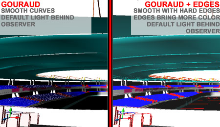
Gouraud and Gouraud with Edges On
Gouraud Shaded smoothes the edges between the triangular polygon faces that you see with Flat Shaded and Hide. This produces a more realistic impression of curved surfaces but takes more time to display. Gouraud Shaded with Edges On is the same as Gouraud Shaded but with object edges on top. As with the Flat Shaded with Edges On option, this option brings out definition of geometry that is small or far away. Edge Color is based on the object's color or the Color of the Material Attached to it ( takes precedence over object color ). |
 |
||||||||||||
| Shade
command This command defaults to the Shademode "Flat Shaded, Edges On" and cannot be set to default to other settings. |
|||||||||||||
| 3Shademodes with Rendering | 3-2 SHADE | ||||||||||||
Shademode and 3D Graphics Display
This means that at any point in the design and construction document phase, you can work with Materials, Lights and/or Landscape Objects displayed to better see and better communicate the design. |
 Illustrated to the above, I show a few materials applied to a concept commercial building that is in the Pre-Design phase where some Mass Elements have been converted Boundaries and where some Boundaries have been Converted to Walls with Doors and Windows. |
||||||||||||
| Shading
with Lights When you use either the Flat or Gouraud Shademodes, the light is automatically calculated from a source behind and slightly to the left of the viewers head. If you have assigned any lights in the current drawing or simply want to control the level of the default Light, you can use the Light dialogue box on the Render toolbar and then activate this new Light source on the 3D Graphics System Configuration dialogue box ( see image above ). In the illustrations to the right, I show how different a Shaded Model can look on screen when the Lights are Enabled. The two Shaded images can be identical if the position of the New Light is matched to that of the default Light source. If the New Light is dark or on the opposite side of the viewing angle then the Shaded image will appear dark. You can adjust the Light and/or adjust the Ambient Light Intensity to lighten the Shaded image. Since you are likely to move around a design and view it regularly from various angles, it is probably best to use the default Light Source since it moves with the viewing angle and always maintains the same level of intensity. |
 |
||||||||||||
| Shading
with Materials When you use either the Flat or Gouraud Shademodes, you can activate the Material Colors Attached to any objects in your Model. Material Colors are derived from the Color/Pattern Attribute. Many Materials that use bitmaps for texture also use the bitmap image for Color and thus you may find that these Materials do not show a Color or show a dark color rather than what you might expect. When you "Enable materials" Material Transparency is automatically enabled. This means that Materials such as Glass will be semi-opaque when Shaded - see also comments below on transparency. |
 |
||||||||||||
| Shading with Textures and Transparency When you use either the Flat or Gouraud Shademodes, you can activate the Material Textures as a subset of Materials and thus be able to see not only the true Colors of the Materials but also any textures. Activating this option actually attempts to display the bitmap as it has been Attached and Mapped to your objects. Depending upon your system configuration and the size of your Model, some bitmap images may not display at all or display with strange distortions.
|
Perspective views tend to produce the worst distortions in Material Textures while Elevations and Isometric Views produce the best results. The appearance of Materials in Flat and Gouraud Shademodes is only an approximation of what the actual Rendering will look like and should not be used as a true gauge of position, size, color and bumpiness of the final Rendered image. In other words, Render to see it Rendered. In addition to Material Texture, you will also see Material Transparency. There are three options for controlling the display of Material Transparency: "High Quality/Slower, "Medium Quality" and "Low Quality/Faster". Though the High Quality/Slower may sound like the best in this group, I find that I prefer the look of Medium because of how glazing is pixilated as opposed to nearly perfectly transparent. The primary visible difference between Medium and Low Quality Transparency has to do with the number of pixels. Low Quality may also prove to be good enough to provide an impression of glazing and the difference in system performance can easily be felt on systems that are already taxed by all of the other things it has to display. |
||||||||||||
| 4Variables and Settings that Affect Geometry When Shaded | 4-2 SHADE | ||||||||||||
Facets
and Edges
In AutoCAD and Architectural Desktop there are all sorts of strange Display settings and variables that you can change to affect the way objects appear on your screen, when printed and when Rendered. You can read about most of them in the Appendix under the topic of "Options dialogue box". For the various Shademodes, there are some that affect objects in unique ways. Shadedif and Shadedge - these two variables no longer appear to have any noticeable effects on shading or rendering. Shadedif was a control for diffuse light and shadedge was a control for how the edges were displayed. Though the variables still exist they seem ineffective. Viewres ( 1 - 20000 ) - this system variable has no direct impact on Shaded objects but does have a direct impact on Rendered objects. The higher the value, the smoother the objects. AecObjects are unaffected in both cases. For 2D Wireframe and Renderings, Arc, Circles and other curves are directly affected by the value of Viewres ( the higher the smoother ) - this includes Surfaces and objects with Thickness values. Solid object smoothness is controlled directly through the Facetres system variable but when set to one ( 1 ) this variable matches in a one-to-one relationship, the value of the Viewres. This means that Viewres can affect the smoothness of Solid objects. |
Facetres ( .01 - 10 ) - Solids - this system variable controls the smoothness of 3D Solid objects in Shademodes and Renderings. The higher the value the greater the facets as multiplied by the current Viewres value. It also affect the faceting of Solid objects when exporting to other programs. When set to one ( 1 ), it matches the value of the Viewres system variable. When set to higher or lower values, the affect is a multiple of the current Viewres value. AecFacetdev ( also called Facetdev ) ( >0 - infinity ) - AecObjects - this system variable controls the smoothness of AecObjects ( created by Architectural Desktop ) in 2D Wireframe, Shademodes and Renderings. The lower the value the smoother or faceted the surfaces. This is because this variable works on the deviation principal measuring the chord length of a curve: smaller value = shorter distances and more facets. Isolines ( 0 - 2047 ) - Solids - this system variable controls the number of tessellations on 3D Solid objects when viewed in 2D Wireframe only. Surftab1 and Surftab2 ( 2 - 32766 ) - Surfaces - these system variables control the number of tabulations ( could be called tessellations too ) on the Rulesurf, Tabsurf, Edgesurf and Revsurf tools in 2D Wireframe, Shademodes and Rendering. Surftab2 only affects the Edgesurf and Revsurf by setting the number of tabulations for the Y portion of a grid. These variables must be set prior to object creation; changing the variables after object creation has not effect upon existing object smoothness. Lights - the automatic background light that is used when using the solid Shademodes cannot be changed but if the AcRender.Arx application has been loaded, the light can be controlled with the Ambient Light Value on the Lights dialogue box. The default Light can also be deactivated by using the Enable Lights option on the 3D Graphics System Configuration dialogue box. Display Configurations - there are other settings at the driver level of your system that can also be used to affect the appearance of shaded objects. These settings can control smoothness, materials, lights, textures and overall performance of you computer and display - read more under Options - System tab - 3D Graphics System Configuration. |
||||||||||||
| 5Customizing and Tricks | 5-2 SHADE | ||||||||||||
| Printing Shaded Views Since Shaded Views cannot be printed you will have to come up with some clever tricks to get those great looking images onto paper or digital media. My primary trick is to use the Prnt+Scrn keys in combination with Photoshop. The other trick is to Render the work to a File and this can be achieved with a few simple steps that I will outline below. The primary problem with the switch between a Shademode and the Render dialogue box is that Lights and Materials automatically change. Once the AcRender.ARX application has been triggered, Shaded objects can loose a lot of that plastic luster they exhibit ( especially with the Gouraud Shademode ). This means that you either unload the AcRender.ARX application every time you want to the default look of the shademodes or you build a Material and a Light that can recreate the same look. Illustrated to the right I show the steps required to create a single Material that can be Attached to all 3D objects so they will look like they are Gouraud shaded on screen and when Rendered. This will allow you to produce Renderings that look very similar to the default Gouraud shademode that you see on screen. Gouraud Material for Global use On the Modify Standard Material dialogue box, illustrated right, I show that I have created a New Material that I Named "Gouraud"and set the Color/Pattern Attribute's Color to "By ACI". This will automatically use the AutoCAD Color Index to determine the objects' colors. For the Value of this Material, I show that I have set it to about 80% ( 0.83 to be exact ) because I want a Color close to the ACI but a little weaker leaving variation for Ambient and Reflection Values. |
 |
||||||||||||
| For the Ambient
Attribute, I show that I have Locked its Color
to that of the Color/Pattern Attribute and set the Value to the 0.83.
On this Attribute it would be nice to choose another Color for the darker parts of
the objects but since every object may have a different Color this has to be set to either
By ACI or Lock ( which is safer ). For the Reflection Attribute, I show that I have changed the Color to pure White and set the Value to 1.00. This setting controls the highlight color and thus I want to use a bright white to match the default Gouraud Shademode. For the Roughness Attribute, I show that I have set the Value to about 70% ( 0.67 to be exact ). This Value controls the smoothness of the Material and by using the Preview button you can gauge for yourself what looks about right. A lower value makes a more plastic look while a higher value produces a more flat look. There is no need to modify the remaining Attributes. When choosing a method for Attachment, the Direct ( by using the <Attach button ) method is the fastest but also the least flexible. The Attachment methods have a hierarchy where direct overrides any other forms; *Global* is the default Attachment, then comes By Layer, By ACI and then by Attach. If you want to work with other Materials, choose a weaker Attachment type or use the steps described here for the *Global* Material and you will not have to worry about hierarchies or Attachments. Add a Distant Light Render to File |
 |
||||||||||||
© Copyright 2002 ARCHIdigm. All rights reserved.
spell checked on Jan. 20, 2002
 When working in Shaded modes using Architectural
Desktop you may find that when you change the View, objects sometimes do not
display properly or at all. This graphic phenomena is more common on machines with
lower end graphics cards. To reset this graphics display problem, you can use any of
the Display Configurations ( illustrated, left ) to switch out of the
current display setting and then switch back.
When working in Shaded modes using Architectural
Desktop you may find that when you change the View, objects sometimes do not
display properly or at all. This graphic phenomena is more common on machines with
lower end graphics cards. To reset this graphics display problem, you can use any of
the Display Configurations ( illustrated, left ) to switch out of the
current display setting and then switch back.
 One of the most exciting new features that came with AutoCAD 2000
was the ability to modify the Display Driver Settings for improved performance or improved
graphics. For the various Shademode options, you can actually work with Materials,
Lights and Landscape Objects displayed as illustrated to the right.
One of the most exciting new features that came with AutoCAD 2000
was the ability to modify the Display Driver Settings for improved performance or improved
graphics. For the various Shademode options, you can actually work with Materials,
Lights and Landscape Objects displayed as illustrated to the right.