PART 10
SCENESContents:
Scenes - Access ---- Scenes dialogue box ---- Scene Preparation ---- Create and Render a New Scene ---- Customizing and Tricks
| Architectural
Desktop 3 - Presentation Guide PART 10 SCENESContents: Scenes - Access ---- Scenes dialogue box ---- Scene Preparation ---- Create and Render a New Scene ---- Customizing and Tricks |
| 1Scenes - Access | 1-10 SCENES | ||||||||||
How do I get this toolbar? You can also acquire access to these commands from the View pull-down menu. From the View pull-down menu, pick Render > and cascade to Scene... |
 |
||||||||||
| Render pull-down menu Illustrated to the right, I show the Render pull-down menu which consists of all the same tools as those found on the Render toolbar. In this Part we will be discussing Scenes and how they are used for Renderings. The Scene dialogue box consists of two components, Saved Views and Lights but the concept of a scene goes way beyond that and into the whole process of preparing a Rendering. Below, we will not only look at the Scene dialogue box and how it can be used to quickly switch from one set of lights to another but we will also go through the process of preparing a project for Rendering. You can use this discussion as a review of all the other Parts or as a starting point for one of your first Rendering projects. The example file used to demonstrate the various dialogue boxes, concepts and results is available for downloading so you can follow along or simply express your own creative concepts on one of the most well known works of Modern architecture, the Barcelona Pavilion -> Part - X - Downloads If this building proves to be as interesting a learning tool for you as it was a teaching tool for me, you can actually go and visit it in Barcelona, Spain. It has been reconstructed to original specifications and I can't believe that I missed it when I was there in the summer of 2001. For more information on this building visit this website ->http://www.miesbcn.com/ |
 |
||||||||||
| 2Scenes dialogue box | 2-10 SCENES | ||||||||||
Scenes dialogue box options broken down
The Scene to Render list on the Render dialogue box offers the ability to choose Saved Views and specific Lights as assigned by the Scenes dialogue box, illustrated to the right. By using Scenes, you can reduce some of the "stage" work required when creating numerous different Renderings from one model. You may, for example, want to render each of the four solstice Suns for fenestration studies and numerous interior shots for design studies. To do this, you will need to not only switch the Views but turn some Lights on and others off. By using the Scenes, this type of "stage" work can be set within the Scene. Unfortunately, the Scenes are a bit limited and if you want other types of changes to occur, you may need to get rather creative. If you want a light to be bright white in one rendering but dark red in another, you can use two identical lights ( with different names ) and set Scenes to use one of these Lights for one Rendering and the other for the second Rendering. |
 |
||||||||||
| 3Scene Preparation - the whole story | 3-10 SCENES | ||||||||||
Object Display Properties
Starting with the objects you have used to create a 3D Model you must consider how each object will be Rendered. This means that you have to envision the final product ( be it a Rendering on paper or website ) and attempt to anticipate how all of the pieces need to come together in order to make that product look spectacular. It is highly unlikely that you will be able to anticipate all of the issues that will come up while preparing your Rendering work but you can begin with some simple and obvious organizational solutions and take a good chunk of future work out ahead of time. Using an Xref system to create a Rendering can also be very beneficial to allow for Model changes - as discussed below. Illustrated to the right is one of the most significant tools you can use to help prepare your work for Rendering in Architectural Desktop: The Style Properties dialogue box. On the Display Props tab of every Architectural Desktop object, you should find the ability to configure how each component of complex objects is organized; and you can organize specifically for Model Representation so these changes do not affect the appearance of your Model in Construction Documents. |
 On the Door Style Properties example, illustrated to the right, you should find that many of the more complex and attractive objects in Architectural Desktop have Style Overrides. This means that you will not be able to make a System Default change in their Component organization without a lot of effort but you can, at least, affect all of the objects that belong to the same Style. This also means that you may want to save changes you make back to the template files or Style Libraries to prevent the process of editing again and again. On the Layer/ Color/ Linetype tab of the Entity Properties dialogue box ( for this example Door Style ), I show the default Component organization and have not made any changes. To save time, what we can do instead is simply make a note of the Color assignments for the various Components and use these when we have our Materials Loaded. |
||||||||||
Creating the Rendering Base File
When you are ready to begin the process of creating a Rendering drawing file, you can do all of the work directly in the Model drawing file or keep the two types of files separated. I highly recommend not "polluting" the Model drawing file with all of the Rendering data since none of this information is required for Construction Documents. Illustrated to the right, I show the process of using the Xref Manager to bring in all of the various Model drawing files that you will need to create your Rendering drawing file. These files could be all of the Floors of a High-rise or simply the Foundation Plan(s), Floor Plan(s), Roof Plan(s) and Site Plan of a common residential project. In some cases, such as the Barcelona Pavilion example illustrated here, the Xref file can be one single Model that contains all of the required information. Using an Xref approach to managing a Rendering drawing file is not necessary nor always the best solution and you should use your own judgement on how to best proceed. If you need to work with the individual objects, then you should probably work on a copy of the original model file(s). Keep in mind though, that an Xref will always reflect changes made to the original file(s) and these Xref'd files can always be Bound and Exploded to allow for more freedom. Once you have Xref'd your Model drawing files into a simple clean drawing file or Rendering Template File, you can begin the process of cleaning up the information you have by Freezing the Layers of all non-essential drawing information ( such as Dimensions, Notes and Symbols ). You can also bring together all of the toolbars that you will need to work on your Rendering project. If you plan to do a lot of similar Rendering work, I suggest using a Profile in AutoCAD or Architectural Desktop to allow for quick menu switching. |
Rename the Xref names to simple short names for easier viewing in the Materials' Attach by Layer dialogue box. |
||||||||||
Lights
- Adding a Sun
Before you can perform a Render test, you will need Lights or you will not see any Shadows. The easiest Light to create is also one of the most important in architecture: the Sun. Illustrated to the right, I show the basic steps required to create a Sun in any Rendering drawing file. For the Barcelona Pavilion example I show that on the Lights dialogue box, I have set the Light Type to Distant Light and then used the New... button to access the Modify Distant Light dialogue box. On the Modify Distant Light dialogue box, I show that I have given my New Distant Light ( or Sun ) a Light Name ( S_6-21_N ), turned Shadows On and specified that I want RayTraced Shadows. I have also used the Sun Angle Calculator... button to access the Sun Angle Calculator dialogue box. On the Sun Angle Calculator dialogue box, I show that I have set a Date, Time, Time Zone ( GMT/WET because there was no GMT+2 which is what Spain uses ) and activated Daylight Savings time. I have also used the Geographic Location... button to access the Geographic Location dialogue box. On the Geographic Location dialogue box, I show that I have set the Continent drop-down list to Europe, checked the Nearest Big City checkbox and found the Latitude and Longitude of Barcelona Spain. Now OK all of the way back out.
|
 |
||||||||||
Lights - Adding to Interior
If you decide that you also plan to create some Interior Renderings or just want the appearance of Lights inside your Model, you can use Spotlights to resemble the effect of a ceiling can. Illustrated to the right, I show on the Lights dialogue box that I have set the Light Type to Spotlight before using the New... button to access the New Spotlight dialogue box. On the New Spotlight dialogue box, I show that I have provided my Spotlight with a Light Name ( C_CAN_1 ), an Intensity, a Hotspot Angle, a Falloff Angle, Inverse Linear Attenuation, Ray Traced Shadows and a Position ( Modify button ). One of the more difficult tasks required with Spotlights is that of providing a Target position and Location position. These two points in 3D Space are very important because they work together with the Hotspot, Falloff and Attenuation settings to create a lighting effect. Depending on how they are set, Spotlights can be thought of as 3D Cones and thus the Height becomes a factor in the base diameter. To make the task of Positioning a Spotlight easier and more accurate, I often use circles drawn in the exact locations of the Target and Location so I can use the Center Osnap to get those points quickly.
By using the Lights dialogue box, you can use the Modify... button to Rename Lights that you have Copied. Simply type in a new Light Name in place of the existing Light Name and pick the OK button. |
 |
||||||||||
Materials - Adding Glass
Renderings can often be complete with just Lights and Shadows but if you want Material effects such as transparency, reflection, patterns and texture, you will need to use the Materials dialogue box. On the Materials dialogue box, illustrated to the right, I show that I have used the Materials Library... button to access the default Materials Library that comes with AutoCAD and Architectural Desktop. On the Materials Library dialogue box, also illustrated to the right, I show that I have highlighted the "Glass" Material in the Current Library and used the <-Import button to copy it to the Current Drawing. Once this process has been done with one or more Materials, you can go back to the Materials dialogue box to make Material Attachments. Back on the Materials dialogue box, illustrated as a smaller dialogue box with the number 5 on it, I show that I have used the By ACI... ( Assignment by AutoCAD Color Index ) button to access the Attach by AutoCAD Color Index dialogue box.
|
 |
||||||||||
Mapping
- Getting a Tile Material to work correctly
Once you have begun the process of Attaching Materials to objects by any of the three methods, you may find that some Materials do not appear correct in Rendering Tests. This phenomena is usually attributed to a Mapping setting and there are two tools to assist with Mapping in AutoCAD and Architectural Desktop. The Mapping tool allows you to Select objects directly and make unique settings on how they will receive Materials. Unfortunately, in Xref'd files we don't have the liberty of using this tool and must therefore work with the Material itself.
On the Adjust Material Bitmap Placement dialogue box, illustrated lower right, I show that I have manipulated several fields to come up with a bitmap Scale that provides the look I want from this Material. By using an Object Size equivalent to a Unit of Material Tile, I can judge how much I need to Scale its U and V values. Since I do not wish to distort this bitmap image, I have left the Maintain Aspect Ratio checked and will thus only have to change the Value of either U or V. I have not changed the Offset Values but could use these to move the bitmap image around on my object to locate where the joints are. |
 Since I want this bitmap image to Tile I have left this radio button set and confirmed that both the Fixed Scale and Use Auto Axis options are also set. In many cases these are all set by default but you may need to check them when you have odd results. Fit to Object stretches the bitmap image out over the whole object as one occurrence of the bitmap. Use Auto Axis attempts to read all of the faces of 3D objects and map the bitmap image correctly for each face. |
||||||||||
Backgrounds - Adding a Sky
Once you run a few Rendering tests, you may notice that all of the undefined areas around your model are black. This area that has no 3D geometry in it is called the Background. This term is taken quite literally and thus you may find, much to your surprise, that a sky can also reside below a model when Rendered. Fortunately, there are tricks to avoid this phenomena such as drawing a large circle for a base ( as discussed above ), Adjusting the Background Bitmap Placement or using Photoshop as a post Rendering editor ( one of my favorite solutions ). On the Background dialogue box, illustrated to the right, I show that I have chosen the Image Background type by setting the Image radio button. I have used the Find File... button to Explore the default AutoCAD and Architectural Desktop Texture folder and selected the "Sky.tga" bitmap image file. I have also checked the Use Background checkbox so that any Reflective Materials in my Rendering will reflect this Background bitmap image. Finally, I have used the Adjust Bitmap... button to access the Adjust Background Bitmap Placement dialogue box.
|
 To better match my Front Elevation View, I have used the Scale values to stretch the bitmap out to match the width of my Rendering but compressed the bitmap image to make it look higher, longer and more appropriate for an Elevation View. In addition to the Scale, I used the Offset Y-Value field to move the bitmap image up so my horizon would appear at a point that looks more realistic to me. And finally, for Tiling, I set the Crop radio button so that this bitmap Background will not produce a tile effect but be seen as one image. |
||||||||||
Landscape - Adding Trees
To help put a little "life" into your Renderings, you can use the Landscape tools to bring in photo-realistic trees, people, cars and anything else that you can get from a 2D bitmap image. These "image-objects" are a type of clip-art that can be Scaled and Copied in your Rendering drawing file.
As illustrated in Step 4, I show that Positioning Landscape objects in Plan View is probably the easiest way to work with these strange triangular objects. From an Elevation ( Front ) View, you can confirm the Scale and position relative to your Model before you run a Render Test. |
 |
||||||||||
Perspectives
Once you have put together all of the primary pieces for your Rendering work, you will need to start setting up the shots that will be used for the final presentation output. As you refine these shots and run Rendering tests, you can isolate the areas that will require further work. It is important to realize that each shot can be a full job in itself and, at times, you may even have to create versions of your Model so you can refine the Lights, Materials and Backgrounds just to meet the needs of that one shot. In other words, what looks perfect in one shot may not work at all for the next. A texture may be believable from far away, for example, but requires major adjustments when seen up close.
Illustrated to the left, I show one of the more pleasant surprises you may get on a job and one of the really frustrating limitation you may have to work with. The Kolbe statue in the back came directly from a photo by using the Landscape tools. The poor tile pattern of the floor material cannot be corrected. Other solutions will have to be employed but the combination of this shots distorted perspective, the material, the tiling pattern, the size of the pattern and anti-aliasing limitations simply are too much to make it work beyond this point. |
 |
||||||||||
Views
Once you have set up shots with the Camera, 3D Orbit or any of the other display tools you can save them with the View tool. This will allow you to return to them at any time while developing your Rendering. You can also combine Saved Views with the Scene tool to create combinations of Views and Lights. Scenes can be recalled within the Render dialogue box allowing you, for example, to quickly generate a morning shot and a late evening shot without having to leave the Render dialogue box to set up the shots.
Illustrated to the left, is an example of a scene that is a bit too dark in one corner and has a glare problem with the glass material. Since the Materials are rather limited in their Attribute options, sacrifices are often necessary to make the final cut in the Rendering job. |
 |
||||||||||
| 4Create and Render a New Scene | 4-10 SCENES | ||||||||||
New
Scenes
On the Scenes dialogue box, illustrated to the right, you can use the New... button to access the New Scene dialogue box. Once Scenes have been created, you can use the Scenes dialogue box to Modify them or Delete them as necessary. The role of a Scene is to allow for quick Light and View switching while within the Rendering dialogue box. On the New Scene dialogue box, also illustrated to the right, you will need to provide a Scene Name ( limited to 8 characters ), a View Name and the Light Name(s) that you want to be used with the selected View Name. By highlighting a View Name and one or more Light Names ( use Ctrl or Shift key ) and hitting the OK button, you will group these Names together for use in the Rendering dialogue box. |
 |
||||||||||
| Render
New Scene Once you have created a Scene Name, you can use this Scene on the Render dialogue box as illustrated to the right. You can also set a Scene on the Render Preferences dialogue box so it will be ready by default or correctly set if you work without the Render dialogue box ( Skip Render Dialog ). This concept is rather good but also very limited. What would have been really nice would be to create full Scenes where you could control the Light Settings, Backgrounds, Landscaping and perhaps even Materials. |
 |
||||||||||
| 5Customizing and Tricks | 5-10 SCENES | ||||||||||
© Copyright 2002 ARCHIdigm. All rights reserved.
spell checked on Jan. 24, 2002
 Tips:
Tips: Once
you have created any Light in your Rendering drawing file, you should run a quick Render
Test to see if your work has any flaws or unexpected results. It's best to
catch every problem as it happens rather than scratching your head for hours after days of
preparation work.
Once
you have created any Light in your Rendering drawing file, you should run a quick Render
Test to see if your work has any flaws or unexpected results. It's best to
catch every problem as it happens rather than scratching your head for hours after days of
preparation work. Once you have a perfect Spotlight, you can Copy
it to other points in your Model like any other Block object in AutoCAD or Architectural
Desktop but these Copies will
not work until you Edit them.
Once you have a perfect Spotlight, you can Copy
it to other points in your Model like any other Block object in AutoCAD or Architectural
Desktop but these Copies will
not work until you Edit them. On the Attach by AutoCAD Color Index dialogue box, right, I
show that I have highlighted the Color Number
Architectural Desktop used for my Glazing Component on my Curtain Walls
and then used the Attach-> button to Attach the "Glass"
Material to objects using this Color ( which happens to be Color 141 ). Now all
objects that use or are set to Color 141 will Render as Glass.
On the Attach by AutoCAD Color Index dialogue box, right, I
show that I have highlighted the Color Number
Architectural Desktop used for my Glazing Component on my Curtain Walls
and then used the Attach-> button to Attach the "Glass"
Material to objects using this Color ( which happens to be Color 141 ). Now all
objects that use or are set to Color 141 will Render as Glass. On the Modify Standard Material dialogue
box, illustrated to the right, I show that I have found the Attribute
that uses a bitmap image to create the Pattern I want on
the base of my example Barcelona Pavilion Model. Since I have isolated the Attribute
with the bitmap file, I can use the Adjust Bitmap... button to access the
Adjust Material Bitmap Placement dialogue box which serves as another
form of Mapping control over the way this Material maps to objects.
On the Modify Standard Material dialogue
box, illustrated to the right, I show that I have found the Attribute
that uses a bitmap image to create the Pattern I want on
the base of my example Barcelona Pavilion Model. Since I have isolated the Attribute
with the bitmap file, I can use the Adjust Bitmap... button to access the
Adjust Material Bitmap Placement dialogue box which serves as another
form of Mapping control over the way this Material maps to objects. On the
Adjust Background Bitmap Placement dialogue box, illustrated to the right, I show
that I have done just about everything to mess with this bitmap. To provide maximum
Scaling flexibility, I have unchecked Fit To Screen, Use Image
Aspect Ratio and Maintain Aspect Ratio.
On the
Adjust Background Bitmap Placement dialogue box, illustrated to the right, I show
that I have done just about everything to mess with this bitmap. To provide maximum
Scaling flexibility, I have unchecked Fit To Screen, Use Image
Aspect Ratio and Maintain Aspect Ratio. On the Landscape New dialogue box,
illustrated to the right, I show that I have selected the "Norway Maple, Fall"
object, used Single Face, View Aligned, set a Height
in Units and used the Position< button to Osnap this
object to a point in my Model.
On the Landscape New dialogue box,
illustrated to the right, I show that I have selected the "Norway Maple, Fall"
object, used Single Face, View Aligned, set a Height
in Units and used the Position< button to Osnap this
object to a point in my Model.
 On the Add Camera dialogue box,
illustrated to the right, you can specify a Name, Zoom
lens and Eye Level height. In the Model, you first pick
the Location of the Camera and then the Target.
It is best to OSNAP to points in the Model if possible.
On the Add Camera dialogue box,
illustrated to the right, you can specify a Name, Zoom
lens and Eye Level height. In the Model, you first pick
the Location of the Camera and then the Target.
It is best to OSNAP to points in the Model if possible.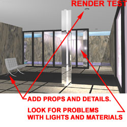 In this final phase of work, you will probably
want to add props and details that will help to make the
final renderings look better. I like to think of this as "dressing the
scene". Running full Rendering tests is obviously necessary to catch
problems with Lights, Materials and objects.
Keep in mind that you can use the
In this final phase of work, you will probably
want to add props and details that will help to make the
final renderings look better. I like to think of this as "dressing the
scene". Running full Rendering tests is obviously necessary to catch
problems with Lights, Materials and objects.
Keep in mind that you can use the