Autodesk® Architectural Desktop™
1.0
In Use...
This page is a continuation of our initial review (First Impressions...) but based on actual use on real
projects.
Thus far we have made several attempts at implementing this
product whole hartedly only to discover too many limitations for successful conversion.
There are two primary reasons for our problems with ADT: one has to do with an
obvious time consuming matter related to the learning curve (trying to figure out how to
make this setting and that setting) but the second has to do with the scope, size and
unusual nature of some of our current projects.
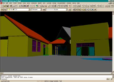
| This illustration
comes from some experiments on a building already drawn in 2D format. Architectural
Desktop is surprising fast as a quick modeling tool. With the
"intelligent" walls, doors windows and roofs, tracing over existing 2D lines
while utilizing auto-snaps is actually quite fun. The limited library of door and
window styles does prove to make for extra work when mullion profiles and door glazing
openings have to be custom drawn. Stairs prove to be
perplexing when attempting to create simple stair and landing conditions and it appears that straight stair landings are not possible at this time
- **This last statement was erroneous and corrected by a reader. Straight
landings are possible, see Building
Stairs in the tips+tricks directory.
Creating the internal winding stairs on this project proved
to be impossible due to the fact that the rails were not similar in angle as the wound
their way around the elevator shaft. This is another serious limitation that has to
be remedied before this particular routine can stand up against the competing stair
routines (see Allplan's stair routine, for example). |
 |
|
|
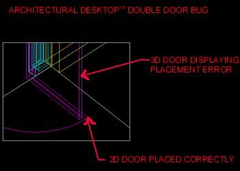
| One of the most
surprising observations was the discovery of such an obvious bug as that of the double
swing door routine. Illustrated to the right is an example of how ADT 1.0 displays
one side of a double swing door in isometric and perspective views; the 3D door actually
floats out and away from it's 2D counterpart. When rendered, light peers right
through the door jamb. |
 |
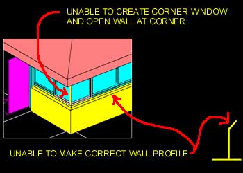
| This illustration
shows other serious problems that occurred while attempting to utilize ADT 1.0. The
elevations of this commercial space needed to clearly indicate that the exterior concrete
wall tapered at the window sills. The wall routine cannot provide this type of
unique adjustment nor can it use a profile shape as a cross-section of the wall. The corner condition was another serious problem that ultimately
forced the project back to a basic 2D format. We could not find any way to bend a
window around a corner and thus made one out of solids (shown). To place this custom
solid window into the wall, we expected to simply use two Openings to blow out the corner
in the wall. Unfortunately, the Opening routine would not allow for a completely
clean corner (see yellow vertical strip in illustration). Of course other solutions
could have been employed, but at some point the work-around effort outweigh the return. |
 |
|
|
| Stair
Limitations: Though you can mix ADT routines
with traditional AutoCAD objects, even surfaces and solids, I was not interested in
producing a non-homogenous product for any of my clients; one mixing surfaces, solids and
ADT object. In one particular test case, I attempted to produce a staircase in a
Victorian building that I could easily model using Solid modeling (see illustration
below). With ADT, however, I found that there was no way to create this particular
type of staircase and while attempting to create it, assuming that I simply did not know
how, I found numerous other limitations. This routine is impressive as it stands,
but the limitations are simply too great for many types of architecture. |
 |
|
|
Decks, Stairs, Columns and Railing Limitations:
Here is one of those routines that I simply didn't
understand fully when I first started using it to solve a real architectural problem.
I had a mezzanine floor inside of an industrial building that was supported by
columns that also served as posts for my railing. Since I saw no options in the
dialogue box for railings that suggested how low I wanted the posts to go, I missed the
obvious. It was really a matter of how high I wanted everything else. Though I
solved the problem, I did find other limitations with the railing routine that relates to
controlling the extensions for guardrails and handrails, but I will hold off on this
matter until the next ARCHIdigm publication. Below is what I posted on the Autodesk
News Group - I figured out the column matter on my own but never got any solid answers for
the creation of pier blocks.
 |
| Deck posts should have an option to carry
through to a floor plane so you don't have disjointed structure (as shown by red deck
columns and green deck columns). - I finally figured this one out and its actually rather
easy. If anyone's interested, I have a rough draft write up on what I learned -> ADT Railings I attempted to create a common pier block (shown in white) only to
rely on basic solid modeling techniques - extrusion with a taper angle.
Also, I have found no way to make my structural columns (in
green) meet the roof plane correctly; i.e., they are square at the top when they should
taper with the slope ...ditto for sloped floors.
ALLplan apparently has the ability to allow for the
establishment of reference planes...these planes thus serve as reference points for other
objects such as walls, columns and roofs. My walls, for example should automatically
detect a base (floor) and a top (ceiling) so that when roof slopes are adjusted walls
follow. |
Wall Limitations:
I find the wall routines impressive - period!
However, I don't find working with them in a 3D environment satisfactory. In
attempting to work with roofs and walls simultaneously, I found that I wished my walls
were connected to my roofs (they aren't and cannot be). Walls have to be assigned
slope in order to match the pitch of a roof and that slope is assigned by specifying
vertex heights; not angles or rise/run. Each time I change my walls or roofs to a
more appropriate value, I have to change the corresponding object by working with dialogue
boxes in a manual fashion. What has really become an irritation, is the inability to
specify points-in-space for these dialogue boxes; with the wall vertex routine, for
example, on a gable end wall, I have to find the vertical height between the floor or
plate and the the gable and then go into the wall dialogue box and input that height for
the affected vertex. Below is what I posted on the Autodesk News Group - I got no
comments.
 |
| I was rather surprised to find that I had to specify the
height of the gable. First, this is one of the reasons I use a CAD system and
secondly, the natural input would not be the height but the slope of the wall at the top
plate ( like 6" / 12" ). Further more, as
mentioned above with respect to Columns, ideally I would just associate the wall with the
roof and not have to do any of this work nor be concerned about the wall or roof if I
change either of them.
If I must specify the height of the gable, I would at least
like to be able to PICK, with my cursor, the distance from the wall to a perpendicular on
the roof. The dialogue box requires that you already know the height and thus forces you
to calculate it or ESC out to take the distance, cut it and then paste that distance value
into this dialogue box. |
Column Limitations:
Columns are quite easy to make in ADT, but then they are
simple objects too. My gripe with columns is that when I attempted to show them
schematically up against a roof plane, I had no way to slope their tops. In fact,
for sloped floors, the same problem exists. Below is what I posted on the Autodesk
News Group - I got no answers.
 |
| In this illustration, I have run my wall up into the roof
sandwich (rafters, etc.) which is acceptable (two top plates would be nice but ...).
In my inserted sketch, I show two possible
scenarios for how a vertical element meets a roof. In some cases, usually schematic
(early development) simply showing a wall or column meeting the roof sandwich would be
nice. In the ADT image (left) the blue column is what I would like to taper so that
it simply flushes up against the roof. Running the column up into the roof sandwich
is not really an option here because it would poke through to the outside of the roof. |