| 1Greetings |
.1-1
INSTALLATION GUIDE |
Introduction
Thank you for purchasing an eParts product from ARCHIdigm.
eParts are comprised of collections of specific Object Types or Categories
such as Refrigerators, Furniture and Street Lights. Many of these
Objects come from our eKit products that offer a whole suite of tools for
specific tasks such as creating kitchen or bathroom designs.
Most eParts have been created as Multi-View
Blocks (MvBlocks) consisting of Model, Plan and Mask components.
Elevation Views are derived from the Model. Masks are for Plan use
only and have been created by using a custom AecPolygon Style with a masking
effect that can be turned on or off at any time. Some MvBlocks have a
higher level of detail under the High Detail than the Low Detail.
Some eParts, like Street Lights, have also
been configured to repeat at intervals that you can control by working with
the custom Curtain Wall Styles. The
Window Styles in this product have been created from Window Styles,
Door/Window Styles (DWA's), and a mixture of both. Window Styles have
been categorized as "Wood", "Stucco" or "Masonry" to provide options for
trim but actually offer the exact same glazing configurations. Window
Styles use customized Structural Members for trim while DWA's use custom
Profiles. |
 |
| 2Installing
eParts |
2-1
INSTALLATION GUIDE |
Downloading and Installing the Files
| Tool |
Download Executable File |

ws10.0_setup.exe |
Right-click over link to the left and use
the "Save Target As..." menu option. Save to your desktop or other
location. Run the executable installation file. Launch
AutoCAD Architecture and Add your new Content Catalog. |
| Keyboard |
Windows
Key + E |
 STEP
1: STEP
1:
After
you have downloaded the "ws10.0_setup.exe" file to
your Desktop or other location, double pick on it, input your password and launch the setup
wizard. Go to Step 2.
Note:
This kit was designed to be installed under the
"C:\Program Files" folder and will not work properly if installed
under other folders (see
Customizing Installation Paths for other options). After installation, you should find that you have
a New folder called "ARCHIdigm" and within this folder is the
"Window Styles 2010 eParts" folder containing all of the Style and
Mvblock files that you will be able to access with your Content Browser.
There is also an "Images" folder that contains all of the Tool
Icons.
Note: The Password is located in
your confirmation e-mail sent out after purchase. If you did not
receive this e-mail, it may have been blocked by a spam filter.
Contact info@archidigm.com to get a
copy.
|
 |
| Provide
Installation Password The password
for your product is located in your purchase confirmation e-mail under the
heading, "keycode". Use this password to complete the installation. |
 |
Add Catalog
| Menu |
Window> Content
Browser |
 |
 |
| Keyboard |
ContentBrowser or Ctrl + 4 |
STEP 2:
When you have completed the "STEP 1" as outlined
above, use the Content Brower in AutoCAD Architecture to "Add an
existing catalog or web site". Use the Browse button on the Add
Catalog dialog box to access the "C:\Program Files\ARCHIdigm\Window
Styles 2010 eParts" folder and look for the "Window Styles
10.0 eParts - by ARCHIdigm.atc" file as illustrated to the right.
Once you have Opened the catalog file, you
should find that you have a new Catalog Library with a Graphic Image that
you can Select to access all of the Tools and Tool Palettes discussed below.
|
 |
| Add Tool
Palette, Category and Tools
STEP 3:
Inside the Window Styles 10.0 eParts Catalog
Library you should find a couple of Categories and several Palettes;
within the Categories are more Palettes. You can drag an entire
Palette to your current Tool Palette or you can drag individual Tools to
your own custom Tool Palette to create a unique collection. Tip:
You can use the Ctrl+A keystroke technique to highlight all tool icons under
a Catalog Category or you can Select off in a corner and use the Selection
Window to highlight a group. The Shift and Ctrl keys work to assist in
Selecting items just as they do in Explorer. |
 |
| 3Using
Window Styles eParts |
3-1
INSTALLATION GUIDE |
| Adding
Window Styles
There are two Window Types in this
package: Window Objects
and Door/Window Assembly Objects.
Adding both Window Types is just like adding native ACA Objects.
The Window Objects are based on standard ACA Styles but with a variety of
modifications like sills and trim. Included with this package are
Window Styles that come straight from the stock ACA library and should behave
just like stock content (trim and hardware has been added). The Door/Window Assembly (DWA) Objects were designed to provide solutions for
more complicated glazing requirements such as those in which multiple
windows reside; i.e., double hung windows on either side of a picture.
In order to
maximize the usefulness of this product, we factored in a variety of user
concerns and preferences. For example, some users simply hate to work
with DWA's so Iwe built a custom set of DWA's that have been embedded in
regular Window Styles. This provides a way to have a composition of
windows within a single Style. We have also created a matching set of
true DWA's for those who don't mind working with these Object Styles.
In other
cases, we were simply limited by the forces that control AutoCAD Architecture.
For example, we could not create automatic trim for Window Styles that are
non-rectangular so we had to create Blocks that will need to be adjusted and
Anchored manually.
Window
Styles have been categorized as Rectangular and Non-Rectangular.
Non-Rectangular Window Styles typically need some form of manual trim work.
|
 |
|
Window Objects |
|
|
Adding Standard Rectangular Window Objects
In the Standard
Category of Rectangular Window Styles, you will find three groups or
Palettes divided into "Wood", "Stucco" and "Masonry". All of these
Window Styles have been customized in a similar fashion. In fact, the
"Wood" and "Stucco" Window Styles are nearly identical.
Each of
these Window Styles has a complex set of Blocks attached to represent top
center, top corner left, top corner right, side, side right, sill center,
sill corner left and sill corner right. In Plan View, illustrated to
the right, you should only see the Blocks for the inside and outside left
and right sides (or jambs).
The shape of
all trim Blocks is controlled by a corresponding Structural Member Style and
the Member Shape assigned to it - see comments below for more information on
this subject.
The Standard
Rectangular Window Styles use the
"Auto-adjust
to Width of Wall" setting and will thus fit any wall width. You
cannot, however, change their shape because Block attachments will not
conform to non-rectangular shapes.
Note: Single and Double Casement
Windows have an arc-swing Block set to Color 54. |
 |
| Window
Display Components for Plan and Plan High Detail
All of the the
custom Trim Blocks have been added as Display
Representation Style Overrides.
These Blocks have only been added to the Display Representations that we
believe are essential thus leaving the other Display Representations stock.
For Elevation,
Model and
Model High Detail
all trim related Blocks have been added; including many that are turned Off
by default. For Plan
and Plan High Detail
only the left and right side (or jamb) Blocks have been attached for the
inside and outside faces.
Because the
Trim Blocks are actually Structural Members, you can alter the appearance,
such as Color and Linetype, of the trim globally or individually. To
make individual changes, use the Display Properties of the Window Style as
illustrated to the right. To make global changes, use the "MemberStyle"
command and modify the Display Properties of the trim Object (see comments
below for more information). |
 |
| Window
Display Components for Elevation, Model and Model High
Detail
Standard and Complex Rectangular Window Styles
have been configured with numerous trim and sill components to allow for a
variety of trim configurations. You will find these Display Components
under the "Elevation", "Model" and "Model High Detail" Display
Representations.
In the
illustration to the right I show how turning these Display Components On or
Off can have a dramatic effect on how the window looks. Sill and Top
Corners come with duplicate components: one that wraps the corner and one
that runs straight out beyond the adjacent trim. Other components
include, four grille configurations, a default muntin layout and a keystone.
When you
reconfigure your window trim, remember to repeat the On/Off settings for
each of the three Display Representations. |
 |
|
Standard Rectangular Window Objects and Trim Profiles
Under the "Windows
- Manual - Trim" Category there
are Palettes containing trim tools for the "Wood", "Stucco" and "Masonry"
Window Styles. At the bottom of each Palette there is a tool for
importing trim profiles.
In the
illustration to the right I show that I have use the "Import and Modify Wood
Trim Profiles" button to import a set of predefined Member Shapes. The
button has automatically launched the "MemberStyle" window because this is
where you set the imported profile. In step 2, illustrated to the
right, I show that I have opened the "Openings_Window_Stucco_Trim_Side_Inside"
Member Style and gone to the "Design Rules" tab to set a new Profile name
(see drop-down list in step 3).
Profiles
under the "Wood" and "Stucco" Window Styles can be used on either Window
Style and many can be used for the interior trim on the "Masonry" Window
Styles.
Creating
custom profiles is a simple process - see
Creating
Custom Trim Shapes for Door and Window Objects below. |
 |
Modifying
Trim on Window Objects
| Palette |
WINDOWS - MANUAL TRIM - STUCCO |
 |
Import and Modify Trim Profile |
| Keyboard |
After
importing more shapes, use "MemberShape" command |
Window Styles labeled with "Trim" as a suffix
in their Style names, use Structural Member Styles for inside and outside
Trim. The trim is actually comprised of a series of Blocks of Columns
attached to the outside edges of the Window Frames. By using this
technique, you can easily change the shape of the Trim by using the "MemberStyle"
command to access the dialog box illustrated to the right.
On the "WINDOWS - MANUAL TRIM - WOOD",
"WINDOWS - MANUAL TRIM - STUCCO", or "WINDOWS - MANUAL TRIM - MASONRY" Palettes, you will find a button labeled "Import
and Modify Trim Profile" and when you
pick on this button, it will insert a collection of predefined Member Shapes
(see discussion below). Once the custom Member Shapes have been
imported into your drawing, you can use the "MemberStyle" command to access
the Trim Styles and change the shapes under
the "Design Rules" tab, "Name" drop-down list, to other trim shape names.
Note:
Windows with Trim have been divided into trim groups. Any profile
change you make to trim within one trim group, such as "stucco", will affect
all window styles belonging to that trim group. Should you need to have a unique trim for any single
Window Object, you can use a Window from another trim group, such as "wood",
and simply apply stucco profiles to it. You can also Import that
Window Style into a Blank ACA Template drawing, Rename the Window Style, Rename the Structural
Member Styles (to something like "Openings_Window_Stucco_2_Trim_Side_Outside") and
then use the "Rename" command to rename each of the trim Blocks. When
done, import the modified Window Object into the working file. |
 |
|
Understanding Trim Corners (wrapping and straight)
Window Styles
in this product have a total of eight top corner Blocks: for each of the
four corners there is one that runs "straight" and one that wraps at 90
degrees. The wrapping top corner Blocks have been set as the default
corners. These Blocks are comprised of two separate Structural Members
that meet at 45 degrees and use the "Side" Member Profile.
The corner
trim was designed to accept Profiles for things like flutes. However,
should you want to create a unique corner trim solution, you can replace or
substitute your own design for our default one. Each corner has a
unique Block name based on the window type (wood = w, stucco = s and masonry
= m) and the position (in = inside, out = outside, default is left but right
= right). For example, "Openings_window_trim_
s_top_corner_out", is a top
outside left corner Block for the
 Stucco
Window Style. Stucco
Window Style.
Illustrated
to the left is a top corner outside straight Block with a return component
similar to that found on the Sill corners. To increase or decrease the
length of this component, see "Modifying
the Straight Corner Blocks" below. These Blocks are set to use the
"Top" Member Profile.
|
 |
|
Creating
Custom Trim Shapes for Door and Window Objects
In the illustration to the right I show three
example Trim Profile Shapes that were created with Polylines. To
create your own shape, simply draw a closed Polyline form, to scale, and use
the "MemberShape" command to activate the dialog illustrated to the right.
The Structural Member Shape Definitions
dialog shows three Display Representations under the Shape Geometry
category. Use the "Specify Rings for ..." button to
Select your custom Polyline shape for each Display Representation. For advanced users,
you can actually specify different Polyline shapes for different Display
Representations.
The insertion point for your custom Polyline
shape is always the upper right corner, as illustrated, and the outside face
is always along the x-axis pointing towards the negative "Y" direction. |
 |
| Adding
Windows with Masonry Trim
The Window
Styles that were designed for masonry trim, typically brick, are the most
difficult to work with because you can't rely on the "Auto-Adjust to Width
of Wall" feature.
In the
illustration to the right I show that I have added a window with masonry
trim to an out of the box brick wall from AutoCAD Architecture's library.
The first thing you will need to do is set the Window
Style's Depth value to match the
depth of the Wall from the brick to the inside face (see illustration).
The frame will act as the casing.
The next
step is to use the Anchor dialog box,
accessed from the Window Properties Palette.
On the Anchor dialog, set the Position Within (Y)
values as "From: Right
edge of wall width", "Distance:
0" and "To: Front
of object". This adjustment
should push the inside trim to the inside face of the finished material on
the wall as illustrated to the right. If this doesn't add up
correctly, you may need to adjust the Depth value on the Window Style
Properties dialog or use a "Distance" value on the Anchor dialog.
|
 |
|
Subtracting a Window with Masonry Trim from a Wall (optional)
In the
illustration to the right I show a scenario in which a the bricks, in plan,
wrap the exterior window opening. In most cases, you would use an
Opening Endcap Style
for placed on the Wall Object or Style. However, as an alternative and
as general information that you may want to employ whenever it seems
appropriate, you can use a Wall Interference Condition
and Add the
Window Object as
a Subtractive
Object.
|
 |
|
Exterior Trim Blocks on Masonry Window Styles
The trim blocks
attached to the exterior side of the masonry style windows are very similar
to the blocks used on the wood and stucco window styles. However, in
order to provide solutions more appropriate for masonry conditions, the
Blocks were set to the outside face of the surrounding Frame Component.
In order to allow for Sill Profiles that have a slight slope, the Blocks
were set to .25 inched above the outside face of the bottom Frame Component.
All of the
"Straight" Corner Blocks have been adjusted to a width of 3 1/2" to match
the width of a common brick. |
 |
|
Modifying
the Straight Corner Blocks
You can modify
any and all of the trim blocks but the only ones you are likely to modify
regularly are the ones designer for straight corners. There are
duplicate corner blocks: the non-straight ones simply wrap to produce a 90
degree corner while the straight ones run straight beyond the side trim and
wrap inward towards the wall.
In the illustration to the right I show that
I have inserted the four outside straight corner trim blocks for the stucco
window style. These have the following names: "Openings_window_trim_s_top_corner_out_straight"
"Openings_window_trim_s_top_corner_out_straight_right" "Openings_window_trim_s_sill_corner_out_straight"
"Openings_window_trim_s_sill_corner_out_straight_right"
In the lower
right illustration I show that I have use Refedit
to go inside one of the sill blocks where I have the structural member grips
that allow me to Stretch the trim to make it longer or shorter.
|
 |
| Composite
Window Panel Breakdown
The default Window Styles are limited to single
window configurations and thus do not provide options for more complex
arrangements such as side-by-side and/or above-below layouts. For
these types of arrangements, ACA users are supposed to use Door/Window
Assembly Styles and we have included such styles in this product.
However, for users who would prefer to work with standard Window Styles, we
created a hybrid that places a block of a Door/Window Assembly inside a
standard window. This approach is identical to how we created highly
customized door panels in our Doors eParts Product.
1) Custom
Window Styles were created for use in Door/Window Assemblies. These
have been labeled with the prefix "DWA" and have no Frames.
2) Custom
Door/Window Assembly Styles were created to house the custom Window Styles
in common arrangements such as the one illustrated to the right.
3) The
Custom DWA's were turned into Blocks so they could be Attached to Custom
Window Styles.
4) Custom
Window Styles were created with Display Property Overrides replacing the
default Glass Display Component with the Custom Block. The Sash
dimensions for these Custom Window Styles has been set to zero.
This means
that if you want to modify the Window Panel, you can insert the Block
for that Panel and "Refedit" (Edit the Block in Place) it or go
straight to the Door/Window Style dialog and work through it. To
change the Materials, for example, it would much better to go to the
Door/Window Style.
In the
illustration to the right I show how the names of these components have been
structured to help find matches. |

Note:
Because the DWA's are Blocks inside Windows, they will distort as you change
the Window Size. If you Modify the DWA to match the desired size, the
distortion will be eliminated but only for one window size. If this is
a problem, look into using our Door/Window Assembly Styles instead. |
| Composite
Window Panel
Display Properties
In the illustration to the right I show how
the default Glass Display Component is replaced with the DWA Style Block.
Under the Display Properties,
the Glass Display Component
has been turned Off
but in its place, is a custom
Block added under the "Other"
tab.
Note:
Notice that the trim components are also added as Blocks here.
You can use the Remove button to remove the trim or you can use the
Layer/Color/Linetype tab to turn the trim off for one or more Display
Representations. |
 |
"Windows -
Standard - Non-Rectangular" and Manual Trim
| Palette |
WINDOWS - NON-RECTANGULAR - STUCCO |
 |
Picture - Arched - Stucco - Trim |
| Palette |
WINDOWS - MANUAL TRIM - STUCCO |
 |
Insert
Exterior Arch Trim |
| Keyboard |
|
It is
unfortunate that the way Blocks can be set to match a Window's Width and
Height does not include a Window's shape. In other words, it was only
possible to provide automated trim on rectangular Window shapes so for all
non-rectangular shapes, we created Blocks for manual placement and
adjustment. In addition, we created a set of Window Styles for
non-rectangular shapes and included Sill Blocks wherever possible.
In the
illustration to the right I show that I have gone to the "Windows -
Non-rectangular - Stucco" Palette from the "Windows - Standard -
Non-Rectangular" Category and added the "Picture - Arched - Stucco - Trim"
Window Style. In Plan View this Window Style will appear as complete
as the rectangular version, however, in a Model View, you will find that the
side and top trim components are missing.
Under the "Windows
- Manual - Trim" Category I went
to the "Windows - Manual Trim - Stucco"
Palette and inserted an exterior trim Block to match the Window shape.
For most of these predefined trim shape Blocks, the insertion point is the
inside bottom edge of the left jamb. Once inserted, the trim can be
modified using the Structural Member Grips
|
 |
| "Windows -
Standard - Non-Rectangular" and Manual Trim for the Inside
Once you have
the Exterior Trim placed and sized to fit your Window, use the "Mirror"
command to make a copy of it for the inside trim. I prefer to mirror
in Plan View through the Midpoint of the Jamb.
After you
have the Mirrored trim, Select it and then go to the Style drop-down list on
the Properties Palette to set an "Inside" trim style.
Note:
Because Manual Trim Blocks are inserted as Blocks, they will not Key to a
Layer so you will need to set them to whatever Layer you feel is
appropriate. |
 |
Manual
Trim and Anchoring
| Palette |
WINDOWS - MANUAL TRIM - STUCCO |
 |
Anchor
Trim to Door or Window Object |
| Keyboard |
Anchor, Object |
At the
bottom of each of the Manual Trim Palettes is a Tool for Anchoring Objects,
like the trim, to Windows. This will keep the trim connected to the
Window Object if you move it. However, it does not change the trim
size or shape so if you make those types of changes to your non-rectangular
window, you will have to modify the trim to match.
You can
Anchor Shutters in the same way.
Note:
Do not attempt to
Anchor trim objects that are comprised of two separate parts, such as the
round,
ellipse,
hexagon and
octagon. For some reason
AutoCAD Architecture's Structural Members separate and sometimes even roll
when combined and anchored like this. Any single Structural Member
Anchors without problems, but when two touch and are then Anchored, trouble
arises.
|
 |
Manual
Trim for Masonry Window Styles
| Palette |
WINDOWS - MANUAL TRIM - MASONRY |
 |
Insert Exterior Peak Pentagon Trim |
| Keyboard |
|
By far,
creating solutions for masonry trim was the most difficult challenge in this
whole product and admittedly the least complete. Bricks for example,
are not extruded forms that follow a shape in one contiguous form.
Hatch Patterns don't exist that can radiate as a brick through an arch.
Render Materials have to be customized to individual forms.
For
Non-Rectangular Masonry Window Styles that don't have curves, we created a
set of Blocks using Member Styles where Render Materials and Hatch Patterns
follow the angle.
 For
Non-Rectangular Masonry Window Styles that do have curves, we created
customized Member Styles that attempt to work like real bricks. By
having a Block repeat along a Member Object, each brick and mortar joint is
represented realistically without Hatch Patterns. This solution,
however, can prove problematic in some situations and may not work at all;
corners where arched tops meet sides, for example. For
Non-Rectangular Masonry Window Styles that do have curves, we created
customized Member Styles that attempt to work like real bricks. By
having a Block repeat along a Member Object, each brick and mortar joint is
represented realistically without Hatch Patterns. This solution,
however, can prove problematic in some situations and may not work at all;
corners where arched tops meet sides, for example.
Illustrated
to the left I show what typically happens when you attempt to modify the
arch on the Arched Brick Trim with Sides Styles. In fact, system
hang-ups can also occur so be sure to save before trying to work with these
styles. Under the
"WINDOWS - EXPERIMENTAL TRIM"
Palette there are a few examples of Railing Styles that have been designed
for this scenario and though they offer somewhat acceptable solutions, they
cannot be displayed as Plan View Objects. |
 |
Manual Trim
for any Window
| Palette |
WINDOWS - MANUAL TRIM - WOOD |
 |
Insert Exterior Sill with Returns |
| Keyboard |
|
In order to
provide a complete Trim solution, we included a set of Interior and Exterior
Trim Blocks that can be used for any Window (like the stock content).
These are based on the Blocks embedded in the Rectangular Windows but may
have unique features such as that illustrated to the right where the Sill
has five Components.
|
 |
| Windows -
Experimental Trim
Under the "Windows -
Manual Trim" Category, we included
a Palette named "WINDOWS - EXPERIMENTAL TRIM"
for the adventurous ACA user who may want to know about other possible
options for creating trim in ACA. Be aware, however, that these
"solutions" have been placed into this unique category because there may be
issues with things like Cut Planes and/or Display Representations.
Illustrated
to the right I show one of my favorite trim solutions from the experimental
category: the round shape. The round trim shape is one of the worst to
deal with in ACA because you cannot attach Blocks that will automatically
adjust correctly and you cannot use a single Structural Member because they
can't be closed shapes. DWA's offer the option to set a Shape so that
made it a great candidate for experimental trim. However, when a DWA
is perfectly round, it has no Plan Display Components for the Frame because
there is no vertical Frame; only a Top and a Bottom. Therefore, in
this illustration to the right I show that I had to set the Height for this
example round DWA slighly greater than the Length.
|
 |
|
Door/Window Assembly Objects |
|
| Working
with Door/Window Assembly Objects
When you add one of our customized DWA Objects, such as those for Entry
Systems, you should find that they
behave much like regular ACA DWA Objects. However, there is one one
major difference and that has to do with our efforts to provide a solution
for trim. DWA's use a Frame component for Jambs, Heads and Sills and
since these accept custom Profile shapes, we created a default "C"
shape to produce a trim-like effect. Unlike the trim we used for our
Door Objects, this profile solution is somewhat static and does not
automatically adjust to varying Wall Thicknesses. Once you develop the
skills to modify the Profiles and a few DWA Style settings, you should find
that the limitations are not that dreadful.
Note:
The DWA's that are meant to hold Arched Top Window Styles, may insert with the
Window Styles
set to a Rise of 0" which will cause the error illustrated to the left.
To fix, simply Select the Door(s) and change the Rise value to something
appropriate for the DWA housing the Door(s). This is a problem with
ACA so I experimented with another solution and if you are curious, look
under the Barn Window Styles in the "Experimental" section. I used a CWU in
place of a Door but that has its own problems - good for fast design studies
though. Note: The "FacetDev"
setting can be used to improve the appearance of curved surfaces. Set
to a lower number to improve things like arched top Window Styles. The default
value is 1/2. I often use 1/10 - 1/100 depending on the size of the
file and the detail needed. |
 |
|
Door/Window Assembly Panel Breakdown
If you have
reviewed the breakdown of the Composite Window Styles, you should already
have a fundamental understanding of how Door/Window Assemblies are used for
multiple glazing combinations.
DWA's would
be the optimum solution for complex window assemblies were it not for the
fact that they don't offer the same functionality and features as regular
Window Styles. For example, DWA's don't have an option for
Auto-Adjusting to Wall Widths.
To create a
trim solution for DWA's, we created Profiles that modify the Frame
Components of our customized Styles. The Frames have been divided into
"Top", "Jamb" and "Sill" allowing unique Profiles to be assigned to each of
these components.
The internal
structure of our customized DWA's is fairly simple, using Division and
Mullions to create Cells in which Windows and/or Curtain Wall Units have
been assigned. All Window Style Names designed for use in DWA's use
the prefix "DWA" and are devoid of Frames. Curtain Wall Units are used
where we anticipated changes in the Shape. Curtain Wall Units
automatically adjust to Shape changes in DWA's.
DWA Styles
available in this package should be seen as templates for your own
creations. It is fairly easy to take an existing DWA configuration and
change Window Styles (for more, see below). |
 |
| Modifying
Door/Window Assembly Shape and Infill Assignments
Modifying the
Shape and Infill Assignments of DWA's is a very simple task. If you wish to
use a Window Style other than those already in the DWA you want to modify,
you may want to add another DWA that has the Window Style(s) that you need.
Though you can assign any Window Style, the ones we created for "DWA" should
provide better results.
Illustrated
to the right I show an example of how I have used the "DoorWinAssemblyStyleEdit"
command to access the Style Properties for my "Openings - Window - DHPDH - U
- PPP - Trim" Window. Under the Shape
tab I show that I have selected the "Arch"
Shape which will allow me to alter the Rise of the Arch on the Properties
Palette.
Under the
Design Rules tab
I show that I have highlighted the "Infills"
category under the "Element
Definition"
section to reveal that this particular DWA has three Window Assignments: End
Windows, Middle Window and Top Window. This example DWA has Double
Hung Windows on each end with a Picture in the middle. By Selecting
the Middle Window and setting it to "DWA - Double Hung", I have changed this
DWA to have three Double Hung Windows.
Note:
Another way to access Window Styles is to type "Window
Styles" and
then Open "C:\Program Files\ARCHIdigm\Window Styles 2010 eParts\Window
Styles
eParts - (Imperial).dwg". All of the Residential Window
Styles
are located in this file and those with the prefix "DWA" are for use in DWA
Entry System Styles. This action can be repeated for CWU's by typing "CwUnitStyle". |
 |
| Creating
Custom Trim Shapes for Door/Window Assembly Objects
The Window DWA's
in this product use
Profile Definition Styles to produce a trim-like appearance and
the one major drawback to this solution is that the Profiles don't
automatically adjust to varying Wall Widths. In the illustration to
the right I show an example of how the default
Profile Definition Style,
named "Openings_DWA_Trim_
6_inch_Wall_1x5.5_out_curvy_in", isn't deep enough to match the Wall Object
it has been placed in. Because the trim has been drawn as 1" thick on
each side of the Profile, it does protrude out beyond the Wall edges and may
never be noticed as a problem. However, it isn't that difficult to fix
and knowing how to fix it will allow you to create more customized trim
solutions.
The default
Profile can be inserted using the "Profile" command
with the "P" option. You can use the default shape to assist you in
creating a new one or you can simply draw a Closed Polyline shape. Use
the diagram to the right as your guide for drawing the Jamb and Head
Profile. In my example to the right I show how my new Profile, green
color, relates to the original, blue color.
 Once
you have a Profile, use the "Profile" command to create or modify a
Definition Style. Highlight the Definition Style name, right-click
Select "Set From" on the context menu and then Select your closed Polyline
shape. For best results, use the insertion Base Point illustrated to
the right based on a 5 1/2" x 6" rectangle (don't use
the default "Centroid" option). If you use our base point, you
won't have to modify any of the default values for the Frames of the DWA
unless you define a thicker Jamb (requiring a modification to the X-Offset
value). Once
you have a Profile, use the "Profile" command to create or modify a
Definition Style. Highlight the Definition Style name, right-click
Select "Set From" on the context menu and then Select your closed Polyline
shape. For best results, use the insertion Base Point illustrated to
the right based on a 5 1/2" x 6" rectangle (don't use
the default "Centroid" option). If you use our base point, you
won't have to modify any of the default values for the Frames of the DWA
unless you define a thicker Jamb (requiring a modification to the X-Offset
value).
Once you
have a new or modified Profile, Select the DWA Object that you want to apply
this Profile to and use the Door/Window Assembly Style Properties dialog to
access the Frames category. Illustrated to the right I show
that I have set the Jambs Frame Component to a new Profile named "Openings_DWA_Trim_
6_inch_Wall_1x5.5_out_curvy_in".
I have also set the Head Frame Component to the same new Profile but will
have to create a new Profile for the Sill Frame Component (see below).
Note:
In the Doors 9.0 eParts product I recommended using the "Auto-Adjust Profile" Depth
setting but have decided that not only is it more accurate to just create a
new Profile but easier if you keep a small library of common Wall Widths
that you use in your office.
Note:
You can also edit a Profile right in place using the "GridAssemblyProfileEdit"
command but this creates a copy of the original and can get a bit confusing
later on. It's a great option when you are in a hurry. |
 |
| Creating
Custom Sill Shapes for Door/Window Assembly Objects
Illustrated to
the right I show a scenario similar to the one outlined above but for the
Sill Frame Component. The only difference between the creation of
custom Profiles for the Sills and the Jambs is that the Insertion Base Point
for the Sills is based on a 5" x 6" rectangle. |
 |
Adding a
Keystone to a Door/Window Assembly Object
| Palette |
WINDOWS - ASSEMBLIES (DWA) |
 |
Insert Keystone for DWA |
| Keyboard |
|
Under the "WINDOWS
- ASSEMBLIES (DWA)" Palette you
will find a Keystone Block designed specifically for use with Door/Window
Assembly Styles. This Block is set to use the "Openings_Window_Trim_Keystone"
Member Profile and has been rotated to align properly with the Head
Component of our DWA Styles.
The Block
has not been attached by default, as with the Window Styles, because
attaching Blocks to DWA Styles can cause a Material Assignment bug to occur
(see yellow component color, right). This bug does not appear to occur
in ACA 2010.
After
inserting the keystone Block, you can delete it. To attach it to a DWA
Style, go to the Model Display Representation
and use the Other
tab to Add...
a Custom Display Component. On the Custom Display
Component dialog, set the
Component Type to "Frame".
Use the "Select Element...
button to Select
the "Head"
Component Name. Check
the "Draw Custom Graphics box.
Use the Select Block...
button to select the "Openings_dwa_trim_keystone_default"
Block. Set the Insertion Points such that X=Left,
Y=Front and Z=Center.
These unusual points are the result of the fact that the top or head
component has a horizontal normal; i.e., the Z-axis represents the Length.
|
 |
|
Other Items in this Product |
|
| Windows -
Spoke Round and Oval Window Styles
in ACA don't offer the common spoke grille so we did our best to remedy that
missing item. Illustrated to the right I show a breakdown of our
default spoke grille. The spoke is actually based on a Window Style,
named "Openings_Window_Spoke_48", but the Block uses a concoction of
ACA tricks to produce a true spoke by using a mirrored version of the top
spoke. Extra unwanted muntins were removed with Mass Elements by
wrapping each half in individual Mass Groups.
Essentially all you need to understand is
that if you want to modify the spoke dimensions or layout, just use the "WindowStyle"
command and modify the Spoke Window Style. However, if you want to
modify the Material assignment, you will need to Insert the spoke Block, "Openings_window_grille_spoke_48",
for example, and use Refedit to access the two Mass Groups within it.
Select one Mass Group, right-click and use the "Edit Object Display..."
context menu option to set a new Material. Then, repeat this work for
the other Mass Group and close out of the Refedit mode. |
 |
| Windows -
Shutters Under the "WINDOWS -
SHUTTERS" Palette there are numerous Window Styles configured to display
six different Shutter Types: 1 Panel Louver, 2 Panel Louver, 1 Panel Solid,
2 Panel Solid, Board and Batten and Bermuda. There is a set for each
of the three Rectangular Window Trim Types and a set for Half Round
Non-Rectangular Windows.
This Palette also contains single and double
shutter styles for manual placement. All Shutter Styles are based on
Door/Window Assemblies and if manually placed, should not be Anchored
to Walls.
In the illustration to the right I show the
Half Round Stucco Window Style (stucco sill) and the 2 Panel Louver Quarter
Round Shutter (RL2PQR). Unfortunately, if you need to create shutters
for Arched Windows, you will have to use a Profile.
In Plan View, Shutters are represented by a
Block of a custom AecPolygon with the Style Name, "Openings - Window -
Shutters - Plan - Mask". This Style has been set to Mask Objects
by default but it was not possible to mask the Sill linework as illustrated
upper right. This Style can be modified to show Hatch Patterns. |
 |
| Material
Assignments The Standard
Rectangular Window Styles follow the standard rules that apply to the
default Window Styles in ACA. However, most of our Window Styles
required Display Property Overrides and will thus require modification on a
Style based level as opposed to a global based level. In addition, we
added Trim, Grilles and Keystones which are all based on other Object Styles
and cannot be modified from within the Window Styles dialog. Trim, for
example, has been created from Structural Members and thus requires that you
use the "MemberStyle" command in order to change Material Assignments.
Note:
Due to problems with the "Merge Common Material" setting in ACA, we have
created two default Materials for white trim named, "Openings.Trim.Paint.Semigloss.White"
and "Openings.Trim.Paint.Semigloss.White.Merge". The
Merged version is likely to create poor results when used on Door/Window
Assembly Styles but appears to work properly on Window Styles. See "Merge Common Material Bug in AutoCAD Architecture"
for more information.
|
Material Assignments for
Window Objects
Trim - use "MemberStyle"
Louvers - use "CwUnitStyle"
Shutters - use "DoorWinAssemblyStyle"
Short Grilles - use "CwUnitStyle"
Bricks - use "MassElementStyle"
Keystone - use "MemberStyle"
Material Assignments for
Door/Window Assembly Objects
Trim - use "DoorWinAssemblyStyle"
Mullions - use "DoorWinAssemblyStyle" |
| Improving
Material and Hatch Pattern Spacing on Trim Objects
The Trim Blocks attached to the Standard
Rectangular Window Styles are Structural Member Objects set to automatically
adjust to the Length and Height of the Window Objects. Because of this
auto-adjustment, Material Mapping and Hatch Patterns may distort.
In the illustration to the right I show that
I have inserted the sill Block for the Masonry Window Style and am in the
process of Stretching the sill while in Refedit mode. If I match the
length of the sill to the length of the Window, the Material will mapping
will improve. However, if you have numerous Windows of different
Lengths using the same Sill Block, this solution may not prove particularly
useful.
|
 |
Bay Window
Examples
| Palette |
WINDOWS - EXTRAS |
 |
135d Bay Window |
| Ref.Files |
windows -
examples - bay 90d.dwg
windows - examples - bay 135d.dwg
windows - examples - bay 150d.dwg |
Under the "Windows - Extra Items"
Category is a Palette named "WINDOWS - EXTRAS" which has a few
example Bay Windows that can be inserted as Blocks. These Blocks have
been created to provide examples of how trim for bay window can be produced.
For greater clarity you can open the drawing files in which these styles
reside and see all of the components that were modified to provide the
specific solutions provided in these examples. If you save these files
for your own use, you should be able to modify the components for your own
needs.
Illustrated to the right I show the example
file for the 135d Wood Bay Window Style. There are actually two
Styles, one for the Sides and one for the Center. What makes these
Window Styles different from the regular rectangular ones, is that the Trim
Components for the angles that meet are unique; using new Member Profiles
and modified corner Components. In Plan View, all you need is a
Profile that matches your trim needs for a corner and then assign it to the
corresponding Member Style Name; e.g., "Openings_Window_Wood_
Trim_Side_Outside_Bay". The Sill and Top corners are no where as easy
to modify. The key for these corner components is setting the Length
and the Trim Angle. The example files have these Blocks ready for
modification and the work can be done with RefEdit - see "Modifying
the Straight Corner Blocks" above.
Note:
Each Bay Window Style uses the same Component Names for each example angle.
This makes it impossible to use two different bay window angle examples in
the same file. However, you can use one Stucco and one Wood bay window
from different example files. If you need to use more bay angles, you
will need to create one solution in an isolated file and Rename the Window
Style(s), Member Styles and Blocks. For the Blocks and Member Styles
you will only need to Rename those that already have the suffix "Bay". |
 |
Mitered Butt
Glazed Window Example
| Palette |
WINDOWS - EXTRAS |
 |
90d Mitered Butt Glazed Window |
| Ref.Files |
windows -
examples - mitered 90d.dwg |
| Links |
Mitered Corner Glazing in Architectural Desktop - for steps but I
recommend using "WallBody" instead because now you can always edit the
original Mass Element if needed. |
Under the "Windows - Extra Items"
Category is a Palette named "WINDOWS - EXTRAS" which has a single
example of a Mitered Butt Glazed DWA Style that can be inserted as a Block.
Illustrated to the right I show the example
file for the mitered window style. The style uses a modified version
of the "Picture - Trim" Door/Window Assembly Style. This
style uses a Curtain Wall Unit Style as a Window because this allows for
unique control over the glazing component. The DWA Style has the "Right"
Frame (named "Jamb") turned Off so only the Left Jamb
displays. The same is true of the CWA Style that is used as Infill.
On the Properties Palette I show that I have
used the End Miter Angle to set the selected DWA to use 45
degrees. I repeated this step for the CWU. The work needs to be
repeated for the other corner window.
The worst part about creating this solution
has to do with the Wall. The Wall will leave a rectangular column at
the corner and thus you have to find a creative way to remove that mess.
My solution is to Add a Rectangular Mass Element right over
the unwanted Wall matter and then use the "WallBody" command to
Add the Mass Element as a Subtractive component.
This work has to be repeated for the second Wall. "WallBodyEdit"
command can be used to modify the Mass Element.
Note:
The Sill Plan Display Representation doesn't work for mitered corners so it
has been turned Off. You can use the Above or Below Display Components
but they will display lines inside the Wall so I just draw them manually. |
 |
Faux and False
Balconies
| Palette |
WINDOWS - FAUX BALCONIES |
 |
Balcony - False 2 |
| Keyboard |
|
As part of the "Extras" in this product, we
added some Railing Styles for Faux and False Window Balconies. On the
"WINDOWS - FAUX BALCONIES" Palette, there are a group of MvBlocks that
combine the Railing with a Base but you can very easily create these by
using the Railing and Base Object Tools on this Palette.
Slab Styles are the logical choice for bases
but we also created a custom Railing Style that uses a Mass Element Block in
place of the Balusters to create a true 3D grating.
Slab Styles may require a Cut Plane
adjustment to the Style Override if you move the Balcony up the Z-axis.
Note:
You can Anchor a Balcony to a Window Object just as you can Anchor a Trim
Object; i.e., you can use the same Anchor Tool. |
 |
| 2D Projected
Elevation/Section Results with Missing Trim
In the illustration to the right I show an
example of how trim may disappear in 2D Projected Elevations and Sections.
The cause of this is may be due to conflicting or overly complicated trim
components. In some cases, for example, I have experienced this
problem due to inadvertently leaving both the true corner and straight
corner trim components on.
If you experience this problem, the best
solution I have come up with thus far is to simply change the Material for
the problematic trim components. As illustrated, lower right, use the
Structural Member Style dialog to access the trim components and then change
the Material to one that does not use the "merge" option.
|
 |
|
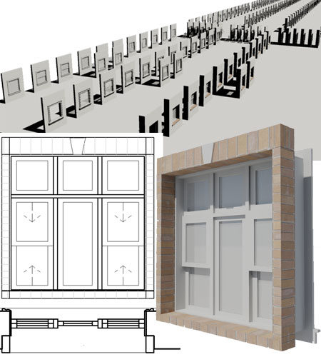
Template Files and Display Configurations
All ePart Objects have been optimized for
work using the AutoCAD Architecture 2007 - 2009 "Aec model
 (imperal
- ctb).dwt" and "Aec model (imperal -
stb).dwt" default template files. (imperal
- ctb).dwt" and "Aec model (imperal -
stb).dwt" default template files.
Illustrated to the right is an example of how
the three primary Display Representations, Low, Medium
and High Detail, affect ePart Objects. Most ePart
Objects include an AecPolygon Style set to Mask background information.
This mask can be turned off if desired.
Low Detail
The Low Detail Display Representation will affect the Plan and Model
Display Representations. In Plan View linework has been simplified to
a little as possible while conveying the basic information of the Object. In Model View this Detail Display Representation will
show Objects in Colors you specify by direct assignment or by Layer; i.e.,
the Objects are set to "ByBlock".
Medium Detail
The Medium Detail Display Representation will affect the Plan and Model
Display Representations. In Plan View you will see either see the same
amount of detail as under Low Detail or High Detail depending on what we
considered the better choice. In
Model View Colors are determined by the Material assignment and do not use
image maps.
High Detail
The High Detail Display Representation will also affect the Plan and
Model Display Representations. In Plan View all linework is displayed..
In Model View Objects will display Materials by their image map assignment
ready for Rendering.
|
 |
| 4Modifying
eParts |
4-1
INSTALLATION GUIDE |
| Multi-View
Block Anatomy
Most ePart Objects involve a complicated set of
regular Blocks that have been assembled into a Multi-View Block. The
complexity varies and may never be something you will have to think about
but if you ever have a need to change one of these Objects, you will need to
understand how they have been assembled.
The most
important thing that you need to understand about MvBlocks is that there is
always a duplicate Block of the 3D Model Representation. By looking
under the Model Display Representation on the Multi-View Block Definition
Properties dialog, you can find the name of this matching 3D Model Block.
By inserting this Block you can use Refedit to make changes to things like
Material Assignments, Height, Width and so forth.
Multi-View
Blocks also provide the option to set different Blocks for Top (Plan) Views
and these may even be different for Low, Medium and High Detail Display
Representations. A feature of our eParts Objects is the use of custom
AecPolygon Styles that act as Masks to hide Objects below. If these
mask blocks produce undesirable results, you can turn off the masking
feature - see comments below. |
 |
|
Masks, AecPolygons and MvBlocks
Most ePart
Objects include a Masking Block as part of their structure. These
Masking Block have been created by making a Block of an AecPolygon Object
set to a custom Style where the "Use Background Mask" feature has been
activated.
By typing "AecPolygonStyle"
on the command line, you should see a list of Styles with the word "mask" as
suffix. By Editing any of these Styles and unchecking the "Use
Background Mask" feature found
under the "Other" tab you can remove the masking behavior - see illustration
right.
Mask Blocks
may produce undesirable results when printing from Model Space due to the
Black Background but this is not a problem when printing from Paper Space
Layouts.
The "DrawOrder"
command can be used to move Mask Blocks up or down in the display stack.
Note:
AecPolygon Styles offer powerful presentation options under the
Display Properties tab and you may want to explore things like
Hatching all of your Objects or even Filling them with a solid
Color. By default, Fills only display under the Presentation Display
Configuration. |
 |
Materials and
Mass Elements
| Command |
MaterialDefine |
| |
MassElementStyle |
Most ePart Objects incorporate Mass Elements
as a means of providing a 3D Model that will accept Material Definition
Assignments. In other cases native Object Styles, such as Structural
Members, Curtain Walls and Railings have been used whenever feasible and
their Material Definition Assignments are managed by the Object Style.
For Mass Elements, however, the Objects have
typically been assigned to one custom Mass Element Style and Material
Assignments set as Object Display Overrides. For Objects such as this,
you can use the Refedit command to access the Edit Object Display... context
menu option to change the Material Definition Override under the "Materials"
tab - see illustration to the right.
Keep in mind that an MvBlocks contains one or
more regular Blocks so in order to access the actual 3D Model information
you need to Insert the 3D Model Block, typically denoted by an "m" suffix.
Once you have inserted the 3D Model Block, you can use the Refedit command
to access the contents inside the Block in a way that will ripple back to
the MvBlock once you save the changes.
If you Open the eParts source file you will
find that most of the 3D Model Blocks have been inserted for you so you can
more easily identify them and even change them in this source file if you
feel the need. Note:
For the majority of Mass Element Objects in the Window Styles package, unique
Mass Element Styles have been created. This will allow for Material
Assignment changes on Objects that may be embedded within other Object
Styles; such as hardware on a Door Style. Check your Mass Element
Style list. |
 |
| Materials - an
alternative approach to changing the Rendering Material
If you are in a hurry and don't have the
patience to change Material Definition Assignments remember that you can
always change the Material Definition Style itself. For example, just
because a Material Definition Style is named "Streets.Glossy.Black.Green"
does not mean that you can't change the actual Rendering Material to a
Glossy Red.
|
 |
|
5Relocating
a Catalog |
|
| Overview about
Moving a Catalog AutoCAD
Architecture's Content Catalog offers a Publish tool that assists users with
the management of Catalog and drawing file paths. This tool works well
with ACA items such as Object Styles and MvBlocks but ignores regular
AutoCAD objects like Blocks. Our eKits and eParts often include tools
set to insert regular AutoCAD Blocks. These tools have to be fixed
manually if you intend to move a catalog to a server or other location. |
|
|
Customizing Installation Paths
Note: Be
sure to create your folder structure for the new location prior to using the
Publish tool. I recommend that you use the same folder name for this
product as was used for the default installation.
Though this product has been configured for installation under the "C:\Program
Files\ARCHIdigm\Window Styles 2010 eParts" path, you can alter this after you have
installed and loaded it in your Content Browser.
From the Content Browser, Select the "Window
Styles
10.0 ePart - by ARCHIdigm" Catalog icon, right-click and Select the "Publish
'Window Styles 10.0 ePart - by ARCHIdigm'" from the context menu - as illustrated right. On the
Publish Tool Catalog - Step 1 of 4 dialog box, you can use the Move or
Copy options to direct this product to a new folder location on your local drive
or on a Network Server. I highly recommend that you create a new
folder location that uses the same primary folder name as the one we
assigned for the original installation; e.g., "X:\my server\my ACA content\Window
Styles 2010 eParts".
On the Publish Tool Catalog - Step 2 of 4
dialog box, use the ellipses (...) button to specify a new location for
the catalog. On the Publish Tool Catalog - Step 3 of 4 dialog
box, use the same location path as the one you previously specified since
that is where all of the "tool dependant files" need to go and check both "reference" related checkboxes.
The final step completes the task and provides a report on any errors.
You should now find a new Tool Catalog.
If you used the Copy option the new Catalog will have "Copy" in the title
but you can rename it as you see fit. After testing the tools, you may
want to delete the original Catalog and Folder on your local drive.
|
 |
| Publishing
Report If you opted to use the "Report
Invalid Catalog References" checkbox on the "Publish Tool
Catalog - Step 3 of 4" dialog box (see illustration above),
you may find errors for items the Publish tool did not Copy. Make a
note of these items and simply Copy them manually.
In the illustration to the right I show that
for some reason Render Materials, the image files, are not copied. |
 |
| Understanding
Relocated Folders and Files
Content Catalogs are basically Tool Palettes stored in a single Browser.
The information within the Tool Palettes is stored in XML coded files with
the extension ".atc". Because the files are written in XML code, you
can edit these with an XML editor or something as simple as Windows'
Notepad.
Illustrated to the right I show an example of
how a relocated Content Catalog may appear under a mapped drive labeled as
"Z". If you have more than one of our products, you may want to create
a primary folder, like "ARCHIdigm" and then create sub-folders to match the
default product folder names.
After using the Copy option under Publish in
the Content Browser, all folder and files should have been copied as
illustrated to the right. The primary product folder should only
contain one .atc file that serves as the main Catalog file. This
file should not require any modifications. There should also be
one or more folders labeled "Images", "Palettes" and possibly "Categories"
(depending on the product).
Within the Palettes folder you should find
files with the ".atc" extension and these are the actual Tool Palettes.
These may require editing based upon the information listed below.
Within the Categories folder, if it exists,
you should find another sub-folder labeled "Palettes". The files
within this Palette folder may require editing based upon the information
listed below.
Window Styles 9.0 eParts Palette files requiring
manual editing:
...\Window Styles 2010 eParts\Categories\Palettes
WINDOWS - EXPERIMENTAL TRIM...atc
WINDOWS - EXTRAS...atc
WINDOWS - FAUX BALCONIES...atc
WINDOWS - MANUAL TRIM - MASONRY...atc
WINDOWS - MANUAL TRIM - STUCCO...atc
WINDOWS - MANUAL TRIM - WOOD...atc
...\Window Styles 2010 eParts\Palettes
WINDOWS - ASSEMBLIES (DWA)...atc
|
 |
|
Customizing
Installation Paths Manually
Note: Be sure to do this work with
AutoCAD Architecture shut down. If it is running it can overwrite any
editing you may have done.
Based on the ".atc" files listed above, find
each in your new location and use Notepad to edit them. In each file
use the Replace command found under the Edit pull-down menu and input the
following information for the "Find what" field: "C:\Program
Files\ARCHIdigm\Window Styles 2010 eParts".
For the "Replace with" field, specify
your new path location. In the example listed above, my Replace with
field would look like this: "Z:\ARCHIdigm\Window Styles 2010 eParts"
After modifying one of the .atc files in this
fashion, Save it and repeat the work for each of the .atc files listed
above. |
 |
| Test your
editing To confirm that your
editing was successful, go to the new Window Styles 10.0 eParts Catalog and open the
"Windows - Manual Trim" Catalog. Inside this Catalog, Open
any of the Manual Trim Palettes and see if the tools that insert trim
actually work. If you can insert any
of the Trim Objects, your editing worked out perfectly.
If you receive an error, something must have gone wrong with the Find and
Replace work. At this point you may need to contact someone at ARCHIdigm - see e-mail address below. |
|
|
6Reporting Problems |
6-1
INSTALLATION GUIDE |
|
Responding
Let us know what you would like to see improved.
kits@archidigm.com |
|
 eParts
for
AutoCAD Architecture 2008 - 2010
eParts
for
AutoCAD Architecture 2008 - 2010