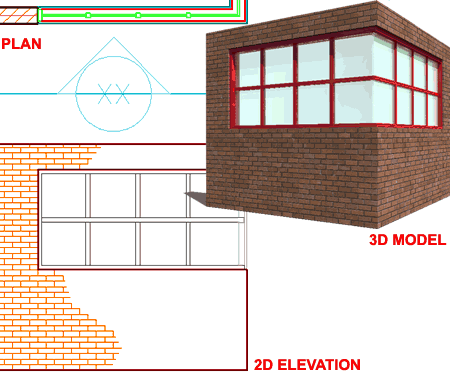
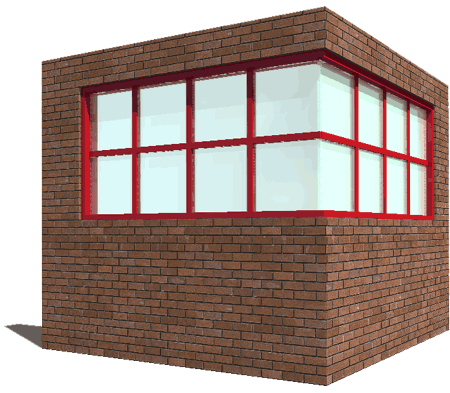
Despite all of the amazing tools and features in Architectural Desktop, some things as simple as a corner glazing unit can prove to be one of the most frustrating tasks you will come up against in this product. There are many logical explanations for why this task is a problem for ADT to solve but that really doesn't help designers who need to put something like this into their Plans, Elevations, Sections and even 3D Presentation drawings. In the discussion below I will outline one series of steps that you can take to create solutions similar to that illustrated to the right. Keep in mind that any solution is a "work-around" and thus open for debate among those who use Architectural Desktop. As always, I put more weight on Construction Documents than fancy 3D Renderings and thus this work-around attempts to produce good results in both cases.
You can use this information to work with Door/Window Assemblies and Curtain Walls in Architectural Desktop 3 through 2004. This example is based on Architectural Desktop 2004.
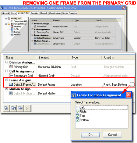
Assuming you have a fundamental knowledge about how to create Door/Window Assembly Styles (or Curtain Wall Styles), you will need to design a custom Style for the Corner Condition where one Frame Element is Removed.
Illustrated to the right I show how you can use the Frame Location Assignment dialog box to uncheck the Frame Edge where you don't want to see a Frame. In this example, the side I don't want a Frame Element for is the Left so I show that I have picked under the Used In column for the "Default Frame Assembly" row to access the Frame Location Assignment dialog box where I have unchecked "Left".
After you have completed the task of creating your custom Door/Window Assembly Style, Add this Style to your Corner Wall Condition as illustrated to the right. You should be able to Move the Assemblies right up to the edge of the Walls where they form a perfect corner but you will have trouble Moving them beyond this point since the Walls will want to maintain space for the Cleanup.
On the Properties Palette, use the Start or End Miter Angle value fields to set an appropriate Angle for the Miter between the two Assemblies. For those having some trouble with their math, the Context menu offers a simple Miter tool that will allow you to Select the two Assemblies for automatic Angle Calculation.
When you have the Miter Angles set, you should notice that the Assemblies project out beyond their original termination edge as illustrated to the right. All you have to do now it push the two Assemblies together and the Plan View for Construction Documents should be satisfactory. Not bad.
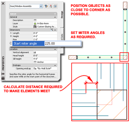
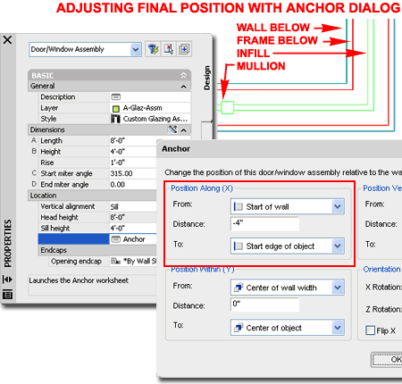
To force Objects that are Anchored in Walls to move past the default edge position, you will need to use the Anchor dialog box accessed through the Properties Palette as illustrated to the right. You will need to do this operation twice since the positions will be different for each Assembly.
By using the distance required to join the Assemblies at the corner ( see illustration above, right ), you should find that you can input that value for the Distance value field under the Position Along (X) section of the Anchor dialog box. Depending on the original direction of the Wall, you may need to use a Negative value. In tricky situations, you may even need to adjust the From and To options in order to better control how the Assembly Position is measured. It's not too bad to figure out with a few trial and error tests. The illustration to the right shows my values for the Assembly in the right-hand vertical Wall.
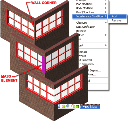
Once you have completed the Plan View portion of the work, you will probably want to take a look at the cool 3D Model View. This is where you will suddenly discover a new problem. Wall Cleanup Behavior is a bit wacky and you can't always trust what you see in Plan so here we find that there is a bit of Wall matter that we don't want.
This part is one that I really dislike dealing with because I still haven't come up with a simple solution that doesn't cause me some irritation later on down the road. You may want to explore other options but illustrated to the right I show a fairly simple brute force solution that most can follow.
By using the Mass Element tools in ADT, create a Rectangular form that fits right into the slot where there is extra Wall matter. Then, Select both Wall Objects, right-click, Select Interference Condition on the Context Sensitive pop-up menu and cascade over to Add. Select the Mass Element. For the Shrinkwrap plan effect question, use the "Subtractive" option. Turn off the Layer that the Mass Element is on and Viola, you should find acceptable results.
You can also use the Mass Element as a Body Modifier to Subtract with but by using the Interference option, you can accommodate design changes because you can always adjust the original Mass Element to match changes. Keeping the Mass Element on the Defpoints Layer is another option that avoids accidental Printing but invariably you will forget about it and make changes that will suddenly remind that you need it - hey, that's how work-arounds are.
Hopefully some of the information shared for this example exercise will provide you with some ideas for solving your own corner glazing conditions should you ever run up against them.
Remember that Door and Window Assemblies and Curtain Walls can use Window Styles as Infills providing you with more options for such things as Casement Windows at the Corner. Such Window Styles have to be designed with thought and typically do not have Frames or anything else that is better managed by the Assembly or Curtain Wall Style. Needless to say, I find all of this horribly tedious and irritating don't you?
For more information on Architectural Desktop 3 - 2004, make sure to look into getting one of our eGuides.
