PART 12
MODEL SETUPContents:
Model Setup - Overview ---- Linking with Xref's ---- Linking with Viz ---- Exporting to other Software ---- Customizing and Tricks
| Architectural
Desktop 3 - Presentation Guide PART 12 MODEL SETUPContents: Model Setup - Overview ---- Linking with Xref's ---- Linking with Viz ---- Exporting to other Software ---- Customizing and Tricks |
| 1Model Setup - Overview | 1-12 MODEL SETUP | ||||||||
| Architectural Desktop Objects and Display Representations Whether you manage your Rendering file as a set of Xref'd model files or as a copy of the original model files, the subject of how objects should look in these Renderings becomes just as important as it is for construction documents. Throughout this guide there have been numerous references to the task of Attaching Materials to Architectural Desktop Objects but there are other issues to consider. Some of these issues include the detail expected from these objects, the quality of the Material and how it is Mapped and how to structure the organization of these objects for better Material Management and Export to better rendering programs. If you keep a realistic focus on the end result of the Rendering and Presentation work then you should not face too many problems. Developing a sense of what is a realistic outcome takes a bit of experience and as your skills increase so too does the product you are able to deliver. Here are some things to keep in mind. |
What is the primary purpose of your work - construction documents or presentations to win a contract or convince a client of a concept. In Design Development Work my personal attitude is that anything goes as long as it serves the purpose of communication. This means that I don't really care how I produce the presentation drawings as long as they look great and meet the design criteria. If, on the other hand, you are already past design and in Development where the model files will also be used as the Construction Documents, then the less you "pollute" the primary files the better. In this situation I prefer to Xref files into a Rendering File where I will also add whatever props are needed to produce a good rendering. Eventually, the Xref's may have to be bound so Mapping can be employed for more realistic material placement, scale and so forth. When Working with Viz, I take the same approach. Keep in mind that the Rendering file is not the Construction Document and its purpose is to create an illusion much like Hollywood films do. You can do whatever it takes to get the scenes right. What is the purpose of your Rendering work - high quality photo-realistic renderings can consume an amazing amount of time and ultimately you end up fighting against the limits of your Rendering software. Consider the type of Rendering work required. I find that less realism is often better than attempts at super-realism because clients can often get distracted by materials, reflections, backgrounds and so on. Rendering time is also a major factor on what is possible and if you can't afford to have a machine render for one to five days then you shouldn't load a file up with that much attention to detail. |
||||||||
Accessing Entity Display Properties
The heart and soul of Architectural Desktop's Object Display is accessed through the Display Representations for each object. For this Guide and the subject of Rendering, we need to focus on the Model Display Representation as illustrated to the right.
The first level of Display Property management you can employ for Rendering and Presentation work resides on the Entity Properties dialogue box for each object type. By using the Display Manager or Drawing Setup dialogue box ( set to Display tab ), you can access the Model Display Representation for each object type and make changes to the way these objects should look in 3D Views or when a Display Configuration that uses the Model Display Representation is used. In other words, you may want to do a Rendering from a Top View so you will need to set the Display Configuration to Render or an equivalent Model Display Representation. |
 |
||||||||
| Entity Display Properties for Model
Display Representation The Display Props tab of most Architectural Desktop objects offers a drop-down list for Display Representations and three Property Source options ( ObjectName, ObjectName Style and System Default ). When you specify a Display Representation like Model, the three Property Sources are for that Display Representation only and thus you are free to make all sorts of changes that will not damage the Display Representations use for Construction Documents or other purposes.
Using Overrides is not a a terrible thing as the connotation of the word might suggest but it can lead to irritating problems when attempting to edit on a large scale. Work with System Default whenever possible; then use ObjectName Style and as a last resort, use ObjectName. |
 |
||||||||
Controlling Entity Display
Properties
Throughout these Guides I find that I am always drawn to using the Door object as my example case and it must be because of all the neat things you can so easily do to make a door look better. Windows, on the other hand can get so complicated that it will drive you crazy and Autodesk still hasn't gotten the basics of Window trim yet on those objects so why focus on them. So once more, let's look at a Door and see what we can do as an example of what can be done with many of Architectural Desktop's objects. Layer/ Color/ Linetype tab When you provide a unique Layer Name for each Component, these components will behave as if located on those Layers ( you can turn them on an off ) but they are actually still connected to the Insertion Layer of the main object so you cannot Attach Materials to these Layer Names.
You should also notice that I have a unique Component Name among the standard set and I called it "threshold". Actually, the name for this Component came directly from the Block Name used on the Custom Blocks dialogue box. This comes from the Other tab on the Entity Properties dialogue box and is where a lot of cool work is done for 3D Rendering and Presentation. |
 Other tab Note: |
||||||||
| Planning for Materials As your Renderings take on more realism and more Materials, you begin to discover that the organization of objects in the model files needs a structure that not only satisfies Printing for construction documents but for Rendering too. With Casework, for example, you may only need one or two Lineweights and Linetypes for construction documents but three or more Layers and/or Colors for Materials. Extreme care has to be taken so that objects don't end up with the same Materials unless intended. Using the Attach by ACI approach with Materials can be frustrating since numbers say nothing about object type and you will probably need to create a chart much like those created for plotter color tables. Many of the objects in Architectural Desktop were obviously not designed with Rendering in mind so you will have to consider how to work with these objects in situations where you must have Material variety on a single object. In the illustration to the right, I show a couple of Multiview objects from the Design Content section: a tub and ceiling fan. Neither of these objects have components and thus you cannot assign materials to different parts. If you are Rendering with Viz instead of AutoCAD or Architectural Desktop, you can attempt to work with these object by using sub-materials that are able to detect separate planes within a single object. If you are Rending in AutoCAD or Architectural Desktop, you can attempt to remedy this problem by using Refedit and simply separate the objects by some Color or Layer Name assignment. In desperate situations you can also Explode these objects. At times, I have turned off the Xref'd object and brought in a copy that is then exploded and modified just to get the scene Rendered correctly. For objects, like a ceiling fan, you may have to find a better 3D Model or create one yourself to get what you need in a Rendering. Walls - interior vs. Exterior - have you organized your model so that you can Attach unique materials to all walls that need unique materials. |
 |
||||||||
| Managing Hollywood Props In Rendering work a lot of props are often used in much the same way props are used on finished projects for magazine or advertising shoots. All of the same principals can be applied to a virtual shoot as a real one and you may want to add flowers in a vase on that cool oak table just to bring a little color into the Rendering. Adding things like this to the primary model has never made any sense to me and I always drop them into the Rendering file. I may even keep a stack of props off to the side and out of range for any Rendering Scenes that I can pick and choose from when setting up different Scenes. Props can vary in type from bitmap images like Landscape Objects to full models of background houses, trees and streets. You can acquire props from all sorts of places including your own library, on-line libraries and libraries from other software. As we have seen in this guide, you can even run out and take a digital picture of your coworker and have them in a Rendered Scene in minutes by using the Landscape Library so if you find yourself in need of props, they are all around you. |
|||||||||
| Importing from other sources There are many websites that cater to the 3D Studio Max crowd and new sites popping up these days for Viz users. These sites often offer files in .3ds format but that does not exclude AutoCAD or Architectural Desktop because there is a 3DSIN command specifically designed for importing these file types.
|
|||||||||
| 2Linking with Xrefs | 2-12 MODEL SETUP | ||||||||
The Rendering File as a Stew
In Part 11 - Reference we looked at the tools you can use to assemble a Rendering Model File with Xref's and some of the options that this process offers. Together with the discussion on automatic Material Attachments through a Rendering Template File in Part X - Appendix, the value of using the Xref system should be obvious. In this discussion, however, we will look at the potential problems and how to work with the Model Setup. Illustrated to the right, I show some of the "ingredients" that you might add to a Rendering File. The obvious files are the various plans that make up a typical architectural project: floor plan, furniture plan, ceiling plan, foundation plan and so forth. The other files may not be so obvious until you have done a few projects; these files can basically be anything you can get your hands on to improve the Rendering product. Most of the AecContent that comes with Architectural is so bad that it's embarrassing to use in Renderings but as will be discussed below, some simple things can be done to improve them a little. For higher quality objects that would likely never be used in the actual plans and construction documents, you can reach out to other software programs, AutoCAD Block Libraries, Architectural Desktop MvBlocks on Point A ( the website ), manufacturer libraries and all sorts of Web sites - see Links to other Sources in the Appendix. |
|
||||||||
| Working with the Source Files As you compile and refine the Rendering File, you will undoubtedly discover Object Representations that need to change for the particular Scene(s) you plan to Render. In order to achieve the desired results while maintaining Linked files, you will have to work on the source files. Illustrated to the right I show a proposed Scene to be Rendering on the left and the actual Floor Plan Model file on the right. In order to Modify how the Window Assemblies and Doors look in the Rendering File, for example, I have to make the changes in the Floor Plan Model file by working with the Display Representations of these objects. This is actually a fairly painless method of working so long as you can access the source file while the project is in development. There are times when the desired result(s) are just too time consuming or practically impossible to achieve in the source file. In cases like this you can simply model the desired effects in the Rendering File itself but once you begin this process, you also begin the process of breaking the definitive link. This is an inevitable process, in my experience. |
 |
||||||||
Deciding if, when and how to break the Links
A Rendering File will take on a complete life of its own and can easily become an extremely complex file ( often prone to crashes if the project is large ). At some point you will surely encounter the need to produce a better looking Rendering than can be achieved with linked files and the decision to break the link(s) will have to be made. Illustrated to the right I show an example of a scenario where the Xref'd Furniture Plan needs to be broken. By using the Bind command on the Xref Manager this can be a very easy task. Once the file has been bound, the Explode command can be used to access the individual objects within the former Xref. At times, however, you may need to go even further with the dismantling of the careful structure we tend to covet in typical CAD work.
|
 |
||||||||
| Exploding
objects Towards the final phase of a Rendering File you may end up breaking all of the traditional rules many AutoCAD and Architectural Desktop users have carefully crafted over the years because a Rendering File really only has one primary function: to produce knock-out presentation images. Just like Hollywood Studios, the goal is to get the shot and not to create a structure that will stand the test of time. The Xref's are used for as long as possible because remaining current with the actual design is very important but once you move past the need to worry about links, you may resolve to Exploding. Illustrated to the right I show a scenario in which a Furniture Plan has been Bound and Exploded to allow access to the individual objects. The individual objects are so poorly designed however that they too required Exploding to allow for changes that will make them more presentable. All AecContent ( MvBlocks ) can be Exploded down to their individual faces ( this usually requires two or more Explodes ). Once access has been established to the individual faces, they can be assigned unique Layers or Colors for Material Attachments - as illustrated by the chair, right. |
 |
||||||||
| 3Linking with Viz | 3-14 MODEL SETUP | ||||||||
| Autodesk® Viz 4 If you are
unfamiliar with Autodesk Viz, formerly known as 3D Studio Viz,
you can think of it as the next step in the As a Rendering program, Viz 4 is a gazillion times better than the Rendering program built into AutoCAD and Architectural Desktop. It has far superior tools for managing and presenting materials and lighting. In addition to being able to produce high quality Renderings with new radiosity based lighting, Viz 4 is also capable of producing animations. Whenever you prepare to take one file and port it out to another software program it is always wise to run tests with small samples to see what you will get and how to better manipulate all of the settings and options available. In addition to gathering information for the best method to port your files, also look for "bail-out" options in case something goes wrong. In the case of working with Viz, for example, you have several "bail-out" options: Rendering in AutoCAD or Architectural Desktop, Bind the Links or use non-linking methods like raw .dwg, .dxf and .3ds. For large projects, even Viz has Xrefs ( I will call them VizRefs ) so you can link several separate Viz files as needed for various shots rather than using one file for everything. |
|
||||||||
| AutoCAD
and Architectural Desktop Model Setup for Viz 4 Viz 4, where's the Architectural Desktop Information? Viz 4 and Architectural Desktop External References All objects become VizBlocks |
One
VizBlock or Many Attach several Files not one large
Xref File In this guide we looked at the process of automatically assigning Materials to objects and below we will look at how this automation can also be achieve in Viz. If you think about the work done to create a good Rendering Template file in AutoCAD and Architectural Desktop, you can probably translate these concepts to a Viz Rendering Template File. What comes through in a File Link So far I have yet to be successful at pulling through any Materials assigned in Architectural Desktop. AecCameras come through perfectly. Lights, like the Sun get changed to the closed matching Light and thus are often not what you want. I recommend not attempting to translate Lights. Complex AecObjects like custom Stairs with amazing detail on the balusters really slow Viz down; but then these also slow ADT down. Many primary objects like Walls, Doors, Windows, Curtain Walls, Wall Assemblies, Stairs, Railings, Roof and Roof Slabs are never "combined" but other objects like Columns and Mass Elements are. |
||||||||
Viz
- Layer Properties
One of the best improvements in Viz 4 is the adoption of more sophisticated Layer Properties as illustrated to the right. We will begin the discussion of Linking Architectural Desktop with Viz at the Layer Properties because this is where we can better understand the Attach Options available within the File Link Manager dialogue box - discussed below. Illustrated to the right, I show a Linked Architectural Desktop File that has been Attached with the Entity or one-to-one (no combining) option. As with Xref's in AutoCAD and Architectural Desktop, the Layer Names are preceded by the name of the file and a pipe ( "|") as a separator between the file name and the actual layer names ( as read in ADT ). Layers in Viz are more than just layers, they are also containers of VizBlock associations; much like Blocks in AutoCAD and Architectural Desktop have an insertion Layer. By expanding a Layer Name ( using the plus symbol ), we can read a list of all the VizBlocks associated with the Layer and we can actually control some display characteristics of individual objects ( like on/off and lock/unlock ). In the illustration to the right, for example, I show the A-Wall Layer expanded so that we can see all of the individual wall Entities in the current Viz file. Though this may seem like a simple concept, it isn't the only method for organizing linked objects nor is it consistent with all object types. Hence, the confusion begins when consistency does not appear to occur. Below we will look at each of the options available in the File Link Manager dialogue box with the intent of revealing how Viz treats ADT and non-ADT objects. |
 |
||||||||
Viz - File Link Manager - Attach Files
To create a Link between an Architectural Desktop Model File and Viz you use the File Link Manager dialogue box, illustrated to the right. This dialogue box is very similar to the one found in the previous releases of Viz though things have been reorganized a bit. The major new change from Viz 3 is the Presets option and how it has been designed to allow for saving Attach Options. This means that if you currently do not have Viz 4, the steps are still very similar in Viz 3 and Viz 3i. On the Attach tab of the File Link Manager dialogue box you will find the option to select the File to Link with, how to Attach those objects, what to Exclude and how to Scale the objects. File - this drop-down list acts as a history list for the last ten files you linked with but you can use the Browse... button to Select any new .dwg or .dxf files. Preset - this drop-down list will only offer options if you have created custom Presets on the Presets tab. These Presets are essential to acquiring a good link so it is best to create one before Attaching a file - see discussion on Attach Options below. Exclude Object by Layer... - this button reads the current file and offers the Layer Name list so you can specify which Layers you do not want Attached. This is similar to Freezing Layers in an Xref. Rescale - this checkbox and corresponding File Units drop-down list offers the opportunity to change the scale of the Attached File upon insertion. This means that if the AutoCAD or Architectural Desktop drawing was done in millimeters, for example, you can specify that you want it converted to Inches in the Viz file. This is not an option I am particularly fond of since having models at different scales can really make a job confusing. Attach this file - this button must be used at some point while in the File Link Manager dialogue box to Attach the current Model File. Close will simply save settings but will not Attach any new data. |
On the Files tab of the File Link Manager dialogue box you will find any currently Attached or Linked files, the condition of those files and options for Reloading, Detaching and Binding. These concepts should be familiar to anyone who uses AutoCAD's and Architectural Desktop's External References. Reload... - by highlighting any Linked File, you can use this button to force a Reload. Files listed with a red flag have been changed by the source program and require a Reload to be updated. Forced Reloads on files that have no red flag can often correct problems with files that appear to have loaded improperly. Detach... - this button can be used to remove any highlighted Linked file. Bind... - this button can be used to break the link of any highlighted Linked file so that it resides as true native objects in the current Viz file. |
||||||||
| Viz - File Link Manager - Presets On the Presets tab of the File Link Manager dialogue box you will find the most important settings and options of the whole file linking process. This is where you define how the objects will be handled as they are inserted and transformed into VizBlocks. If you have not created a Preset, use the New... button to Name a New Preset and access the File Link Settings dialogue box, illustrated to the right. On the Basic tab of the File Link Settings dialogue box, you will find a series of options very similar to the options on the Render dialogue box in AutoCAD and Architectural Desktop. These options are about the geometry. Weld - this checkbox activates an option that is similar to the Fillet or Union command for face vertices that adjacent according to the threshold distance. This is an option that is usually not necessary for AecObjects but more for sloppy surface modeling and its purpose is primarily to help Map Materials seamlessly with unified normals. Weld Threshold - this value field sets the distance between face vertices that should be welded. Welding will occur on distance equal to or less than that specified. Auto-smooth - this checkbox activates smoothing of faces based upon adjacent angles. This is exactly like the smoothing on the Rendering dialogue box in AutoCAD and Architectural Desktop but with the exception that this produce a physical result. Using too low an angle can produce facets where you may not desire them and too high a value may produce too much curvature ( not enough facets ). The only way to really tell if the angle requires changing is if you observe a need for an adjustment. Smooth-angle - this value field sets the angle between adjacent faces that will be smoothed. Smoothing will occur on angles equal to or less than that specified. Unify Normals - this checkbox activates an algorithm that attempts to determine the correct orientation of faces based upon adjacent faces. This is an important aspect for proper mapping of Materials because it sets the direction based upon a front or back side. For Architectural Desktop objects this does not seem to present itself as a problem nor is it necessary on Solid objects but it can prove to be a problem on Surface objects. You can determine face normal problems in a Rendering when materials appear to disappear. One of the tricks to solving this problem is to Render with the 2-Sided option. I tend to leave this option on and have not found that it causes any problems, though it is recommend that this option be unchecked when working with Solid object. Cap Closed Objects - this checkbox activates automatic capping of closed objects that have been given a Thickness value ( which provides a Z-axis height to 2D object ). The capping amounts to faces where none exist so that the objects appear to be solid and not hollow. Curve Steps - this value field determines how many segments to use between control points on a Spline. A higher value creates a more accurate curve. ACIS Surface Deviation - this value field affects the faceting of Solids. Smaller values create more accurate surfaces. |
 Reload On the Advance tab of the File Link Settings dialogue box you will find the most important options for the file linking process. This is where you define the relationship between the AutoCAD and Architectural Desktop objects and Viz. Be sure to keep a clear distinction between AutoCAD objects and Architectural Desktop AecObjects because the results of these options affect the objects differently. Resolve External References (xrefs) - this checkbox can be used to indicate that you want all Xrefs of the current drawing file to be Attached as well. The problem with this option is that you have no control over how the "resolved" Xrefs are Attached and they come in as a single VizBlock. Working with a single VizBlock, even if it is an entire floor plan, is not the end of the world but requires a refined approach to Material Attachment and Scaling - see Multi/Sub-Object Materials below. Skip Hatches and Points - this checkbox offers the option to include or exclude hatch patterns and points which could add quite a bit to the file size and may not be desirable in the first place. Attach Options - see discussion below Add Origin Point Helper - this checkbox can be used to have Viz insert a UCS icon at the origin. Though it can be useful for alignment purposes, I find it very annoying when using the Zoom All command in Viz. Reload Options Reset AutoCAD Object Thickness - Resolve all Xref Paths Again - this option can be used if the paths have changed for Linked files with Xref's in them. |
||||||||
| Viz - File Link Manager - Presets - Attach Options Attach Options Layer - AutoCAD: all objects sharing the same Layer Name will be "combined" into one VizBlock residing on one VizLayer. Architectural Desktop: some objects sharing the same Layer Name will be "combined" into one VizBlock residing on one VizLayer as an associated Layer object. Most ADT objects are not "combined" with this option. Color - AutoCAD: all objects that share the same Color Property will be "combined" into one VizBlock. Objects assigned Color by Layer will be "combined" by that Color. Objects assigned a unique Color will be combined by that Color. Objects with complex structures like Blocks, will be "combined" by the primary color assignment. This means that a multi-colored block will come in as one object based on its Color Property. Architectural Desktop: some objects sharing the same Color Property will be "combined" into one VizBlock residing on one VizLayer as an associated Color object. Most ADT objects are not "combined" with this option Entity - this option was formerly known as "one-to-one no combining" which really defines what you get for both AutoCAD and Architectural Desktop objects. All objects will become unique VizBlocks residing on translated VizLayers as associated Layer objects. One Object - AutoCAD: all objects are "combined" into one VizBlock residing on one VizLayer. Architectural Desktop: some objects sharing the same Layer Name and/or Color Property will be combined in the same way as by Layer and/or by Color. Most ADT objects are not "combined" with this option. |
|
||||||||
| Viz - File Link Manager - Rendering On the Rendering tab of the File Link Manager dialogue box you will find options that are only for Linework and not 3D geometry. Since Viz can work with basic AutoCAD objects as a source for modeling, these options can be very valuable. Shape Rendering (Lines & Splines) Thickness - this value field can be used to provide a 3D diameter for Lines and Splines. Sides - this value field can be used to set the number of facets for the outside of the cylinders created by the thickness value. Angle - this value field rotates the cylinders created by the thickness value and can be used to align a side ( as set by the sides value ) with a direction. |
Renderable - this checkbox determines if the settings are rendered. Generate Mapping Coors. - this checkbox will create mapping parameters for materials where U maps the circumference and V maps the length. Display Render Mesh - this checkbox determines if you see the cylinder mesh or not. Use Viewport Settings - this checkbox determines if you want to use the Viewport radio button and consequent settings or those settings for the Renderer. You can essentially have two completely different sets of settings; one for the Viewport and one for the Renderer. Update in Viewports - use this button to push the current settings to the current viewport regardless of whether they are for the Viewport of Renderer. |
||||||||
| Viz - File Link Options and Selecting Once you have Linked and Attached an AutoCAD or Architectural Desktop file, you can use the Select By > options to work with those objects. For AutoCAD objects, the type of Combining you used will dramatically affect the Select By results. For Architectural Desktop's AecObjects, the Combining does not have the same level of affect so the Select By results remain much the same. The Select by options, however, are ideal for AecObjects since they are generally organized by Color, Name and Layer. If you wish to Assign a Gyp. Board Material to all Walls in a Linked scenario, you can Select By Layer "FileName|A-Wall". The only Combination type that does not allow this type of Selection is the the "One Object" type where all AecObjects reside under one Layer Name. In this scenario, you can use the Select By Color or Name options. |
 |
||||||||
Viz - Display and Automatic Materials
Once an Architectural Desktop file has been Attached, the appearance may be a bit confusing at first due to some default settings in Viz 4. As discussed above, not only does Viz 4 manage AecObjects in a very unique way when Linked but it also Maps materials and applies Mapping Coordinates automatically.
Illustrated to the right, I show the Material/Map Browser Window with the default "ADT.mat" Material Library Open. These are the default Materials that are automatically mapped to your Architectural Desktop objects when they are Attached via the File Link Manager. In reality they are not actually Material but just the building blocks for Materials. You may notice that they are all "Multi/Sub-Object" Material types particularly useful for complex AecObjects like Curtain Walls, Stairs, Railings, Doors and Windows. If you Edit any of the default Materials, you will find that they are all based on a generic shade of gray. They have been created to make your life easier so long as you understand the concept of a "Multi/Sub-Object" Material. Once you figure this structure out, you can edit all of these default Materials, set personal colors and parameters and save them. If you Rename the ADT.mat file before editing the this file, you can Save the Edited file as ADT.mat and have a new automatic Material file that comes ready to go with Wood, Metal, Glass, Concrete and so on. |
 |
||||||||
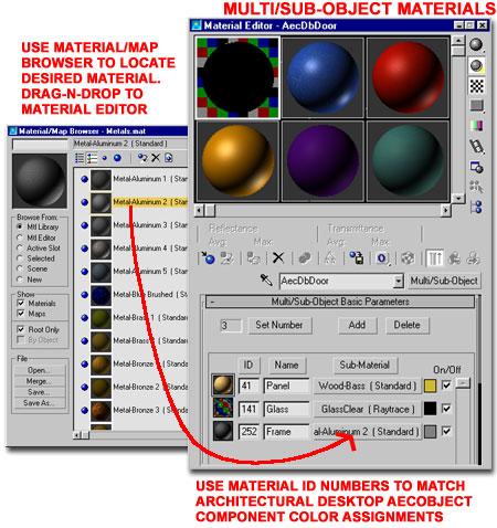
Viz - Multi/Sub-Object Materials
All of the default Architectural Desktop Materials automatically assigned by Viz are set for 10 Sub-Materials which is usually far too many slots most AecObjects. You can calculate the number of Sub-Materials required by counting all of the components listed for any AecObject on the Layer/Color/Linetype tab of the Entity Properties dialogue box. You can also use trial-n-error test by viewing the Material in Shaded Mode on the object you are working with. Multi/Sub-Object Materials are specifically designed to work with complex objects that are contained within one Vizblock. This means that you could actually create one Material with 255 slots that holds all of the Materials for all of the Colors used by Architectural Desktop on a typical Model. And, this is exactly how some people manage Resolved Xref Files brought in with the File Link Manager. The key to success with these amazing Materials is getting the order of the Sub-Materials to match the order of the objects they are assigned to. Though it is not required, the easiest way to achieve the matching is to specify the Components Color Numbers in the ID value fields. Illustrated to the right, I show the default Door Material "AecDbDoor" and the three Sub-Materials I have chosen for a typical glazed door. I used the Set Number button to specify that I only wanted three slots. I used the Material/Map Browser Window to Open Library Materials that I then dragged and dropped on top of the Sub-Material buttons. By reading the Component Colors for the Door, I was able to specify the Color Number ( ID ) for each Sub-Material so they would be assigned to the Colors of the Components. For the Name fields, I simply typed in the Door Component Names so I won't forget what I have done. |
 |
||||||||
| 4Exporting to other Software | 4-2 SHADE | ||||||||
File Types for other Software
Autodesk Viz is not the only alternative Rendering program available on the market and may not necessarily be the best for your needs - though it is difficult to argue against the value of File Linking. But even with Viz you can exercise Export options from AutoCAD and Architectural Desktop. Since 3D Studio Max has become a major broadcast quality Rendering and Animation program, the .3ds file format is almost as ubiquitous as the .dwg file format. As it turns out, AutoCAD and Architectural Desktop can write .3ds files which can not only be OPENed by Viz and Max but also by other presentation programs on the market that support the .3ds file format. |
In addition to the .3ds file format, you can Export to the nearly universal .dxf file format which can be Opened or Imported by nearly every vector based program on the marked these days. To create a successful Export from Architectural Desktop, be sure to export while using a Display Representation that displays 3D geometry; something like the default Model or Render Display Representations. If you experience any problems with Architectural Desktop files that have been exported, you can use the AecObjExplode command to convert all of the AecObjects into Surfaces. Make sure that you don't do this to the primary file but a copy of it. You can read about AecObjExplode in the Development eGuide. |
||||||||
| 5Customizing and Tricks | 5-2 SHADE | ||||||||
© Copyright 2002 ARCHIdigm. All rights reserved.
spell checked on Jan. 24, 2002
 Illustrated to the left, is another way to access
the Display Props tab; select the specific object,
right click on your mouse to invoke the object-specific pop-up menu and
select Entity Display... See discussion directly below.
Illustrated to the left, is another way to access
the Display Props tab; select the specific object,
right click on your mouse to invoke the object-specific pop-up menu and
select Entity Display... See discussion directly below.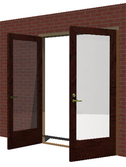 Using Color Assignments for Components is the best way to manage
Material Attachments in Architectural Desktop because you can use the By ACI... option on
the Materials dialogue box to manage the Attachments. The problem is that you only
have 255 Colors to work with and you have to track numbers rather than Layer Names.
I compromise by using Colors for Components but Layer Names for the primary object;e.g., I
Attach Wood to A-Door Layer but Glass and Chrome to the Component Colors for the Door
object.
Using Color Assignments for Components is the best way to manage
Material Attachments in Architectural Desktop because you can use the By ACI... option on
the Materials dialogue box to manage the Attachments. The problem is that you only
have 255 Colors to work with and you have to track numbers rather than Layer Names.
I compromise by using Colors for Components but Layer Names for the primary object;e.g., I
Attach Wood to A-Door Layer but Glass and Chrome to the Component Colors for the Door
object.
 Rendering process. This program is a spin-off
of 3D Studio Max and targeted at design professionals; particularly those
who use Architectural Desktop. It comes complete with a File Link Manager
that has been designed specifically to accept AecObjects while allowing you to continue
working on your project in Architectural Desktop. Below we will discuss some of the
primary aspects of creating and managing Links with Viz 4's File Link Manager.
Rendering process. This program is a spin-off
of 3D Studio Max and targeted at design professionals; particularly those
who use Architectural Desktop. It comes complete with a File Link Manager
that has been designed specifically to accept AecObjects while allowing you to continue
working on your project in Architectural Desktop. Below we will discuss some of the
primary aspects of creating and managing Links with Viz 4's File Link Manager.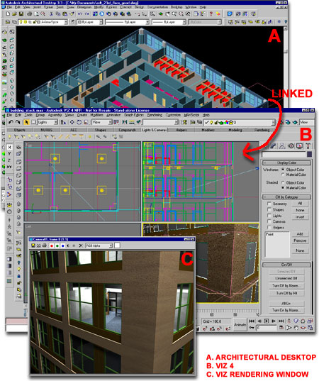
 If
you wish to see your Architectural Desktop objects much as they would look in
Architectural Desktop, you can use the Display Color options on the Display tab of the
Command Panel. If you set Shaded, for example, to Object Color then Viz will display
all of your Architectural Desktop objects as they would look in ADT ( without Materials ).
If
you wish to see your Architectural Desktop objects much as they would look in
Architectural Desktop, you can use the Display Color options on the Display tab of the
Command Panel. If you set Shaded, for example, to Object Color then Viz will display
all of your Architectural Desktop objects as they would look in ADT ( without Materials ).