PART 4
OPTIONS DIALOG BOX - ARCHITECTURAL DESKTOP SETTINGSContents:
AEC Editor Tab ---- AEC DwgDefaults Tab ---- AEC Performance Tab ---- AEC Stair Defaults Tab ---- AEC Content Tab ---- AEC Dimensions Tab ---- Structural Memebers Catalog
| Architectural
Desktop 3 - Deployment eGuide PART 4 OPTIONS DIALOG BOX - ARCHITECTURAL DESKTOP SETTINGSContents: AEC Editor Tab ---- AEC DwgDefaults Tab ---- AEC Performance Tab ---- AEC Stair Defaults Tab ---- AEC Content Tab ---- AEC Dimensions Tab ---- Structural Memebers Catalog |
| 1AEC Editor Tab | 1-4 ARCHITECTURAL DESKTOP SETTINGS | ||||||||||
AEC Editor
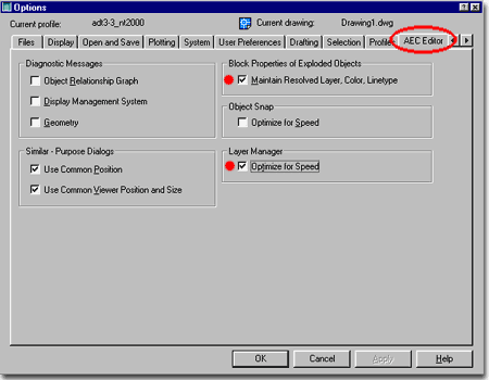
Basically the default settings are set for optimum performance so you may not need to change anything here at all. One of the worst mistakes that "half-savvy" users often do is check the "Optimize for Speed" under the Object Snap option and end up complaining that Architectural Desktop doesn't Osnap to objects it used to; well, duh. But they forget what they played with and thus it becomes the CAD Manager or IT persons problem. Of the whole set here, I like the ones checked as illustrated to the right but I'll go down the list and explain what they do. Diagnostic Messages Display Management System - see comments above Geometry - see comments above. Similar - Purpose Dialogs Use Common Viewer Position and Size - this option is supposed to control the little Object Viewer Window that is available on the Add, Modify and Style dialog boxes. My test did not provide conclusive evidence that this option does much but it may on your system. Recommended. |
 Block
Properties of Exploded Objects Object Snap Layer Manager |
||||||||||
| Note: When making changes to the various Settings on the Options dialog box, it is often necessary to shut the program down and restart before the changes take effect. |
|||||||||||
| 2AEC DwgDefaults Tab | 2-4 ARCHITECTURAL DESKTOP SETTINGS | ||||||||||
AEC Drawing Defaults
The drawing icon next each of the Options within the whole Options dialog box indicate that the settings are only specific for the current drawing and thus do not get saved as part of the Profile configuration. This means that on one level of the Network Customization, these settings can all be ignored. It also means, however, that these settings will have to be addressed at a later time for the Template file creation. Skip for the Profile Configuration but return for the Template File Creation
Dimension to Outer Frame of Opening - see comment above. This will run Dimension Extension Lines to the outside of Frames which will result in "Rough Frame" opening dimensions and not the more common finished opening dimension so you may prefer to use the Center option or remove the Frames from Doors and Window objects. Use Center Line as Graph Line - setting this option basically contradicts the default structure of baselines within Wall Styles and is thus highly discouraged as an option. If Centerlines are desirable for the graph lines, Walls should be drawn Justified as such. Autosnap New Wall Baselines - this option controls how Walls behave when you get them near each other. Having the Autosnap feature active helps to get Wall to auto-cleanup because they will connect within the Radius specified on the Autosnap Radius value field. Autosnap Grip Edited Wall Baselines - this option helps to emulate the effect of what the Autosnap New Wall Baselines achieves when Wall are being drawn. In other words, once a Wall has been drawn but was moved away from one it used to clean up with, this value will produce a similar Autosnap when the Grip Stretch tool is used. This option uses the Autosnap Radius value as well. Autosnap Radius - this option sets the distance the graph line of a wall object will travel beyond a picked position when detecting another wall object. Wall Cleanup Radius - since the Autosnap Radius is the first attempt at getting walls to cleanup properly, adding a Cleanup Radius is somewhat redundant. Therefore, the Wall Cleanup Radius should be set to zero by default. It can be changed for Walls that have special problems on an as needed basis via the Override Wall Cleanup Radius tool. Wall Styles also have an independent option for a default Cleanup Radius. Space Settings |
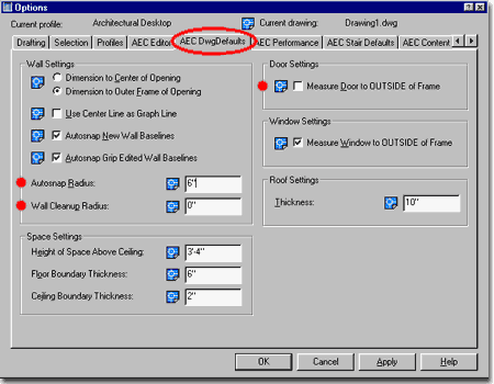 Door Settings Window Settings - if checked, this will create Windows to be the Width specified in the Window Width Value Field of the Add Window dialog box. Since this is quite regular for Imperial Based Architectural practice, the consensus is to leave this checked. Roof Settings |
||||||||||
| 3AEC Performance Tab | 3-4 ARCHITECTURAL DESKTOP SETTINGS | ||||||||||
AEC Performance options
The Wall Display options listed on this tab are not part of the Profile settings but rather part of an individual drawing file and thus are more of a topic for template files than deployment. These settings can thus be ignored for the Installation and Deployment process but will need to be discussed for the template files. As part of a Template File, chances are that you will not want any of these options checked because they are basically overrides of normal Wall or Wall-related display characteristics. In cases where you are attempting to solve drawing file problems by overriding settings or trying to track down a Wall Display problem this might be used in a specific file. These options have also been provided to help file performance by reducing the load on display work that ADT has to do every time a drawing is worked on or opened. In other words, not cleaning up intersections, not displaying hatches and not cutting openings for doors and windows can really make a file run faster. The problem is that it's pretty hard to find user mistakes if these options are checked. I never use them. Never Cleanup Wall Intersections - walls are usually cleaned up so this would be a rare option to select. Each time a file is opened, wall intersections are recalculated so this option can be used to increase performance.I find, however, this is more of a problem than a feature since getting proper wall cleanup is a task requiring constant monitoring. Never Hatch Wall Components - this might be used as an override when removing hatching is too problematic or a user has inadvertently added incredibly dense hatches to walls. Again, it can be used to make a file run faster. |
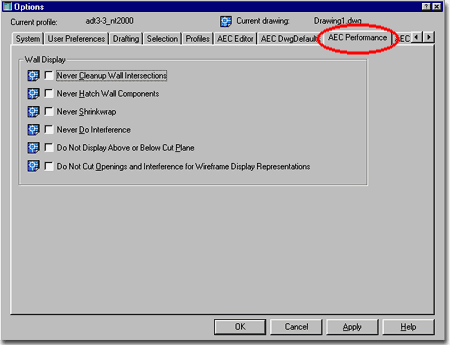 Never Shrinkwrap - this option addresses how Wall Styles, that have Shrinkwrap turned on, display when other objects are merged into them, for example. Shrinkwrap is the outer line that is usually darker and thicker than internal components. This option can be turned on or off within any Wall Style. This does not seem to affect performance that much. Never Do Interference - this option addresses the ability to use other objects as interference conditions on Wall Objects often resulting in unique wall shapes with an outer Shrinkwrap effect. If Interferences have been used, this option might be useful to uncover them. This will increase performance but could be problematic since users may not be looking at what they really have created. Do Not Display Above or Below Cut Plane - Wall Styles have a cut Plane setting that determines the reference plane of what lines are below and what are above in certain Display Configurations. This does not seem to affect performance that much and is more dangerous than anything. Do Not Cut Openings and Interference for Wireframe Display Representations - the few times that I have actually gotten this option to work correctly, time has been reduced when changing 3D displays but since I could not get it to run consitently, I am not convinced of its value. |
||||||||||
| 4AEC Stair Defaults Tab | 4-4 ARCHITECTURAL DESKTOP SETTINGS | ||||||||||
AEC Stair defaults
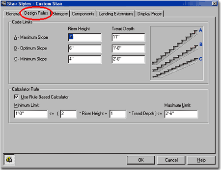
The AEC Stair Defaults options listed on this tab are not part of the Profile settings but rather part of an individual drawing file and thus are more of a topic for template files than deployment. These settings can thus be ignored for the Installation and Deployment process but will need to be discussed for the template files. Stair Styles can override many of the settings on this tab; see discussion below. Be aware that though these are listed as Defaults, some of the settings do not appear to carry through to New Stair Styles as they should and you may have to change these "defaults" on the individual Stair Properties after creation. I have listed those settings that do not appear to carry through correctly below. Presentation Format ( No Cut Line or Path ) - checking this option will draw stairs as they would appear in reality instead of how we typically show them in architectural construction documents. This is an unusual option and is rarely used. Node Osnap - though the two options "Flight & Landing Corners" and "Vertical Alignment" should provide very different Node Osnap points on Stairs, we found little difference between these two options and thus recommend leaving it at the default "Flight & Landing Corners". Measure Stair Height - though there are two options for this measurement, I have found that measuring by "Finished Floor to Floor" works find if users do not add Offset Values to Stair Properties on the Constraints tab. Given that ADT really does not offer a method for accounting for floor components yet, I feel it is best to consider all of these measurements as either rough or finished, regardless of what the dialog boxes might infer. The other measurement option is "Rough Floor to Floor" and is supposed to ignore any Offset Property Values user might input, but our tests find that it does appear to read the offset values as well. Code Limits Optimum Slope should be set to what you would like in a best case scenario and that could be the same as Maximum Slope if you prefer. In the illustration to the right, I set it to 6" ( 180 ) and 12" ( 270 ) as an example for a possible exterior concrete stair. Minimum Slope should be set to handle the minimum Riser Height allowable and the maximum Tread Depth you would use for this particular style. Keep in mind that the Tread Depth value you specify here will limit your Tread Depth value on the Add Stair dialogue box ( with or without the Calculator Rules active). Flight Height Limits Minimum - use this number field to set a value for Riser Count or Height Value when using a Limit. |
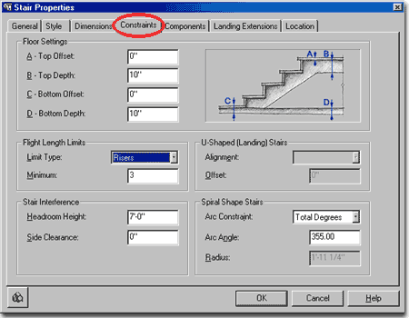
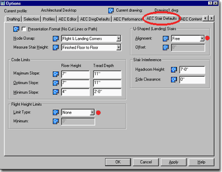 U-Shaped ( Landing ) Stairs Offset [does not appear to work correctly] - The distance you want your up Treads or Risers to vary from your down Treads or Risers with respect to the Alignment option. If you use Tread to Tread for an alignment, for example, and use 0" for the Offset value, then the Stairs should match on both sides of a U-shape. Use a positive number and the up flight moves forward of the down flight. Use a negative offset and the up flight moves backwards towards the landing with respect to the down flight. Be aware that as you move the up flight back and forth, the down flight will compensate with the gain or loss of an additional riser and the landing may also be adjusted to compensate for this change. Also, keep in mind that the down flight ( down from the landing to the floor ) remains static with respect to the insertion point while the top riser of the up flight will move freely. Stair Interference Side Clearance - This is the amount of offset you want when using the Space Interference command to automatically cut a hole based on the Stair object's Headroom Height ( discussed above ). In other words, if you want the hole to be greater than the width of your stairs, put that value in here. |
||||||||||
| Stair Styles - Design
Rules tab Illustrated to the right I show how some of the settings discussed above are also available on the Stair Style dialog. The defaults simply help users start new Stair Styles but some settings, such as "Presentation Format ( No Cut Line or Path )" are not defaults but a complete adjustment to all Stair Styles. |
 |
||||||||||
| Stair Properties -
Constraints tab Illustrated to the right I show how some of the settings discussed above are also available through the Properties dialog on individual Stair objects. |
 |
||||||||||
| 5AEC Content Tab | 5-4 ARCHITECTURAL DESKTOP SETTINGS | ||||||||||
AEC Content Folder
Search Path
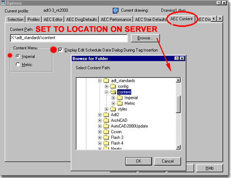
On Networked installations, all of the AEC Content folders should be moved and pathed over to a central location on the server - as discussed in Part 1 and 2. For Architectural Desktop, the Files tab does not provide an option for setting the search path for the AEC Content so you will have to use the Content Path statement here on the AEC Content tab of the Options dialog box ( as illustrated to the right ). The path should be set to the "Content" folder and not the Imperial or Metric subfolders. Content Menu - the two radio buttons for Imperial and Metric can be changed at any time during a an active session to force the DesignCenter to switch to the Imperial or Metric Content Folders. This can also be achieved simply by going to the Imperial or Metric folder once the DesignCenter has been opened. Set this to match the majority of work done in your office. Display Edit Schedule Data Dialog During Tag Insertion - this checkbox is a really good option because if it is unchecked, users can attach schedule tags a lot faster without having to go through the Edit Schedule Data dialog for every tag. Recommend that this option be unchecked after users are familiar with Tags and Schedules. |
 |
||||||||||
| 6AEC Dimensions Tab | 6-4 ARCHITECTURAL DESKTOP SETTINGS | ||||||||||
| AEC Dimension defaults -
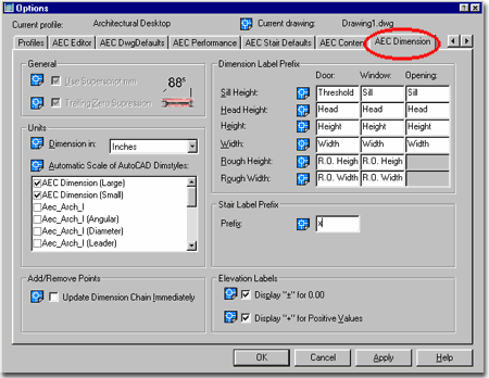
[ International Extensions ] The AEC Dimension options listed on this tab are not part of the Profile settings but rather part of an individual drawing file and thus are more of a topic for template files than deployment. These settings can thus be ignored for the Installation and Deployment process but will need to be discussed for the template files. If you have decided to use the AEC Dimensions from the International Extension package that is offered when you first install Architectural Desktop 3.3, you can use the AEC Dimension tab to make some minor adjustments to some of the labeling features. The General area is only available to those using the Millimeters Unit setting from the Dimension in drop-down list and basically offers the option to use the superscript "mm" and/or suppression of zeros. Automatic Scale of AutoCAD Dimstyles - this option will scale AutoCAD Dimension Styles if a user changes the Drawing Setup Units from something like Inches to Millimeters, for example. All AEC Dimension Styles use AutoCAD Dimension Styles. Update Dimension Chain Immediately - this option refers to the AEC Dimension editing tools for adding or removing points for extension lines. In my opinion, checking this option is superior to having extra steps to deal with. Dimension Label Prefix - these titles refer to the labels you can insert on Doors, Windows and Openings but most are not used by the default labels that come with ADT. For the Door Label, for example, only the Head Height label is used unless you develop your own MVblocks to use other Prefixes. Documentation pull-down menu > Dimension Labels Stair Label Prefix - this option refers to the prefix you want on the labels for Stairs; such as 6x 1'-6/2'-4 or 6 Risers 1'-6/2'-4. The x is typically okay. Elevation Labels - these two options refer to the datum label markers users can place in a drawing to report 3D Elevations. Documentation > Documentation Content > Elevation Labels. Leave these two checked unless your office standards call for something different. Chances are that these symbols will not be used anyway. |
 |
||||||||||
| 7Structural Members Catalog | 7-4 ARCHITECTURAL DESKTOP SETTINGS | ||||||||||
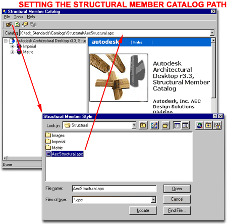
Structural Member
Catalog Path
The Structural Member Tools in Architectural Desktop rely upon Member Styles as derived from the Structural Member Catalog - illustrated to the right. This Catalog, reads data tables from an .xml format and thus uses a Browser-like interface to help users select member types and sizes. Setting the path by typing it in on the Catalog drop-down list or by using the Open file dialog box, illustrated to the right, will save the path for the current installation only but will not be saved as part of the Profile and thus you will have to confirm this path for all workstations independently. |
 |
||||||||||
© Copyright 2002 ARCHIdigm. All rights reserved.
spell checked on Oct. 19, 2002 (gr)