Architectural Desktop has a fairly good Railing tool but when it comes to creating rather unique designs, the work can often prove perplexing. In developing the Architectural Desktop Fence Kit, just released, we at ARCHIdigm have explored the process of inserting all sorts of crazy things into Railing Styles and in this article we'll share one of the most requested options. If you really need this X-brace Railing Style but don't have the time or energy to learn how to make it, you can buy it and numerous other Railing Styles for only $20.00 - that's gotta be less than the hour it will take you to figure all this stuff out.
All kidding aside, knowing how to create custom inserts for the Railing Style is a rather useful bit of knowledge because it will not only allow you to create great Railings but also Fences and anything else that uses a simple repetitive linear element ( lamp posts, trees, etc.).
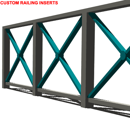
Illustrated to the right is a common X-brace insert within a common 36" high guardrail. Below are the steps used to create this Railing Style and though it was written for Architectural Desktop 4 ( okay, they call it 2004 but it's just 4 to me - in fact, it's just plain old ADT 4 to me ), the steps apply to ADT 3 - 3.3 as well.
In case you are wondering about ADT 4, there are a few little improvements for the Railing Style but not enough to blow your hair back.
Once you have create a New Railing Style, go ahead and Edit it.
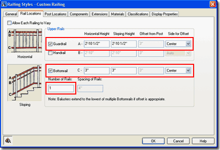
Illustrated to the right you should see that I have created a New Railing Style that I called "Custom Railing" and am in the process of setting the values for the "rails".
Since this is a very simple example, I am only using the Guardrail and Bottomrail components; the Handrail component has been unchecked. For the Guardrail, set the Heights to the top of the Posts by subtracting the height or Depth of the actual Guardrail Component. Illustrated to the right I show 2'-10 1/2" for a Height because my Guardrail will be 1 1/2" thick. Note: this is only true for ADT 4 where new Justification options are available so for ADT 3 set the height to the full physical height of the railing.
For the Bottomrail, set the Heights to the Center Depth of the actual Bottomrail Component ( yet to be set on the Components tab ). In this example I am only using one ( 1 ) Rail.
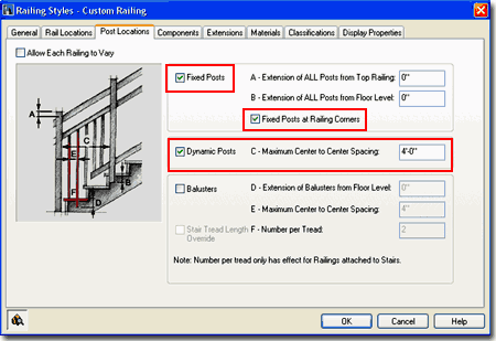
On simple railing designs, the Posts are fairly easy to configure. Illustrated to the right I show that I have checked "Fixed Posts" , "Fixed Posts at Railing Corners" and "Dynamic Posts". There will be no Extension of the Posts and no Balusters but you will need to set the "C-Maximum Center to Center Spacing" for the Dynamic Posts so the Custom Insert will fit properly. I am using 4'-0" in this example but feel free to use any value you want.
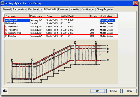
Keeping in mind the Components that we checked on the Rail Locations tab, you will not need to configure all of them.
Illustrated to the right I show that I am only concerned with the settings for the Guardrail, Bottomrail, Fixed Posts and Dynamic Posts.
For this example I am using all Rectangular Profile Names and have set Widths and Depths based on a steel design but it hardly matters what you set here.
In Architectural Desktop 4 you can now use the Justification drop-down options to position the Components relative to an imaginary plane through the center of the posts ( this is similar to a baseline on Walls ). For the Guardrail, I show that I have used the Bottom Center Justification to place it right on top of the Posts. In ADT 3 the Posts would run up through the Guardrail but now they actually stop at the proper position.
Simply design your Railing Style as you see fit and move on through the other tabs all of the way down to the Display Properties tab.
Extensions tab - only applies to railings to be attached to stairs.
Materials tab - new for ADT 4; allows for direct assignment of hatch patterns and rendering materials to components but is far too convoluted a system to add to this discussion and is not entirely necessary to produce successful custom railing styles.
Classifications tab - new for ADT 4; allows for classification of objects in new categories such as "Existing", "Proposed", "Phase 1" and so on but is also too convoluted to add this discussion.
In order to proceed with the Display Properties settings, you will actually need to OK your way out of the current custom Railing Style and do some design work before coming back to finish. This last part is where the real magic occurs.
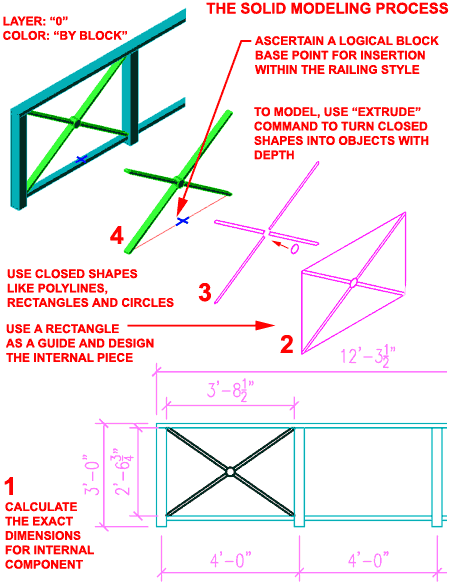
Illustrated to the right is an example of what I am striving to create and the preliminary steps required to get there. By this time I should have a fairly simple railing, illustrated in cyan, with no insert. The insert is what we have to design and model.
Step 1
Illustrated to the right in Step 1 I show the true dimensions of my Railing Style in
Elevation View. In order to design a successful insert, I will need to create a Rectangle
that matches the interior space where I want the insert to be placed. If the
proportions are not matched, the insert may end up rather distorted.
Step 2
In Step 2 I show how a rectangle can be use to draw diagonal linework
that can be used to create the final design for the insert. You can draw this in
Plan or Top View but it is best if you draw it in Front, Left, Right or Back Elevation
Views because we will need it to be standing up when we make a Block out of it. Do
not attempt to draw right on the Railing itself because the lines will often end up
non-planar with the UCS and that will prevent you from using the Pedit command or even the
Boundary command.
Step 3
In Step 3 I show how my diagonal brace design is actually made up of five closed
shapes: four spokes and one circular centerpiece. You could, of
course have two diagonal closed shapes and one centerpiece as well. The key here is
to make sure that the linework is closed.
Step 4
In Step 4 I show that I have used the "Extrude" command from
AutoCAD's Solids tool set. I set the Extrusion value to the depth I wanted my
diagonal braces and extruded them separately from the center circle. For the Circle,
to give it a little design appeal, I extruded it a little more than the braces. Once
complete, I show that I have chosen a bottom center spot as the Block
Insertion Point.
When you have completed the 3D Model, which by the way, could also be created with Mass Elements, Structural Members, Surfaces or whatever other creative solution you can come up with, you must use the "Bmake" command to create a Block of the 3D design. When you make the Block, make sure that the UCS icon is in World and that the 3D insert is standing up as illustrated to the right. If you don't do this part correctly, the insert will end up lying sideways within the Railing Style.
Having completed the 3D Modeling and Block steps outlined above, you can return to the Railing Style and go directly to the Display Properties Tab.
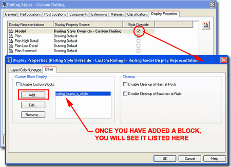
Since Railing Styles are fairly simple, you should find that you will only need to work with the Model Display Representation for the 3D Views and for Elevations and Sections.
Illustrated to the right, I show that I have checked the Style Override option so that any changes I make for this Railing Style will only affect this Railing Style and not all Railing Styles.
On the Display Properties (Railing Style Override - ...) dialog box for the the Model Display Representation, I show that I have skipped past the Layer/Color/Linetype tab and gone straight to the Other tab where you will find that you can use the Add... button to add the custom Block created earlier.
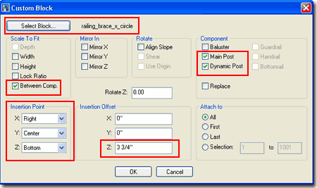
On the Add Block dialog box, use the Select Block... button to select the Block Name created earlier.
Though there are all sorts of options for working with custom Blocks, for this example what you will want to do is use the Between Comp. option under the Scale To Fit area. Under the Component area you will want to check the Main Post and Dynamic Post. By using these settings, you will force the Block to always pop up between the Main Posts and the Dynamic Posts along the inside.
For the Insertion Point, you may need to play with these to get it right for you own exercise but for the example I am using here, X=Right, Y=Center and Z=Bottom but with a slight positive adjustment to the top of the Bottomrail. Insertion Offset for Z=3 3/4".
Note:
For inserts, it is very important that you get the X=Right setting so the insert shifts to
right of the posts.
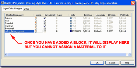
Back on the Display Properties (Railing Style Override - ...) dialog we can now take a look at the Layer/Color/Linetype tab to find that the Block has its own Display Component Name allowing you to set the Layer, Color, Linetype and other Properties. Unfortunately you cannot use the By Material Property and that creates quite a problem when you want to link the file to Viz Render. By the way, you will find this problem throughout ADT 4 including Multiview Blocks.
Material Tip:
Earlier I hinted at a work-around option for this little Material Problem. If you
create a custom Structural Member Style and set Material Properties as you want for the
custom insert, you can use it as the Block for the Insert and when you render it in Viz
you will get the cool materials. If you need to change the material, you can simply
edit the Style and you will be done; no need to redo the Block...cool huh.
Once you have one of these Custom Railing Styles down, you can swap the insert either by replacing the Block or by simply redefining the Block Name.