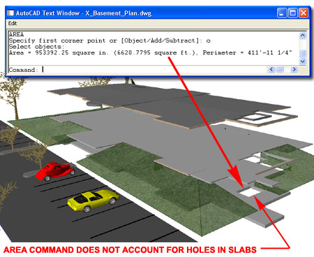
In the not to distant past I was under pressure to generate some rough estimates of floor areas on a multistory building I was working on and I made a whopper of a mistake. On many of my projects I don't bother with ADT's Spaces or Area Objects; I just go straight to Slabs with various Styles for Decks, Porches, Concrete Slab Floors, Wood Floors and so on. As an old AutoCAD user I often default to tricks learned many years ago and when I needed to collect some area calculations, I simply used the Area command and Selected Slab Objects. The problem with this technique is that the Area Command does not necessarily report the proper Area of ADT Objects and thus in this article I will discuss how to create your own Area Tag for Slabs.
Illustrated to the right I show that even if you don't have the Slab Property Data Set attached to a Slab, you can still get a reading of the Gross and Net Areas by using the List command.
In the steps below I will discuss how you can access the Slab Property Data Set that comes with the default installation of Architectural Desktop and attach it to any Slab. Not only will this allow you to use the Extended Data tab of the Properties Palette, illustrated lower right, to read the data but also allow you to tap into this data for things like Tags and Schedules.
By using the Style Manager (type AecStyleManager)
you can use the Open folder to access the "PropertySetDefs.dwg" file where
you will find a long list of default Property Data Set Definition Styles.
Chances are that you have already used many of these Sets because most are
automatically imported when you Tag Objects like Doors and Windows.
Since we don't have a Slab Tag you might not know that Property Data is so
easily accessible for this
 Object
Type. Once you have Copied the "SlabObjects" Property Data Set into any
active drawing file where you plan to take advantage of it, you will need to
attach it to a Slab Object in order to see any results.
Object
Type. Once you have Copied the "SlabObjects" Property Data Set into any
active drawing file where you plan to take advantage of it, you will need to
attach it to a Slab Object in order to see any results.
Illustrated to the left I show the default folder location for the PropertySetDefs.dwg. Custom Network installations may use a different folder location for this drawing file.
Illustrated to the right I show how the default SlabObjects Property Data Set offers automatic readouts of "Area-Gross" and "Area-Net" which are the primary subjects of this discussion.
Once a Property Data Set has been imported into a drawing file, attachment to Objects is not automatic. Illustrated to the right I show how you can use the "Add Property Sets" button on the Properties Palette to add or attach the "SlabObjects" Property Data Set to one or more Selected Slabs. This action can also be done at the Style Level to avoid having to do it after a Slab has been created. Once a Tag has been created, the attachment of the data can be a function of "tagging" and thus won't require that you do anything to the Slab Object or Style.
Attaching the SlabObject Property Data Set is a fairly painless and simple task but to really maximize the return on such an investment, having a Slab Tag that mines into that Data and presents data in the form of text would be awesome. Though Architectural Desktop offers a few Area related Tags, none are configured to work with Slab Objects and though you can tweak them to read Slab Objects, the results are often poor because Tags are usually best suited for the Objects they were designed for.
Illustrated to the right I show the basic overview of how you can create one or more Attributes (type AttDef) to tap into or mine for the data discussed above. The Property Set is named "SlabObjects" and there are two Area specific Data sources named "Area-Gross" and "Area-Net" respectively. By creating an Attribute Tag that combines the name of the Property Set with the specific data source, you can extract that information from the Object. Notice the use of the full colon ":" between the two names.
Note:
There is a neat feature within ADT Tags that can covert Attribute Text into
the current Text Style of any target drawing. This feature does not
work with regular text. To add suffixes and prefixes, users are
supposed to use Data Formatting Styles but in this example I decided to
avoid adding even more complexity by adding two more Attributes for the
prefixes "Gross:" and "Net:" Though I may never want to change these
terms, at least I avoid having to deal with the Data Format Style. If
I had used regular text, they would remain in the Text Style set here and
that reduces some of the flexibility of this Tag. You cannot set the Attribute
Mode to "Constant" in an effort to avoid making the attribute field
available for change at a later date and the reason is that when you use the
"Constant" Mode, the attribute Text Style does not change to match that of
the target drawing.
Read Area Tags for the full story on how to create Attributed Blocks for ADT Tags
By using the AEC Content Wizard later, I will set the scaling to "Annotation" which will use the "Annotation Plot Size" value as set on the Scale tab of the Drawing Setup dialog ( type "Units"). This means that the final height of my Attributes will be a factor of the current drawing scale and the Annotation scale. For example: drawing scale = 1:96, Annotation Scale = 3/32 so a Tag with text at a height of 1 will = 1*3/32*96 = 9.
After you have created your attributes and made a Block of them ( named mine "Aec3_Slab_Tag_P"), you will need to Add... this Block to a New MvBlock Definition as illustrated to the right. The reason for this action is to convert the Block into an ADT Object that will Anchor, Scale and Layer as other ADT Objects.
Illustrated to the right I show that I have created a New MvBlock Definition ( type MvBlock) that I have named "Aec3_Slab_Tag" to match the other Tags that come with ADT. For the General Display Representation I have Added my Attributed Block and set it's View Direction to Top only.
For the final stage of making your own custom Slab Tag, you will need to use the "Create AEC Conetent Wizard" (type "CreateContent") as illustrated to the right. The key to making a successful ADT Tag is to use the "Custom Command" Content Type option where you can add a Command String. The Command String is basically a series of command-line driven actions, like a macro, for how you want the Tag to be handled when inserted via the DesignCenter or Tool Palette. Be sure to Add>> the Attributed Block and the MvBlock at this stage.
Command String
The Command String is based on options you can type when inserting a Tag
into a drawing. You can type "AecAnnoScheduleTagAdd" to see the
options and test them before adding them as a Command String. Another
simple option is to Copy the Command String form a similar Tag, Paste it in
for your Slab Tag and simply change the name of the Tag. One option I
like to add to my Command String is missing from most of the default Tags is
the "Edit" "No" option because that prevents the Properties Palette from
popping up on your screen. Below is the Command String I use. Be
aware that there are spaces in the string to allow for keyboard returns.
_AecAnnoScheduleTagAdd PropertySetDefs.dwg _SYMBOL Aec3_Slab_Tag _LEADER _None _DIMSTYLE _Current _Edit _No
On the Insert Options page of the Create Aec Content Wizard you can set how you want your Tag to Scale, Layer, Rotate and what Text Style to use.
Once you have completed the work with the Wizard and exited the Tag drawing file, you should find a new Tag in the DesignCenter as illustrated to the right. Again, if I lost you on any of the steps for creating a custom tag, be sure to read the Area Tag article I wrote a while back.
Once you have a Tag that works properly from the DesignCenter, you can drag it over to any of your Palettes. Be aware, however, that if you need to edit the Tag, the best way to do that is through the DesignCenter where a simple right-click can either Open the Tag drawing File or allow you to Edit... the Aec Content Wizard settings.
Okay, I know that sometimes it's just a pain to go through all of the steps to learn something new when all you really want is the solution. You can download this Tag and add it to your Schedule Tags folder or use it to create your own version.
download >> Area Tag Slab Gross-Net.dwg