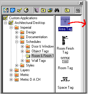
Recently, as I was working my way through all of the numerous Area and Area Group commands, I discovered yet another misleading reference in the Architectural Desktop User Guide that refers to adding Tags to Area objects. The problem is quite simple really, there are no Area Property Sets or Area Tags in ADT for Imperial or Metric use but there are a good number for Metric D A CH use. The problem is that many have never heard of this German standard nor do they have it loaded so we might as well learn how to create our own Area Tag.
As I see it, you have two paths to take and now I will offer a third based on one of these other ones - the option to simply download my solution from this article. But seriously, the two options you have are as follows: one, modify an existing Property Set and existing Tag ( such as the Space Tag or Area Tag from the Metric D A CH folder and make it work for Areas ) or two, create a Property Set and an Area Tag from Scratch.
Since we at ARCHIdigm are all about teaching, we'll discuss creating an Area Tag from Scratch.
Documentation > Schedule Data > Data Format Styles...
The first thing we have to do is define the way we want our Tag written; i.e. the format.
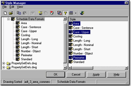
Using the Schedule Data Formats tool we can create, if required, unique Styles for each type of data.
Illustrated the the right, I show the three Schedule Data Formats that I will use in my example. The Area and Case - Upper Styles come from one of ADT's template files but the Perimeter Style is a custom one we'll make together. And since we are making it from scratch we will have to make sure it will be available in future drawings - we'll discuss this part later.
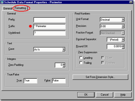
Illustrated to the right, I show the process of editing a newly created Schedule Data Format Style that I have called Perimeter.
On the Schedule Data Format Properties dialogue box, you can use the Format tab to control the output of text and numbers within tags. Since we need a way to denote that a certain numerical output is for the perimeter of an Area, we should probably state that it is a "Perimeter" measurement and that it is in inches ( " ). You can create your own solution for this scenario but basically all we really need to make sure of is that we put the quote mark or ".in" notation in so that the numbers can be read for what they are.
By comparison, if you look under the Area Schedule Data Format Style, you will see that it has a Suffix of SF (square feet). If you look under the Metric and Metric D A CH Schedule Data Format Styles, you will see "sqm" and "m". Keep this in mind if you want to start mixing tags from one Content folder with objects from another Content folder.
Documentation > Schedule Data > Property Set Definitions...
Once you have a Schedule Data Format for the output, we can move on to the next step of defining the output and this is done with Property Set Definitions.
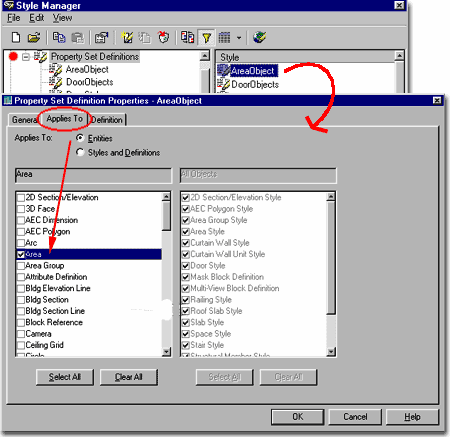
Illustrated to the right, I show that I have the Style Manager open filtered for Property Set Definitions and that I have created a New Property Set Definition Style that I have Named "AreaObject". You can call yours whatever you want but just make sure to remember the name.
By editing the New Property Set Definition Style, you can use the Applies To tab of the Property Set Definition Properties dialogue box to set what this new property will be assigned to.
Illustrated to the right, I show that I have set the Applies To: Entities radio button and checked the one entity that I want my new Property Set Definition assigned to: Area.
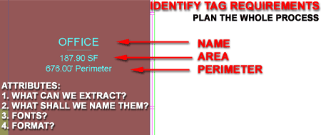
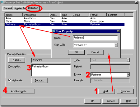
On the Definition tab of the Property Set Definition Properties dialogue box, illustrated to the right, I show that I have created three basic properties that I want to extract from my Area objects: Area, Name and Perimeter.
By using the Add... button you can quickly create New Properties that you can then assign a Format ( See Schedule Data Format discussion above ), Description and Source.
In the case of Area objects, we want to extract the information on the object's Area directly from the Source, so we need to use the Add Automatic... button to find an Automatic Property Source that holds the value or values we seek. These values are built into ADT for many of ADT's objects and thus the task should be rather easy - see cell directly below.
Once you have assigned a Source, the Automatic checkbox is automatically checked and you would only uncheck this to deactivate the Source.
In the case of this example exercise, we will assign Sources to each of the three Properties.
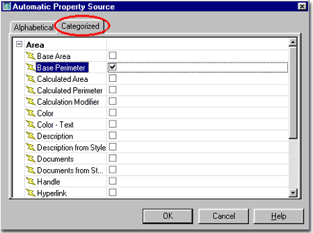
For each of the three Properties discussed above we will need to assign a Source from the Automatic Property Source dialogue box; illustrated to the right.
If you set the Applies To: Entities correctly on the Applies To tab, you should only see the Area Property Sources on this dialogue box.
Sometimes you have to use trial and error techniques to figure out which Source to use but eventually it will boil down to how you structure your Attributes. For this exercise, I used the following Sources:
Area => Base Area
Name => Name
Perimeter => Base Perimeter
Keep in mind that I am creating the most simple example here and you can easily argue for other methods but this one will work and work well.
This is a really important step to get right or you will have all sorts of puzzling error messages from the DesignCenter at the end of this exercise.
Because we created a custom Property Set Definition we have to add it to the master Property Set Definition Template file in ADT or this Property Set Definition will not be found upon insertion of our Area Tag symbol. In other words, you will associate a symbol to an object calling for properties that are not recognized by ADT. Since we also created a custom Data Format Style, we have the same problem with it but the good news is that we can stuff both Styles into the same file and be done.
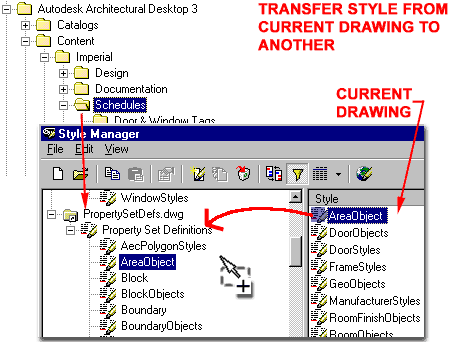
Illustrated to the right, I show that I have the Style Manager open filtered for Property Set Definitions. On the right pane in the Style Manager, I see my "AreaObject" Style. By using the Open button I have located the PropertyStyleDefs.dwg in Architectural Desktops Content folder -> [Drive Letter]:\ Program Files\ Architectural Desktop 3\ Content\ Imperial\ Schedules\ PropertySetDefs.dwg
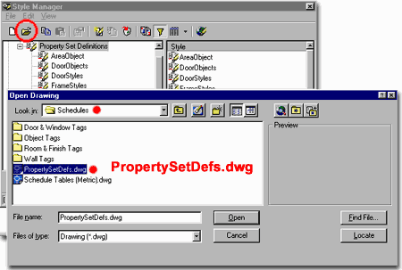
With the PropertySetDefs.dwg file Open and Expanded in the left pane of the Style Manager, I can drag-n-drop the AreaObject Style from the current drawing over. This process will make a Copy of it within the PropertySetDefs.dwg and preserve if for future use.
Repeat this process with the Schedule Data Format Style that we called "Perimeter" in this exercise and you will be set to move on. In other words, Copy the Schedule Data Format Style into the PropertySetDefs.dwg file.
Once you have done all of the database work as described above, you can focus on creating an Area Tag symbol.
By using the Attribute Definition ( "AttDef" ) dialogue box, we can set a Tag that will match the Style Name we used for the Property Set Definition and the Property Names we created within it. It is imperative that you use the Property Names exactly as you Named them on the Property Set Definition Properties dialogue box.
Illustrated to the right, I show that I have created a set of Attributes that look just like the Space Tag Attributes. You can, in fact, just reverse engineer the Space Tag to create this tag as illustrated by exploding it down to the raw attributes.
Since we have a lot of work ahead of us in the form of Blocking, Multi-View Blocking and AEC Content work, we need to get everything just right. With the AEC Content Wizard, we can set this attributed block to automatically scale to the drawing so we need to make it a small height - see illustration to the right.
I highly recommend creating this drawing in a blank AutoCAD/ADT file where the insertion point is at 0,0. Draw everything on Layer 0 (zero).
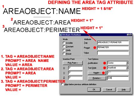
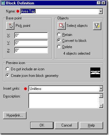
Once you have your Attributes Defined, we have to Block ( "Bmake" ) them as illustrated to the right.
Illustrated to the right, I show that I have Named my Attributes "Area Tag" and Selected them. Since I created my Attributes around the origin in such a way that the middle of the line is at 0,0 , I don't need to worry about a Base Point. For Insert Units, we will leave it Unitless so that it will scale incrementally.
Desktop > Multi-View Blocks > Add Multi-View Block...
Once you have a Block of your Attributes, as discussed above, we can move on to turning that Block into a Multi-View Block.
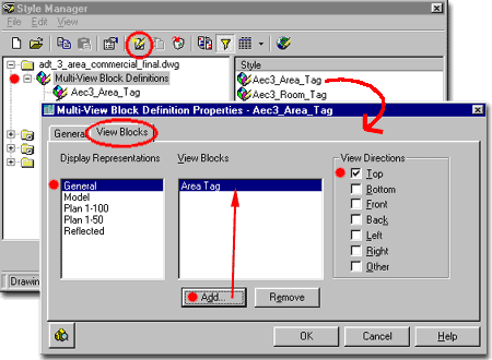
Illustrated to the right, I show that I have activated the Multi-View Block Style Manager and created a New MVBlock Named "Aec3_Area_Tag". You can name yours whatever you want but I chose a name that matched ADT's default nomenclature just to look more professional.
By editing this New MvBlock Style, we can use the View Blocks tab of the Multi-View Block Definition Properties dialogue box to set when our Tag will be displayed on the screen. Illustrated to the right, I show that I have used the Add... button to place the Area Tag Block, created earlier, into this Multi-View Block and then set the View Directions to Top. This means that it will not be seen when the drawing is viewed from the other directions.
At various stages along this process, it is probably a good idea to stop and test the work to make sure you have not made any mistakes. At this point, just before using the AEC Content Wizard, we should see if our Tag works and we can do that by typing the following command with the following specifications.
Command: AecAnnoScheduleTagAdd
Property set definitions drawing <C:\Program Files\Autodesk Architectural
Desktop 3\ Content\ Imperial\ Schedules\ PropertySetDefs.dwg>: <enter>
Select object to tag [Symbol/Leader/Dimstyle]: S
Enter tag symbol name <Aec3_Room_Tag>: Aec3_Area_Tag
Select object to tag [Symbol/Leader/Dimstyle]: <select your Area object>
Specify location of tag <Centered>: <pick a point to locate the tag>
Select object to tag [Symbol/Leader/Dimstyle]: <enter>
Command:
If it worked, then you are read to script this process via the AEC Content Wizard so you won't have to type it every time you want to use this Tag.
If it did not work, then you will have to
check all the steps thoroughly in reverse. Look for the obvious problems first
before the big things.
Did you type everything correctly?
Did you name your Multi-View Block something else.
Are you in the drawing file where this Multi-View block is defined?
Did you manage to Copy the Property Set Definitions over to the PropertySetDefs.dwg and is
that the file being loaded when you run the AecAnnoScheduleTagAdd command?
Desktop > Create AEC Content...
Now that such a huge amount of work has been accomplished, we might as well finish the job off as if it has been inside ADT all along.
By using the Create AEC Content Wizard, we can program the Multi-View Block we created earlier to behave more like the other Tags in ADT. If you read the command line carefully when you Drag-n-Drop the Space Tag into a Drawing and Anchor it to a Space object, you should notice a lot of commands and options have been used to achieve such a smooth process. By using the same steps, we can program them into our Multi-View Block so that it acts the same way when dragged from the DesignCenter. It is really just a Script of commands and they read as follows:
_AecAnnoScheduleTagAdd PropertySetDefs.dwg _SYMBOL Aec3_Area_Tag _LEADER None _DIMSTYLE Current
Notice that I have used the Multi-View Block Name that I created above: Aec3_Area_Tag. Obviously, if you used another name you better type it in correctly. Since it is so easy to make a mistake on the typing of this set of lines, you can Copy and Paste it off of this page but you will probably have better luck if you just Drag-n-Drop another Tag in, Hit the F2 Key and Copy that line from your history. Then, simply change the Symbol name.
Step 1 - Check the Custom Command radio button.
Step 2 - Use the Add... button to include the Block and Multi-View Block as part of the Content for this "Custom Command".
Step 3 - Use the Expand... button to open the Custom Command String dialogue box.
Step 4 - Add the String or Script provide above in large letters.
Step 5 - use the Next> button
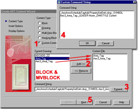
Note: notice that this script ( command string ) makes a call to the PropertySetDef.dwg file for the Style information we added earlier. You could use your own .dwg file for custom Style information if you wanted to.
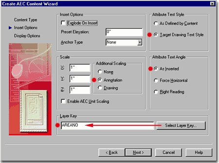
Set the Anchor Type to Tag.
Don't Scale anything manually but use the Annotation Scaling method instead so our Tag will read the text scale as specified on the Drawing Setup dialogue box.
For the Attribute Text Angle, set it to remain As Inserted unless you have other ideas about it.
And finally, let's use the Automatic Layering feature by using the Select Layer Key... button to assign a Key to our Tag: AREANO or equivalent.
Next>
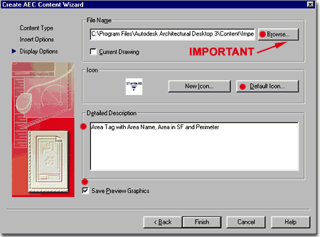
Use the Browse... button to visit your machine's Folder structure and look for a place inside Architectural Desktop's Content Folder to put this new Area Tag. The default place for an Imperial Tag would be: [Drive Letter:]\Program Files\Autodesk Architectural Desktop 3\Content\Imperial\Schedules\Room & Finish Tags.
Well, you could argue that it should go in the Object Tags folder or a New folder called Area Tags. No matter what, you will most likely want it under the Schedules folder.
If you followed my earlier instructions and did all of this work in a nice clean blank drawing file, then the only objects that should show up when you hit the Default Icon... button should be the Area Tag image. If not, you may have to use the Finish button, adjust your drawing and return to this point.
For the Detailed Description, you can type what you want in the DesignCenter Description Box when your Area Tag has been selected.
Save Preview Graphics is self-explanatory, isn't it.
Load the DesignCenter from the Documentation pull-down menu, Schedule Tags and the appropriate folder ( Room & Finish Tags, if you followed my logic).
Drag that Tag in and hook it to an Area object and see if it worked.
Don't tell me, it's not working...well, let's cheat then. If you have the Metric D A CH DesignCenter Folder, you can use the Area Tags from the Area Tags folder instead of doing all of this hard work. The only major problem for Imperial users is that the German Tags read as Metric even in drawings that have been set up for Inches and Feet. To fix this problem, simply go the to corresponding Schedule Data Format Styles and Edit the Prefixes and Suffixes as discussed above. Change the " sqm", for example, to " sq ft. " or equivalent.
Don't tell me, you are too tired to deal with it and you are ready to give up. Okay, I know how it goes sometimes, so here is the finished product. In order to make it possible to download and use without messing up your personal ADT files, I included a separate Property Set Definitions drawing called "ProperySetDefCustom.dwg".
The Zip file contains two files, one is the Area Tag which you can drop right into any of the Schedules folders ( Room & Finish Tags ) as you see them to the right; the other file is the PropertySetDefCustom.dwg file which you will need to put in the Schedules folder. In this folder you should see your own PropertySetDefs.dwg file that comes with ADT. By using this separate file, we won't rish corrupting yours.
Download: Area_tag_exercise.zip
