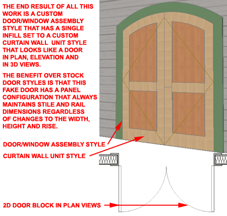
In the recently released Doors 9.0 eParts product I included a couple of doors under a section labeled "Experimental" that come as close to how I believe Doors should work in AutoCAD Architecture. I have categorized them as "Experimental" because they are highly customized and far from perfect.
One of the primary problems with Door Objects in AutoCAD Architecture is that the door panels are based on static Profiles. If you create a custom Door Style with a two-by-three panel configuration, for example, all of the dimensional values are scaled relative to the the original Profile dimensions. If you create a custom Profile where you want the stiles to be 5 1/2", for example, you will only get that true dimension when the Door Object is the same exact size as the Profile.
In my mind, a Door Panel should have been an independent sub-Object within a Door Style much like a Curtain Wall Unit is in a Curtain Wall or Door/Window Assembly Style. That line of thinking is what put me on the path to experimenting with Curtain Wall Units as Door Panels and this article will reveal what I came up with thus far.
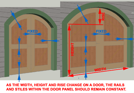
The first task in building a custom Door Panel that maintains fixed stile and rail dimensions regardless of the door size and/or rise change is to use the one Object in ACA that can produce this type of parametric functionality: the Curtain Wall Unit.
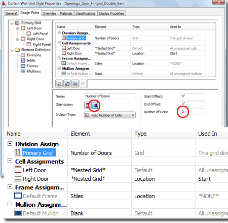
In the illustration to the right I show that I have created a new Curtain Wall Unit Style (type "CwUnitStyle") that I have named "Openings_Door_Hinged_Double_Barn". For the Primary Grid, I have renamed the default division to "Number of Doors", set the Orientation to Vertical and the Number of Cells to "2". The Division Type should be set to "Fixed Number of Cells".
Notice that I have added two "Nested Grids" under the Primary Cell Assignments; one named "Left Door" and the other named "Right Door".
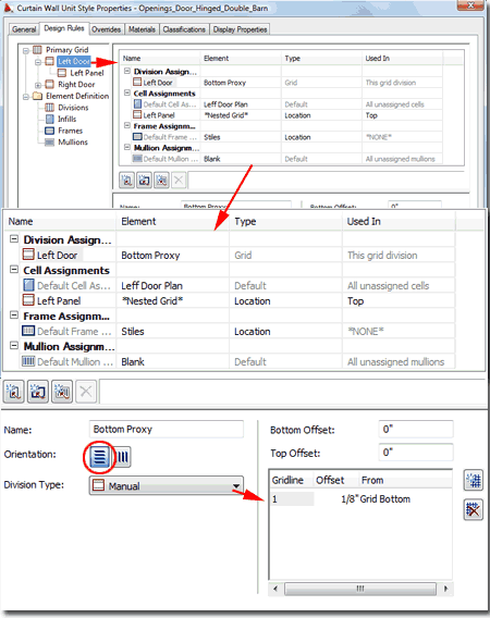
Through some trial and error experimentation I figured out a few tricks that will be needed to make a Curtain Wall Unit look like a Door. Some of the information illustrated to the right might appear like nonsense but was required.
In the illustration above I showed that I had created two Cell Assignments that were set to "Nested Grids" that I named "Left Door" and "Right Door". Illustrated to the right I show the "Left Door" Cell Assignment which is just another Grid. For the Left Door I created a New Division and named it "Bottom Proxy", set the Orientation to Horizontal, the Division Type to "Manual" and the Gridline Offset to 1/8" From "Grid Bottom". I realize this is weird but this is going to act as a placeholder for the 2D Door Display Representation and this will become apparent later.
For the Left Door I set the Default Cell Assignment to a new Infill that I named "Left Door Plan" with a Panel Thickness of 1 3/4". Then, I added another Cell Assignment that I set to "Nested Grid" to be Used In "Top" position.
The Grid isn't the Door Leaf itself but actually a way to divide the Door Leaf into a Top and Bottom where the Bottom will be used to show the 2D Plan of the Door while the Top will be the actual Door Leaf.
For Frame Assignments, I have set the Used In position to "*NONE*" because I don't want any frames around the bottom of the Door where I have the Proxy Infill. For the Mullion Assignments I created a New one that I named "Blank" with a Width and Depth of 0".
In the illustration above I showed that I added a new Cell Assignment that I named "Left Panel" and that I set it to "Nested Grid" for the "Top" Location. Illustrated to the right is how I configured this Cell Assignment as the actual Door Leaf.
For the Left Panel Division Assignment, I added a new Division that I named "Rails" with an Orientation set to Horizontal, a Division Type set to Manual and a Gridline set to 3'-0" From the Grid Bottom. This will split my Door Leaf into 2 parts divided by whatever I set as a Mullion.
For the Default Cell Assignments I added a New Infill that I named "Door Panels" with a Thickness of 1". This will act as the infill panel between the Rails and Stiles.
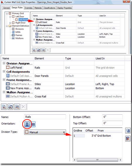
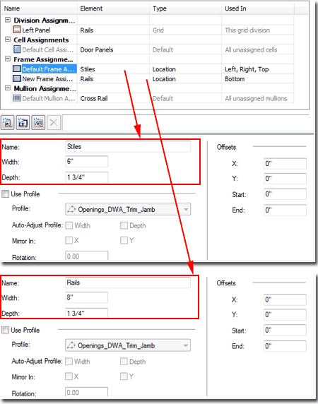
Continuing from the discussion above, I added two new Frame Assignments that I named "Stiles" and "Rails". I set the Stiles Location to "Left, Right and Top" and the Rails Location to "Bottom". The reason I set the "Stiles" to include "Top" is simply because I saw no reason to change the dimensions for the top rail; i.e., I wanted it the same as my stiles.
In the illustration to the right I show the Width and Depth dimensions I set for my Stiles and Rails. I designed my door to be 1 3/4" deep (or thick).
I also created a new Mullion Assignment that I named "Cross Rail" with a Width and Depth to match the dimensions of my Stiles.
Repeat these steps for the "Right Door" Cell Assignment. Everything is the same for the Right Door as the Left Door except the main Cell Assignment which should be set to a new Infill named "Right Door Plan". By having two different Infills within a tiny 1/8" space at the base of each door, you can assign a single 2D Block of a Door in Plan View to each.
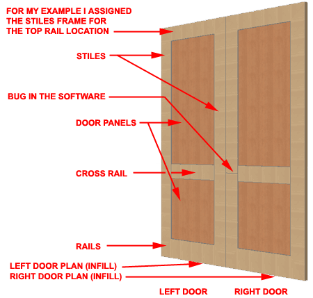
Illustrated to the right is what the work discussed above produces. You can draw a Curtain Wall Unit by typing "CwUnitAdd". The next step will be to create a 2D Door in Plan View, make a Block of it and Add it to the Plan Display Representation for this new Curtain Wall Unit Style.
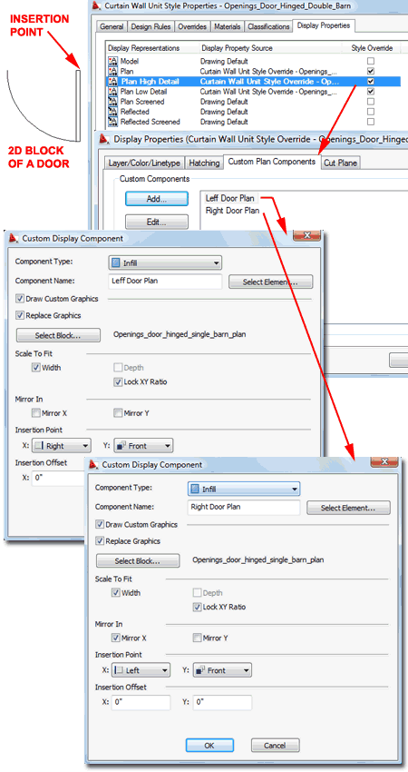
In the illustration to the right I show that I created a 2D drawing of a door in Plan View and made a Block of it that I named "Openings_door_hinged _single_barn_plan".
Back to the Curtain Wall Unit Style, I show that for Plan, Plan High Detail and Plan Low Detail Display Representations I have attached Style Overrides to add the 2D Door Block as a Custom Plan Component.
On the Custom Plan Components tab, use the Add... buttton to Add a Block. Set the Component Type to "Infill" and use the Select Element... button to pick the "Left Door Plan" Infill created earlier. This is the Infill that fills up that tiny bit of space at the bottom of each door leaf. It was necessary to use an Infill instead of a Frame because of how Frames are oriented in Plan View. Select the "Draw Custom Graphics" and "Replace Graphics" checkboxes. Use the Select Block... button to select the custom 2D Door Plan Block. Under Scale To Fit, use the Width and the "Lock XY Ratio" so the 2D Plan Block will always scale proportionately relative to the Width of the Infill in the CWU. Set the Insertion Point for X to "Right" and for Y to "Front". (note: the insertion points may differ for you if your Block was oriented differently).
Next, use the Add... button to repeat the steps for the right door panel. For this component, you will use the "Right Door Plan" Component and the "Mirror X" option. You will also need to set the Insertion Points for X to "Left" and Y to "Front".
In the discussion above I outlined how I created a fake door from a custom Curtain Wall Unit Style but that's only part of the story. Though you could use CWU's as standalone Objects, they were really designed to be nested within Curtain Wall Styles or Door/Window Assembly Styles.
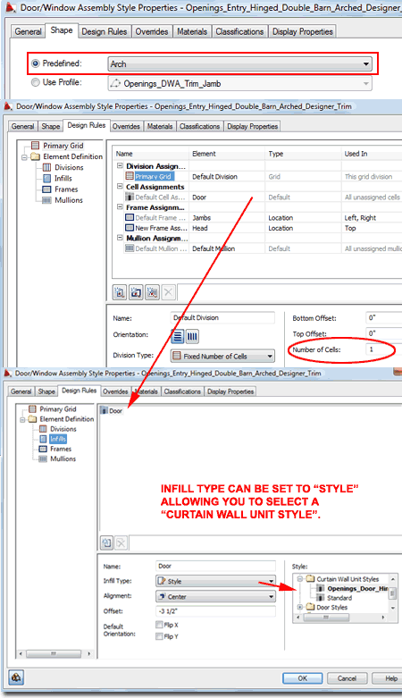
In the illustration to the right I show that I have created a new custom Door/Window Assembly Style that I have named "Openings_Entry_Hinged _Double_Barn_Arched_Designer_Trim". This DWA uses a Predefined Shape set to Arch which will demonstrate the flexibility of the CWU.
The Primary Grid uses the Default Division set to one Fixed Number of Cells. The Frame can be simple or fancy depending on your needs. In my example, which comes from the Doors 9.0 eParts product, I used custom Profiles for the Jambs and Head to create a trim effect. The most important setting in this DWA is the Cell Assignment, see below right, where I show that I have renamed the default Infill to "Door" and set the Infill Type to "Style". When "Style" has been set the "Style" scroll list offers access to the "Curtain Wall Unit Styles" folder in which I have the custom CWU I created earlier. For Alignment I used the Center option but in order to set the door at the corner of the jamb, I used an Offset value (-3 1/2") appropriate for the Frame Depth.
This is where the real magic occurs; when the CWU is assigned to the DWA it will conform to the shape and dimensions you apply to the DWA and the dimensions set for the stiles and rails will remain constant. To me, this is an awesome solution for designing custom arched doors.
Illustrated to the right is what all of the work discussed above should produce: a DWA with a CWU that looks like a pair of doors with stiles and rails that keep their original dimensional values.
