
3D Modeling in AutoCAD R14
Getting Started (Part 1 of
?)
Comments by: Odin Cary
Contents:
Setting up AutoCAD for 3D production work ---- Drawing
lines in 3D space ---- Making
2D objects 3D ---- Hiding, Shading and Rendering 3D objects ---- Creating
Basic 3D Surfaces
1Setting up AutoCAD for 3D production work
To follow the exercise as per
this page, you may download the following drawing file from the
ARCHIdigm site: Hol-deck.dwg.
Once you have downloaded this drawing file, move it to a project folder of your creation and open the file with AutoCAD.
1STEP:
The drawing you have just opened represents three axial planes (XY-plane, XZ-plane and YZ-plane) though two of these planes are not currently obvious due to the fact that we are looking directly down on to the XY-plane; also know as the World plane. Notice the icon in the lower left corner; the "W" stands for World plane. This icon is called the "User Coordinate System" icon or UCS.
Since our monitors are flat and 3D objects are not, we need to be able to see our 3D models from different angles simultaneously in order to visualize our models better in our minds.

To break your screen area up into "Tiled Viewports", select the View pull-down menu and go to Tiled Viewports. On this fly-out menu item, select Layout… and on the Tiled Viewport Layout dialogue box pick Four:Left.

2STEP:
 Now that the screen area has been divided
into four separate Viewports, we can set each one to display the
drawing from unique vantage points.
Pick on the middle left Viewport, anywhere inside of it, and make it active. Only one Viewport can be active at one time and usually the active Viewport has a bold or highlighted frame around it.

On the View pull-down menu select the 3D Viewpoint fly-out menu and pick on Front.
The middle left Viewport should now reveal a blue grid that is titled XZ-plane.
Pick on the lower left Viewport and make it active. Repeat the previous step by going to the View pull-down to 3D Viewpoints and then select Right.
The lower left Viewport should now reveal a yellow grid that is titled YZ-plane.
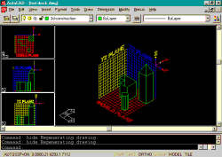
Pick on the main Viewport (Right) and make it active. Repeat the previous step by going to the View pull-down to 3D Viewports and then select SE Isometric.
 The end result should look like the image
to the right. Each Viewport can be adjusted with the Pan
and Zoom commands. I typically activate each Viewport
one-by-one and perform a Zoom Extents.
| Discussion: Notice the UCS icon in each Viewport. In the middle left and lower left Viewports, the icon is displayed as a broken pencil inside a square. This is done to indicate that the current vantage point in that particular Viewport is out of alignment with the current UCS setting. This is analogous to having a pencil perpendicular to a table while looking across the surface and directly at the wall behind the table. |
2Drawing
lines in 3D space
3STEP:
Make the main viewport (Right) active.
Set your Object Snaps to Intersection: Tools >> Object Snap Settings… >>Intersection
 Draw a several lines by selecting at
different point on the 3 uniquely colored grids and observe how
the lines look in the 3 left-hand Viewports.
Notice that the lines may look 2D in any single Viewport but may actually be in a unique plane of their own and not a part of the XY, XZ or YZ planes.
If you LIST one of these lines, you should see some new information as well as non-zero numbers in places where there are normally zeroes.
Example of LIST on a line drawn
across 3D space:
LINE Layer: 3D-CONSTRUCTION
Space: Model space
Handle = 66E
from point, X= 10.0000 Y= 1.0000 Z= 0.0000
to point, X= 11.0000 Y= 12.0000 Z= 7.0000
In Current UCS, Length = 11.0454, Angle in XY Plane = 85
3D Length = 13.0767, Angle from XY Plane = 32
Delta X = 1.0000, Delta Y = 11.0000, Delta Z = 7.0000
3Making 2D
objects 3D
4STEP:
Though our technological innovations are working towards a purely 3D modeling CAD environment, most of the work done today is 2D based. This means that a great deal of 3D work is derived from 2D drawings.
Erase the previous lines and set the main Viewport to Top: View >> 3D Viewpoint >> Top.
 Using Pline, draw on the Red Grid a
rectilinear form (like an imaginary building in plan view). On
another part of the Red Grid, draw a regular Circle.
Now reset the Viewport back to SE Isometric. This can be achieved by going through the pull-down menu, as described previously, or simply by performing a Zoom Previous.
To change these two objects so that they project into the Z-axis (or in other words, along the XZ and YZ planes), we need to provide them with a property called Thickness.
From the Modify pull-down select Properties
and then select both the circle and the polygon we just
created. If you find that the  objects are difficult to select, it is
probably because of the Red Grid. You can use Window or Crossing
to select with; the Red Grid is locked and will therefore not be
affected.
On the Properties dialogue box, notice the term "Thickness:" Type in a value of "5" (for 5 units of height).
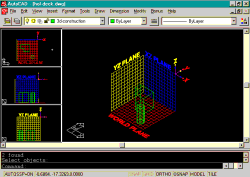
You have just created 3D objects.
4Hiding, Shading and Rendering 3D objects
5STEP:
Since AutoCAD is primarily a vector based CAD program, 3D objects are displayed as numerous lines in space and this is why the term "Wireframe" is used to describe how they are displayed. This should not be confused with what is called Wireframe construction, which suggests that the 3D objects are actually only made up of lines that represent edges. These objects, on your screen, are truly 3D and only displayed in Wireframe mode.
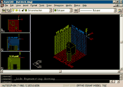
To see these objects as solids, AutoCAD has three separate commands to control 3D object display: Hide, Shade and Render.
From the View pull-down select Hide.
By activating each viewport, one-at-a-time, you can use Hide on all of them individually.
Notice that the cylinder appears solid or capped and the polygon appears hollow and the edges are paper thin.
From the View pull-down select Shade and 256Color. Try all four options: 256 Color, 256 Color Edge Highlight, 16 Color Hidden Line and 16 Color Filled.
Depending on your hardware, monitor and personal settings, you may experience unique results. 256 Color should produce a good image of a solid form with some edges darker than others.
From the View pull-down select Render and Render… On the Render dialogue box, the default settings should be appropriate for this example so simply pick on the Render button. The results may be impressive or poor depending on your hardware, monitor and personal settings but you should see the Grids disappear leaving only 3D objects and text. The 3D objects should look solid, smooth and dark on one side. Since we have not created a light source or a light intensity, the default values may not be very impressive. Rendering will be covered later in this series.
To reset the display back to normal Wireframe display, select Regen from the View pull-down menu.
 5Creating
Basic 3D Surfaces
6STEP:
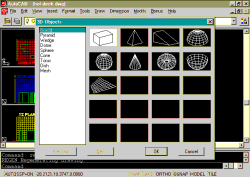
From the Draw pull-down menu select Surfaces and on the Surfaces fly-out menu select 3D Surfaces… On the 3D Surfaces dialogue box you will see several basic shapes and forms that you can create very easily.
Select Box3d and Snap
to an Intersection on the Red Grid. Make sure Osnap
is Off. Provide a Width of "3", a Length
of "3", a Height of "10"
and a Rotation angle about Z axis of "0".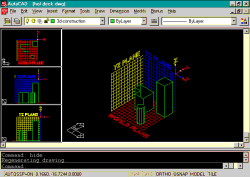
Note: If Osnap is on while typing points in space, like "10" for the height of our column, your cursor could catch a snap point on one of the 3 grids and create something quite different than expected.
Select Hide from the View pull-down menu and you should notice that the new 3D object has a top unlike the polygon object we created earlier.
| Discussion: This new object is actually constructed out of a new AutoCAD object type called Mesh. If you List this object or attempt to modify it with Properties you will notice its unique characteristics. If you explode this object, it will become 6 unique objects called 3D Faces. In this state, you can actually erase or uniquely stretch a single side. |
7STEP:
Now we will create a 3D Surface Pyramid.
From the Draw pull-down menu select Surfaces and on the Surfaces fly-out menu select 3D Surfaces…
 Select Pyramid and Type "0,0,0"
for the First base point: Move the Cross-hairs (the
cursor) towards the positive X-direction and Type "3".
Move the Cross-hairs towards the positive Y-direction and Type
"3". Move the Cross-hairs towards the negative
X-direction and Type "3". Now Type "1.5,1.5,3"
for the Ridge/Top/<Apex point>:
This creates a 3 unit square base pyramid 3 units high.
Use the Move command to move this Pyramid to the top of the column we create in Step 6. Remember that you are now working in 3D space and the only way to be certain about positions (points) in 3D space is to Type in coordinates or use Object Snaps.
=> Part 2