 eParts
for Architectural Desktop
2007/2008
eParts
for Architectural Desktop
2007/2008Cooking Appliances Installation Guide
IMPERIAL - RESIDENTIAL
Contents:
Greetings
---- Installing eParts ---- Using
eParts ----
Modifying eParts ----
Reporting Problems
|
|
 eParts
for Architectural Desktop
2007/2008 eParts
for Architectural Desktop
2007/2008Cooking Appliances Installation Guide IMPERIAL - RESIDENTIAL
Contents: |
| 1Greetings | .1-1 INSTALLATION GUIDE | ||||||||
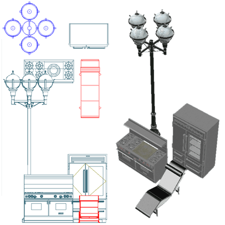
| Introduction Thank you for purchasing an ePart product from ARCHIdigm. eParts are comprised of collections of specific Object Types or Categories such as Refrigerators, Furniture and Street Lights. Many of these Objects come from our eKit products that offer a whole suite of tools for specific tasks such as creating kitchen or bathroom designs. Most eParts have been created as Multi-View Blocks (MvBlocks) consisting of Model, Plan and Mask components. Elevation Views are derived from the Model. Masks are for Plan use only and have been created by using a custom AecPolygon Style with a masking effect that can be turned on or off at any time. Some MvBlocks have a higher level of detail under the High Detail than the Low Detail. Some eParts, like Street Lights, have also been configured to repeat at intervals that you can control by working with the custom Curtain Wall Styles. |
 |
||||||||
| 2Installing eParts | 2-1 INSTALLATION GUIDE | ||||||||
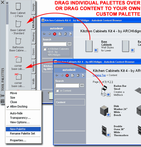
| For your convenience, this eParts product comes with a more elaborate installation option than some other eParts products. If you follow the installation instructions below, you will end up with a new Content Browser Catalog with a Cooking Appliances Palette that you can add to your current set of Palettes or just use straight out of the Content Browser. |
If you would rather just have the MvBlocks and add them according to your own methodology, you can extract them from this eParts Installation file. The main file in this eParts product is called "Cooking Appliances eParts.dwg". Read over the information below about how the .zip file has been assembled to find this file. You may also want to read the general eParts installation file. |
||||||||
Downloading and Unzipping the Files
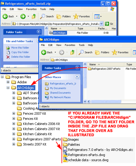
This kit was designed to be installed under the "C:\Program Files" folder and will not work properly if installed under other folders After installation, you should find that you have a New folder called "ARCHIdigm" and within this folder is the "Cooking Appliances 2007 eParts" folder containing all of the Style and Mvblock files that you will be able to access with your Content Browser. There is also an "Images" folder that contains all of the Tool Icons. |
|
||||||||
|
Downloading and Unzipping the Files -
Previous
Customer If you already have the "C:\Program Files\ARCHIdigm" folder for other eParts, eKits or our PowerSTRIP menu, simply double-click on the ARCHIdigm folder inside the .zip file to see the "Cooking Appliances 2007 eParts" folder. Drag this folder to the "C:\Program Files\ARCHIdigm". |
 |
||||||||
Add Catalog
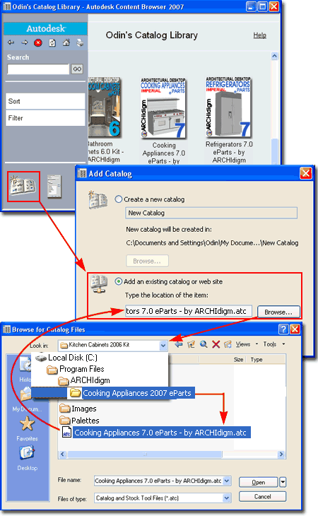
STEP 2: Once you have Opened the catalog file, you should find that you have a new Catalog Library with a Graphic Image that you can Select to access all of the Tools and Tool Palettes discussed below.
|
 |
||||||||
Add Tool
Palette and Tools
STEP 3: Tip: You can use the Ctrl+A keystroke technique to highlight all tool icons under a Catalog Palette or you can Select off in a corner and use the Selection Window to highlight a group. The Shift and Ctrl keys work to assist in Selecting items just as they do in Explorer. |
 |
||||||||
| 3Using eParts | 3-1 INSTALLATION GUIDE | ||||||||
| Adding
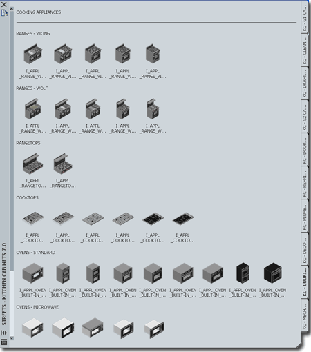
Ranges The Cooking Appliance Objects will insert as MvBlocks but many are actually far more complex and have the potential to offer true parametric features that will help users match most of the design options available for these products. |
 |
||||||||
|
Understanding how Curtain Walls are actually
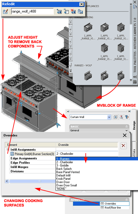
Ranges For ease of use, a variety of predefined Ranges and Cooktops have been configured as MvBlocks that key to the "Appl" Layer. They also come with Interference Blocks so you can subtract them from other Objects. Should you find that you would like a different configuration, you can Insert the Model Block and use Refedit to make changes which can then be saved back to the original MvBlock in the current drawing file. Illustrated to the right I show the MvBlock of a double oven range with the capacity for eight burners. I also show that I have Inserted the Model Block of the same range and activated Refedit in order to access the Curtain Wall Style that defines this range. For this example, you will see that it comes with all three back splash options available from this manufacturer but you can use the Height Grips and Osnap down to two, one or no back splash components. Burner, Griddle and Charbroiler options can be managed as Infill Assignment Overrides. On Ranges and Rangetops that already have Griddles and/or Charbroilers you should find that you can change these through the Overrides dialog on the Properties Palettes. |
 |
||||||||
|
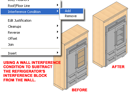
Subtracting Ranges from Walls or other Objects The MvBlocks in this eParts product contain Interference Blocks that can be used to Subtract holes in other ADT Objects like Walls. In the illustration to the right I show that I have used the "WallInterference" command to "Add" the Refrigerator as a "Subtractive" condition. Though there are other options for subtracting, this technique will allow you to move the Object and have the hole follow.
Note: |
 |
||||||||
| Style
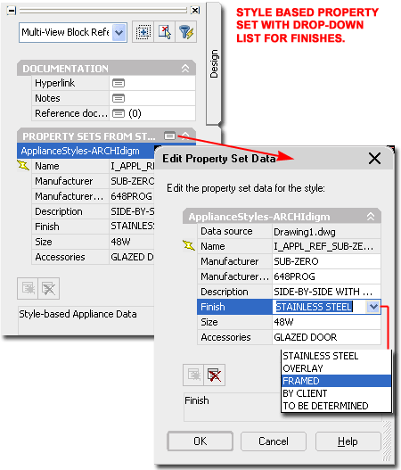
Based Property Set The MvBlocks in this eParts product have been populated with Style based Property Set Data that can be used to fill out a Schedule Table. Style based data is attached to the source Object and cannot be changed on the Properties Palette unless you use the "Edit Property Set Data" button which accesses the Style based Data. If you want to have two identical Objects with different Data, copy the MvBlock and provide a new name for this Copy. This will allow you to modify the Style based Property Data uniquely for the copy. In the illustration to the right I show that the Finish specification offers a drop-down list. This list has been set to allow input of other options than those in the list but you can modify the list by using the "ListDefinition" command and editing the "Appliance_Finishes-ARCHIdigm" Style. |
 |
||||||||
| Object Based
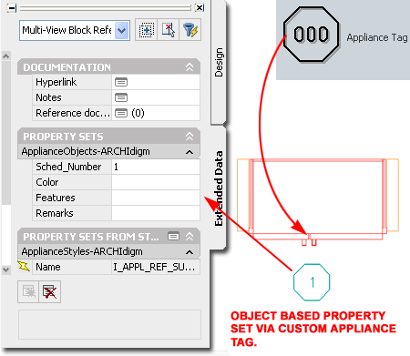
Property Set Included with this eParts product is a custom Tag that you can use to Number the MvBlocks and add Object based Data as illustrated to the right. If you want to modify the default Symbol
and/or Text, Open the "schedule data - source.dwg" file in the C:\Program Files\ARCHIdigm\Refrigerators 2007
eParts"
|
 |
||||||||
Template Files and Display Configurations
All ePart Objects have been optimized for work using the
Architectural Desktop 2007 "Aec model
Illustrated to the right is an example of how the three primary Display Representations, Low, Medium and High Detail, affect ePart Objects. Most ePart Objects include an AecPolygon Style set to Mask background information. This mask can be turned off if desired.
Low Detail
Medium Detail
High Detail
|
|
||||||||
| 4Modifying eParts | 4-1 INSTALLATION GUIDE | ||||||||
Muti-View
Block Anatomy
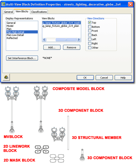
Most ePart Objects involve a complicated set of regular Blocks that have been assembled into a Multi-View Block. The complexity varies and may never be something you will have to think about but if you ever have a need to change one of these Objects, you will need to understand how they have been assembled. The most important thing that you need to understand about MvBlocks is that there is always a duplicate Block of the 3D Model Representation. By looking under the Model Display Representation on the Multi-View Block Definition Properties dialog, you can find the name of this matching 3D Model Block. By inserting this Block you can use Refedit to make changes to things like Material Assignments, Height, Width and so forth. Multi-View Blocks also provide the option to set different Blocks for Top (Plan) Views and these may even be different for Low, Medium and High Detail Display Representations. A feature of our eParts Objects is the use of custom AecPolygon Styles that act as Masks to hide Objects below. If these mask blocks produce undesirable results, you can turn off the masking feature - see comments below. |
 |
||||||||
Masks, AecPolygons and MvBlocks
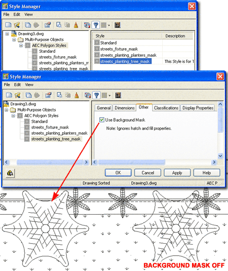
Most ePart Objects include a Masking Block as part of their structure. These Masking Block have been created by making a Block of an AecPolygon Object set to a custom Style where the "Use Background Mask" feature has been activated. By typing "AecPolygonStyle" on the command line, you should see a list of Styles with the word "mask" as suffix. By Editing any of these Styles and unchecking the "Use Background Mask" feature found under the "Other" tab you can remove the masking behavior - see illustration right. Mask Blocks may produce undesirable results when printing from Model Space due to the Black Background but this is not a problem when printing from Paper Space Layouts. The "DrawOrder" command can be used to move Mask Blocks up or down in the display stack. Note: |
 |
||||||||
Materials and
Mass Elements
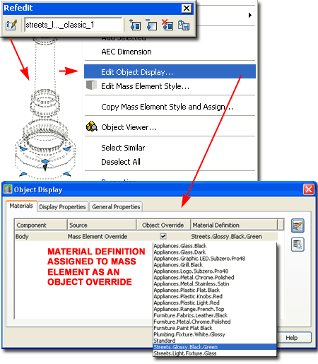
Most ePart Objects incorporate Mass Elements as a means of providing a 3D Model that will accept Material Definition Assignments. In other cases native Object Styles, such as Structural Members, Curtain Walls and Railings have been used whenever feasible and their Material Definition Assignments are managed by the Object Style. For Mass Elements, however, the Objects have typically been assigned to one custom Mass Element Style and Material Assignments set as Object Display Overrides. For Objects such as this, you can use the Refedit command to access the Edit Object Display... context menu option to change the Material Definition Override under the "Materials" tab - see illustration to the right. Keep in mind that an MvBlocks contains one or more regular Blocks so in order to access the actual 3D Model information you need to Insert the 3D Model Block, typically denoted by an "m" suffix. Once you have inserted the 3D Model Block, you can use the Refedit command to access the contents inside the Block in a way that will ripple back to the MvBlock once you save the changes. If you Open the eParts source file you will find that most of the 3D Model Blocks have been inserted for you so you can more easily identify them and even change them in this source file if you feel the need. |
 |
||||||||
| Materials - an
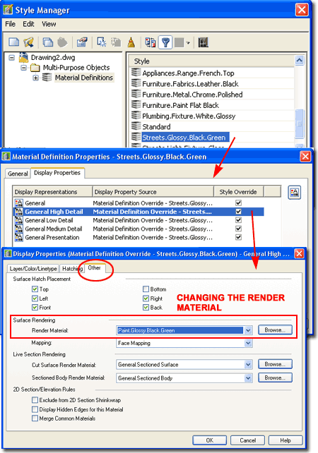
alternative approach to changing the Rendering Material If you are in a hurry and don't have the patience to change Material Definition Assignments remember that you can always change the Material Definition Style itself. For example, just because a Material Definition Style is named "Streets.Glossy.Black.Green" does not mean that you can't change the actual Rendering Material to a Glossy Red.
|
 |
||||||||
| 5Reporting Problems | 6-1 INSTALLATION GUIDE | ||||||||
|
Responding Let us know what you would like to see improved. |
|
© Copyright 2007 ARCHIdigm. All rights reserved.