| 1Automating
Sheet Layouts - Overview |
1-9 AUTOMATING SHEET LAYOUTS |
| The trouble
with getting sheets together At no point in
the history of AutoCAD has the problem of setting up sheets been addressed to my
satisfaction and that is why I have decided to include this part in the Deployment eGuide.
Since Architectural Desktop relies on AutoCAD tools for such tasks as Layouts, Page
Setups, Xref's and so forth, the problem is exactly the same. Generally speaking, in
any firm that regularly uses titleblocks, the process of getting the right sized
titleblock on a sheet and getting that sheet properly configured for any office printer or
plotter should be fully automated. In the discussion below, I outline all of the
steps we regularly employ to solve the whole sheet layout problem with the hope that you
can use it in your firm as well. |
 |
| The
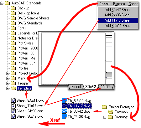
Assembly Structure Illustrated to the right
I show the various folders, files and custom menu that are all discussed in the Sections
below. To make the work easier to understand and complete, I have broken it into
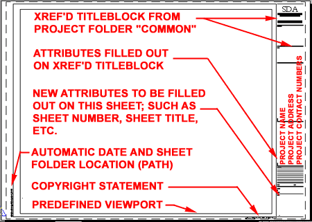
several phases. In the first phase, you will create a Standard Office Titleblock
with Attributes for the information that is common to a full set of Project Construction
Documents..
In the second phase, you will create a Standard Office
Sheet Template File where the Standard Office Titleblock is Xref'd into a Page Layout and
configured for printing. Attributes are added for the information that is unique for
each sheet of a full set of Project Construction Documents. This work is then saved
as a template (.dwt ) file.
In the third phase, you will create a Standard Office
Project Folder Structure with a "Common" folder to store the Project Specific
Titleblocks.
In the fourth phase, you will restructure the path of the
Standard Office Sheet Template File so it will always seek out a Project Specific
Titleblock once a user has saved the drawing file to a Project Folder ( Drawings ).
This work is then saved and the Template File(s) should be placed in the Template Folder
while the Titleblocks should be placed in the Common folder under the Project Prototype
Folder.
In the fifth and final phase, you will assemble a custom
pull-down menu using Lisp Code to enhance the ability to extract full Page Layouts from a
Template File. This will allow users to create Sheet Layouts in seconds. |
 |
| 2Creating
Standard Office Titleblocks |
2-9 AUTOMATING SHEET LAYOUTS |
| The
Titleblock
Given that this eGuide is written for CAD and IT managers,
I am not going to write out all of the steps for how to draw Lines, Plines, Rectangles and
so on in AutoCAD but hope that you know how to do these things. In many offices, a
lot of the work has already been completed so you may find that all you have to do is
reorganize and improve it. |
Calculate
the Margins:
To create a titleblock you will need to know
the standard sheet size(s) your office uses ( 24"x36, 30"x42" and so on )
and the physical printing limits of the printing or plotting device these sheets will be
printed to. Many printers have unexpected margin limits so be sure to calculate
these limits before drawing the titleblock border. There are basically two good ways
to figure out the marginal limits of plotters: one way is to see if they are listed in the
printer/plotter manual and the other way is to create a sheet with a series of horizontal
and vertical lines near the edges. By printing a sheet with lines near the edges,
you can calculate how far the printer/plotter will print before the lines disappear.
The Margin Lines that you should see on a Page Layout should also be a fairly good
indicator but some CAD and IT managers have chosen to set them to zero. |
Draw the
Borders and Titleblock Lines:
| Reminder |
Organize by Layers and
Colors for proper printing. |
Since the intent is to Xref this drawing into another
drawing file, a Template Drawing, you will want the linework to be in Model Space ( items
in PaperSpace ( Layouts ) cannot be Xref'd ). If you draw in a Layout configured for
the sheet, make sure to transfer the linework back to Model Space when done. Use 0,0
as the lower left corner of your border for best results but the insertion point can be
adjusted later during the Xref process so don't worry too much about this part.
Draw all of the items that will be static for all projects.
This includes lines inside the actual titleblock that represent divisions between
text, company logos, and so on.
Tip:
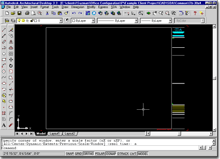
Adding Crop Marks at the exact paper size corners will contribute a lot to making the Plot
Area problem become nearly insignificant. In the illustration to the right, notice
that I have added four crop marks (red) in each corner. I have also assigned these
crop marks to a unique layer so they can be Frozen if desired. |
 |
Adding
Static Text and Attribute Text to the Titleblock
| Menu |
Draw> Block >
Attribute > Attribute Define... |
| |
|
| Keyboard |
AttDef |
| Links |
|
| Reminder |
Organize by Layers and
Colors for proper printing. |
| |
Be very careful about naming
Blocks; each name must be unique and that is why I use the sheet dimensions as part of the
name throughout this process. |
A well designed titleblock will contain two levels of
Attributes: one for the static part that remains the same for the entire project and a
separate Blocked part that is unique for every sheet. In this step we will add the
Attribute Text for the static portion.
Before you begin adding the Attribute Definitions, make
sure to create one or more Text Styles for the various parts of the
Titleblock.
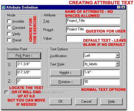
Use the Attribute Define dialog box to add
text to your titleblock. The Static Portion of a Titleblock will typically have such
items as, Client/Project Name, Address, Contact information and so on. There is
usually not a lot of information that needs to be added in this format to the Static
portion of the titleblock. Information such as your Company Name, Address and so on
do not need to be done with the Attribute Define dialog because they should not be
changing on a project-by-project basis.
Once you have completed the Attribute Definitions, they
must be turned into a Block in order for the text to become an actual Attribute. Use
the Block command to select all of the Attribute Definition objects (plus
anything else like Text Labels), Name the Block something like "30x42_Static_Tblock_Text"
and use an insertion point that will be easy to OSNAP to in the future ( something like
the lower left corner of the border ).
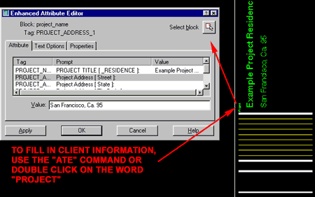
Insert the Attributed Block at the correct Insertion Point
( as established above ) and test the work by using the ATE command or by using a left
double-click on your mouse (see illustration below, right ). |
 Note:
If you leave all of the Value fields blank for the Attribute Definitions, make sure to
include some text or titleblock objects in the Block so users will have something to
select when wanting to edit the Attributes. In this example, I used a piece of
regular text for this purpose. The text I used was the actual title
"Project" but you can use "Client" or other similar labels ( see
illustration below ). |
| Saving the
Titleblock Since this titleblock will be
used as an Xref on every drawing for every project using this sheet size, the name will
have to be chosen with some care and consideration. If your office uses horizontal
sheet layouts for presentation purposes, you may want to differentiate the titleblock name
by something like "h" or "hor" for horizontal. Below I show a
list of names that I commonly use in architectural offices.
Tb_8.5x11.dwg
Tb_11x17.dwg
Tb_24x36.dwg
Tb_24x36_H.dwg
Tb_30x42.dwg
Tb_30x42_H.dwg |
 |
| 3Creating
Standard Office Page Setups |
3-9 AUTOMATING SHEET LAYOUTS |
| Creating
the Page Setup Template File To continue
with the Titleblock work started above, you will now have to create a New
Drawing File that will become a New Template File. You can use a blank
drawing file or start with a current template file that has other settings already
configured; such as those discussed in Part 7 and 8 of this eGuide.
Activate the first Layout, usually called Layout
1 and configure the page according to the needs of the titleblock you will be
Xref'ing in. In other words, if you are creating a 30x42 Sheet Layout, choose the
appropriate default plotter, pen table, sheet size, printing scale, etc., so users will
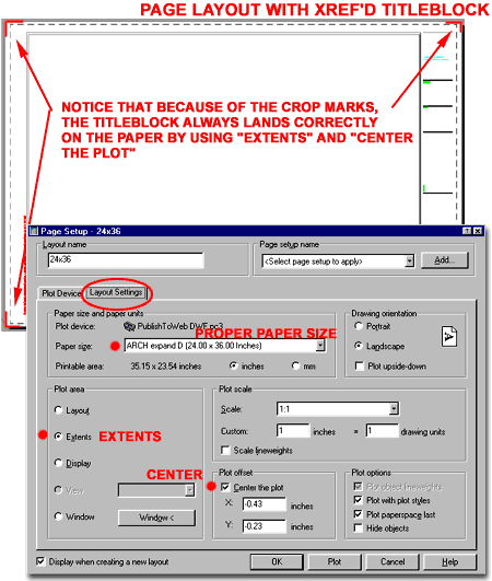
not have to think about these options when using this template file. For the Plot
Area, I recommend using the Extents option because this will
allow for Reductions without having to use the Window option later ( see dialog box below,
right).
Rename the Layout tab
to match the Titleblock Name; something like "30x42" |
|
Xref'ing a
Titleblock
| Menu |
Insert> External
Reference... |
| |
|
| Keyboard |
Xref |
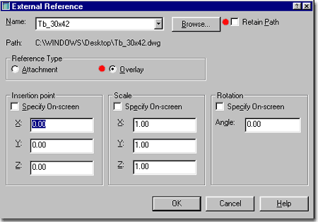
Use the Xref command to access the External
Reference dialog box and Overlay the Titleblock drawing file
created earlier ( Tb_30x42.dwg). Position the titleblock appropriately on the Layout
so it will be printed correctly and within the margins ( remember to leave room on the
left side for staples and bindings ). Don't Bother to Retain Path
because later we will reset the path so that it will automatically look to a project
folder instead of a single static location on a system of network server.
Tip:
A good trick for getting a titleblock such as this one into the exact position you want on
a Layout, is to create crop marks that sit relative to the border exactly as you want it
when printed. These crop marks should represent the exact size of the paper.
When Overlaying the Xref'd Titleblock with the crop marks, just drop the Xref anywhere on
the Layout. Now, use the Page Setup dialog box to center the paper to your Xref'd
titleblock by using the Extents Plot Area and the Center the Plot checkbox. If it
doesn't quite work the first time, try moving the Xref'd titleblock around a bit and make
sure there are no objects ( like Viewports ) outside the titleblock ( Extents ).
This technique has always done the trick for me even if I have to try it three times;
eventually it will match the paper to the crop marks. |
 |
Adding
Dynamic Attribute Text over the Xref'd Titleblock
| Links |
Adding Static Text and
Attribute Text to the Titleblock - for information on the Attribute Define dialog box. |
| Reminder |
Organize by Layers and
Colors for proper printing. |
| |
Be very careful about naming
Blocks; each name must be unique and that is why I use the sheet dimensions as part of the
name throughout this process. |
In order to provide the user with the ability to change
text on the titleblock for each sheet, we have to add Attributes over the Xref'd
Titleblock for the information that will be unique for every single sheet ( text like
Sheet Number, Date, Scale and so forth ).
Before you begin adding the Attribute Definitions, make
sure to create one or more Text Styles for the various parts of the
Titleblock.
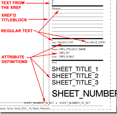
Use regular Text for the standard
Titleblock Labels such as "Revisions", "Scale", "Drawn By",
"Sheet" and so forth. These text items will be included in the Block of
Attribute Definitions but they will not be Attributes. What they are useful for,
however, is to allow the user to double-click on to access specific Attribute Fields for
faster editing.
Use the Attribute Define dialog box to add
Attribute Definitions adjacent to the Text Labels as illustrated to the right.
Once you have completed the Attribute Definitions, they
must be turned into a Block in order for the text to become an actual Attribute. Use
the Block command to select all of the Text and Attribute
Definition objects, Name the Block something like "30x42_Tblock_Text"
and use an insertion point that will be easy to OSNAP to in the future ( something like
the lower left corner of the border ).
Insert the Attributed Block at the correct Insertion Point
( as established above ) and test the work by using the ATE command or by using a left
double-click on your mouse. |
 |
| Saving
Sheet Template Files Once you are done with
all of the work described above, it is time to Save this As
a Template File ( .dwt ) that will be used over and over. This means that
the name should be chosen with care and thought. In addition to choosing a good
name, you will also want to consider a good location for this template file. I
typically add this template file to the Template folder that comes with
AutoCAD and Architectural Desktop. Earlier in this eGuide we discussed how this
folder was moved over to the Network Server so that would be a good location for this
template drawing file. |
To
personalize the template file for my clients, I name them with some reference to their
company or firm but in this example I will just use the word
"Sheet". If your office uses horizontal sheet layouts for
presentation purposes, you may want to differentiate the template names by something like
"h" or "hor" for horizontal. Below I show a list of template
names that I commonly use in offices.
Sheet_8.5x11.dwt
Sheet_11x17.dwt
Sheet_24x36.dwt
Sheet_24x36_H.dwt
Sheet_30x42.dwt
Sheet_30x42_H.dwt
When you save these template files, make sure
to use the Save As... option and set the Files of Type drop-down
list to AutoCAD Drawing Template File (*.dwt ). If you forget to do
this, just use Explorer and Rename the .dwg to .dwt. The only significant difference
with the renaming process is that you don't get to add a Description for users to read
when they select a template file. |
| Checking
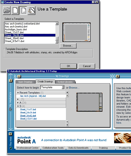
Sheet Template Files To check and confirm
that all of your hard work has been done correctly, you should now be able to use the New
option on the File pull-down menu in AutoCAD and Architectural Desktop
and be able to select the new Template File that was just created in the
steps above.
Depending upon how you set the Path statement on the Xref'd
Titleblock when we inserted it earlier, you may or may not see the titleblock. If
you do not see the titleblock and instead get that Xref path statement in the lower left
corner of the drawing, don't worry about it. This is actually exactly how the file
should behave at this point in the development cycle.
Save your current test drawing file to the same location as
that of your Titleblock and Reload the Xref'd titleblock. You should now see the
Titleblock.
Test all of the Dynamic Attributes to make sure they work
correctly and repair any mistakes by opening the original Template File.
In the next phase of this project, we will make sure that
the titleblock is always loaded correctly and that a unique titleblock is used for each
project. If we left things as they are now, the same titleblock would always be used
and that wouldn't work unless your firm always works for one client or under one project
title. |
 |
| 4Creating a Standard Office Titleblock Project Folder
Structure |
4-9 AUTOMATING SHEET LAYOUTS |
| Structure
for Automation To automate the insertion and
configuration of the titleblock and sheet setup for any project at any time, a new folder
will have to be added to every project folder where a copy of one or more titleblocks will
reside. These copied titleblocks are where users will add such information as
Client/Project Name, Address and so on ( the static information ). These copied
titleblocks also become a centralized link between all of the construction documents;
allowing for such things as a "For Review Only'" stamp across an entire set with
minimal effort.
If your office does not currently employ a folder system
for projects, you may have to begin a new trend. Many offices have very
sophisticated folder structures that they either copy from a template folder layout or
create by using software such as Columbus.
I typically name the Project Folder for
the titleblocks, "Common" but you can name it whatever you
think is most appropriate. If you do decide to use another name, just make sure that
you substitute your name for "Common" throughout the remainder of this guide.
The crucial element of this folder is that its position,
relative to all of the drawings that will use these titleblocks, remains constant.
To automate the insertion of the titleblocks, we will use a unique DOS based Path option
that will automatically look to the "Common" folder relative to a current
folder; and this will only work if the current folder location and the "Common"
folder location remain the same for all projects at all times.
Note:
For changes in file locations, users can use the Save Path option in the External
Reference dialog box to keep the titleblock link alive once a file has already been
created with the titleblock in place.
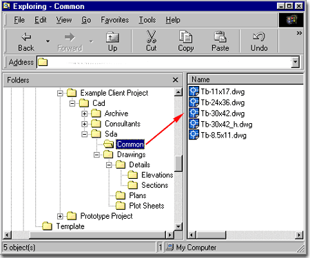
Illustrated to the right I show an example of a client
folder structure where the "Example Client Project" folder was created by
copying the "Prototype Project" folder structure. When
the Prototype Project folder structure is copied and Renamed for the current project, the Common
folder is also copied along with all of the standard office titleblocks.
When a project is started, a user simply opens one or all of these titleblocks and fills
in the static information. Or, this information can be filled in whenever it has
been made available to a project manager. |
 |
| Copying
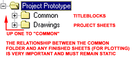
Titleblocks into the "Common" Folder To simulate and test the discussion above, create a Prototype Project
Folder Structure as outlined below or add a "Common" folder to any
project folder structure you currently use in your office.
Prototype Project
Common
Drawings
The location of this folder structure should, of course be
on a network server but it could also be tested and used on a local drive. Once you
have created the folder structure, copy the titleblock or titleblocks created as discussed
above into the "Common" folder and proceed to the next steps discussed below.
Note:
Though this example places the sheet files one folder below or away from the
"Common" folder, you do not have to limit yourself to this exact relationship.
The key is to understand that a static relationship must be established so a
non-specific drive path can be used to make the Xref's seek out the Project Specific
Titleblocks. See comments below for more. |
 |
| 5Automatic Xref Paths for Project Titleblocks |
5-9 AUTOMATING SHEET LAYOUTS |
| Repathing
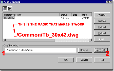
the Xref'd Titleblock in the Template File Open
the Sheet Template file ( "Sheet_30x42.dwt" ) created earlier
and use the Xref command to open the External Reference dialog box.
Highlight the Titleblock Name and on the Xref Found At path statement,
change the fixed drive and path location to the following:
"../Common/Tb_30x42.dwg".
If you did not name your titleblock
"Tb_30x42.dwg", then use the correct name and make sure that you use upper and
lower case letters where appropriate.
If you did not use the same Project Folder Structure, use
"../" for every folder you need to back up for in order to get to the
"Common" folder; i.e., "../../Common" for two folders up.
Once you have changed this path statement, the titleblock
will disappear because the path will not make any sense to AutoCAD or Architectural
Desktop until the file has been saved to a location where the path does make sense.
Save the Sheet Template file to the same
location and with the same name as is current. In other words, don't rename it and
don't save it to the Prototype Project folder. Save it back to the Template file
folder. |
 Note:
With some Operating Systems, an error message will occur when attempting to reset the Path
as discussed above. To remedy this problem, you will have to temporarily fool the
program into recognizing the path and this can be done by adding it to the Search Path
under the Files tab of the Options dialog box ( set it to Network Drive:\Prototype
Project\Common or whatever you decided to do for the steps outlined above ). Once
you have reset the path and saved the Template file, remove the path to the
"Common" folder so it won't be a permanent part of this customization ( this
would actually be a really bad thing because then the same titleblocks would show up for
all other projects ).
The other option you can use if you can't get
this trick path statement to work is to put the Sheet Template file in the Drawings Folder
of the Prototype Project Folder Structure so it will see the Common folder directly above
it. When done, just move the Sheet Template file to the Template directory. |
| Testing all
of the hard work If everything has been done
correctly, you should now be able to Start a New Drawing
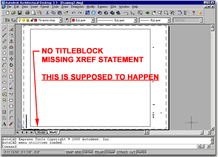
in AutoCAD or Architectural Desktop using the Sheet Template file. When it opens up,
you should not see any titleblock because the path has not been established. 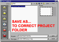 When you Save this drawing into
the \Prototype Project\Drawings folder, the path to the corresponding
"Common" folder should be established and you can either Reload
the drawing file or use the External Reference dialog box to Reload
the missing Xref'd Titleblock. When you Save this drawing into
the \Prototype Project\Drawings folder, the path to the corresponding
"Common" folder should be established and you can either Reload
the drawing file or use the External Reference dialog box to Reload
the missing Xref'd Titleblock.
Hopefully the logic of this whole structure has struck you
now. It means that any user can now start a new drawing file for any project and
will automatically get the corresponding titleblock as soon as they save their file to the
"Drawings" folder of any Project Folder Structure.
The next step is to allow a user to add Sheets with
Titleblocks to any current drawing without having to do anything other than select an
option from a menu. This will allow users to quickly add ready-to-plot Layouts in
seconds and save a lot of setup time. |
 |
| 6Creating a Custom Pull-down menu for Sheet Layouts |
6-9 AUTOMATING SHEET LAYOUTS |
Writing the
Menu
| Download |
Appendix - to download the titleblocks, template
files and this menu. |
In order to make the process of adding sheets to any
drawing file as easy as possible, it's best to provide your user base with a menu or
command sequence that they can use to run a set of routines that does all of the tedious
and difficult work. Since this eGuide is not intended to teach how to write custom
menus or how to write Lisp code, we'll simply use an example of a completed menu as a
teaching tool that you can adjust and customize to fit your own office needs.
Illustrated to the right I show an example Sheet Inserting
Menu and the Lisp programming code that I had to write in order to make the process of
adding a Layout work with the custom Xref'd titleblocks discussed above. Basically,
importing a full Layout from any other drawing is really easy but the problem is getting
an Xref to come through as an actual Xref. If you attempt to import a Layout with an
Xref in it, that Xref gets converted into a local Block and that won't work for the
structure we are creating here. What we must have is an Xref that looks to
the nearest ..\Common folder for the matching project titleblock so I added a few command
sequences that Attach the Xref and then remove it.
***MENUGROUP=Sheets - this is just the
name of the menu and you can name it anything you want but make sure that you also name
the menu file the same thing; i.e., this file is also called "Sheets.mnu"
***POP1 - this is just the nomenclature
used to indicate that this is the first pull-down menu in this custom menu.
ID_MNSheets [&Sheets] - this is the
name users will see at the top for the new pull-down menu. You can name this
anything you want without having to worry about any other names. The
"&" symbol indicates what letter will be underscored as per Microsoft menu
activation via the keyboard. If you want to change the name, only change the letters
inside the [ ] brackets.
ID_30x42TB [Add &30x42 Sheet]^C^C(setq
expert (getvar "EXPERT")) (setvar "EXPERT" 2) ( Setvar
"ATTREQ" 0 ) (command "._-xref" "o"
"../Common/Tb_30x42.dwg" "0,0" "1" "1"
"0") (command "erase" "l" "" ) (command
"layout" "t" "Sheet_30x42.dwt" "30x42" ) (setvar
"ATTREQ" 0 ) (setvar "expert" expert)
- this whole sequence is the name users get to select off
of the custom pull-down menu and what selecting this name actually does. The Lisp
code that follows the last ] bracket, deactivates some of AutoCAD's menu items so commands
can be executed without going through a dialog box interface. If you know just a
little bit about AutoCAD, the rest is pretty easy to understand because it's basically
just a series of commands that loads the Xref Titleblock we created earlier, Erases it and
then adds a Page Setup from the Sheet Template file we also created earlier.
In total, there are four example Sheets for this menu
illustrated to the right and each one uses a similar sequence of commands to import the
corresponding Page Setup and Xref'd titleblock from the closest "Common" folder.
You can literally Copy the text from the
right cell, paste it into a Notepad document, Save it as
"Sheets.mnu" and load it into AutoCAD to get a successful
custom menu running right now. Before you get too excited, let's go over a few other
items to ensure all of this will actually work for you. This menu is also already
available for you to download in the Appendix
of this eGuide so you may not have to do much work here.
Note:
If you did not use the same naming conventions as I outlined in this exercise, make sure
that you update the menu code to reflect any name changes that you made. The two
files referred to in the menu code is the Titleblock file (Tb_30x42.dwg)
and the Template file containing the Xref'd titleblock (Sheet_30x42.dwt). |
***MENUGROUP=Sheets
***POP1
ID_MNSheets [&Sheets]
ID_30x42TB [Add &30x42 Sheet]^C^C(setq expert (getvar
"EXPERT")) (setvar "EXPERT" 2) ( Setvar "ATTREQ" 0 )
(command "._-xref" "o" "../Common/Tb_30x42.dwg"
"0,0" "1" "1" "0") (command "erase"
"l" "" ) (command "layout" "t"
"Sheet_30x42.dwt" "30x42" ) (setvar "ATTREQ" 0 ) (setvar
"expert" expert)
ID_24x36TB [Add &24x36 Sheet]^C^C(setq expert (getvar
"EXPERT")) (setvar "EXPERT" 2) ( Setvar "ATTREQ" 0 )
(command "._-xref" "o" "../Common/Tb_24x36.dwg"
"0,0" "1" "1" "0") (command "erase"
"l" "" ) (command "layout" "t"
"Sheet_24x36.dwt" "24x36" ) (setvar "ATTREQ" 0 ) (setvar
"expert" expert)
ID_11x17TB [Add &11x17 Sheet]^C^C(setq expert (getvar
"EXPERT")) (setvar "EXPERT" 2) ( Setvar "ATTREQ" 0 )
(command "._-xref" "o" "../Common/Tb_11x17.dwg"
"0,0" "1" "1" "0") (command "erase"
"l" "" ) (command "layout" "t"
"Sheet_11x17.dwt" "11x17" ) (setvar "ATTREQ" 0 ) (setvar
"expert" expert)
ID_85X11TB [Add &8.5x11 Sheet]^C^C(setq expert (getvar
"EXPERT")) (setvar "EXPERT" 2) ( Setvar "ATTREQ" 0 )
(command "._-xref" "o" "../Common/Tb_8.5x11.dwg"
"0,0" "1" "1" "0") (command "erase"
"l" "" ) (command "layout" "t"
"Sheet_8.5x11.dwt" "8.5x11" ) (setvar "ATTREQ" 0 ) (setvar
"expert" expert) |
| Adding a
Custom Menu Folder to the Server
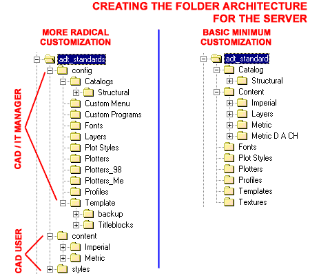
On the Network Server, under an
appropriate folder, create a new folder called something like "Custom
Menu" as illustrated to the right.
Go back to the previous step, above, and create the
new custom menu as per the instructions provided. You can also go to the Appendix and download the "Sheets.mnu"
file. Save the "Sheets.mnu" file to the
new "Custom Menu" folder that we just created
here.
|
 |
Adding the
Search Path for the Custom Menu
| Menu |
Tools> Options... |
| |
|
| Keyboard |
Options (OP) |
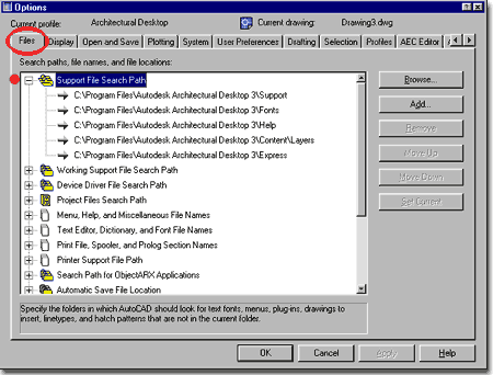
In AutoCAD or Architectural Desktop, use the Options
command to load the Options dialog box and Add a new Support
File Search Path under the Files tab: Use the Add...
button and then the Browse... button to create a Path to the "Custom
Menu" folder we just created. This will ensure that the menu will always be
read correctly. |
 |
Loading the
Custom Pull-down menu
| Menu |
Tools> Customize
> Menus... |
| |
|
| Keyboard |
MenuLoad |
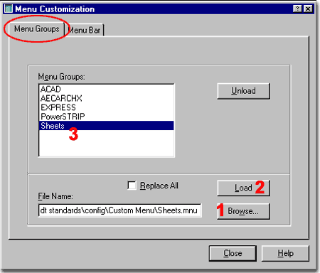
In AutoCAD or Architectural Desktop, use the MenuLoad
command to activate the Menu Customization dialog box. On the Menu
Groups tab, use the Browse... button to locate the "Sheets.mnu"
file you we just saved to the "Custom Menu" folder. Use
the Load button to import the menu. |
 |
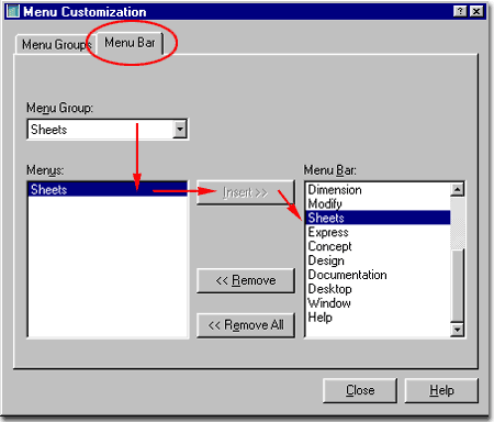
| Inserting
the Custom Pull-down menu into the Lineup The
menu should be compiled but you many not see it on the top along with the existing
pull-down menus. If you don't see the "Sheets" pull-down menu at the top
of your AutoCAD or Architectural Desktop, use the Menu Customization dialog box to add it
 Now, to test your pull-down menu, start a New drawing based on
any template file you want, even one of those "Start from Scratch" deals. Save
this file to the "Prototype Project >> Drawings" folder
so this drawing file resides one level below the "Common"
folder. Once you have saved the current drawing file to the "Drawings"
folder, you should be able to use the Add 30x42 Sheet menu option or any
of the others that you may have created in this exercise. Now, to test your pull-down menu, start a New drawing based on
any template file you want, even one of those "Start from Scratch" deals. Save
this file to the "Prototype Project >> Drawings" folder
so this drawing file resides one level below the "Common"
folder. Once you have saved the current drawing file to the "Drawings"
folder, you should be able to use the Add 30x42 Sheet menu option or any
of the others that you may have created in this exercise.
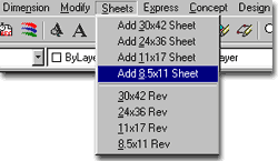
In the example menu illustrated to the left, I show that I
have also added some block insertion symbols for Revision Stamps on the titleblocks.
If you use the sample menu available in the download section of this eGuide, you
should find the same set of revision options. To make them work, you will need to
add the Revision Blocks to a folder that is on the Support Files Search Path.
Note:
If you get errors using the pull-down menu, chances are that you either have the folder
structure out of proper order, missing titleblock files or file names that don't match the
menu code. There really aren't that many places for something to go wrong, so just
run through these suggestions and look for typing mistakes ( that's usually the biggest
problem ). |
 |
| Testing all
of the hard work If everything has gone
well, this menu system, titleblock and project folder structure should all come together
to create amazing results in seconds. Illustrated to the right I show the Layout
tabs of a sample drawing in which several Sheets were added. |
 |
| |
|


 When you Save this drawing into
the \Prototype Project\Drawings folder, the path to the corresponding
"Common" folder should be established and you can either Reload
the drawing file or use the External Reference dialog box to Reload
the missing Xref'd Titleblock.


 Now, to test your pull-down menu, start a New drawing based on
any template file you want, even one of those "Start from Scratch" deals. Save
this file to the "Prototype Project >> Drawings" folder
so this drawing file resides one level below the "Common"
folder. Once you have saved the current drawing file to the "Drawings"
folder, you should be able to use the Add 30x42 Sheet menu option or any
of the others that you may have created in this exercise.
