If you haven't had a chance to tinker with AutoCAD 2005's Field Object, chances are that you have certainly heard about it. For me it is one of those new features that you get all excited about until you actually start digging into it and looking for ways to use it; you know what I mean?
On a fundamental level a Field simply offers the option to tap into AutoCAD's reservoir of drawing file data to extract and present that data as a text field. Users familiar with Diesel have been doing this type of extraction for many years now but it has never been quite as easy nor as expansive a task as it is today. You can, for example, extract something as broad as any of the drawing file properties (type "dwgprops" or as set externally by right-clicking on a drawing file) or something as specific as a Viewport Scale.
On a more sophisticated level a Field can be used to tap into specific data within other Drawing Files than the current one; a type of linked extraction. This is the realm where Fields become most valuable because it provides a tool for threading data to a linear source. In other words, consider for example, how often designers use callout bubbles to expand on information on another sheet at another scale and how often those numbers have to be correlated up until the very last day of a project. In a perfect world all those numbers would always be correct and this is where Fields offer a glimmer of hope. It's in the "threading" of the data that this part of Fields gets a bit weak and I'll expand on that below.
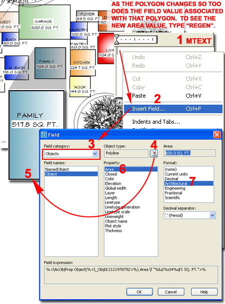
Illustrated to the right I show one example of the numerous Field Categories that you can access to tap into the current drawing file's data. One of the most interesting options is the Objects Field Category because it allows you to Select a specific Object and extract data from it; data such as the "Area".
Most Field values have a rather limited list of Formatting options that are generally tied to the Drawing File Units as illustrated to the right. In my opinion Fields should have their own Format settings independent from the Drawing Units and labels such as SQ. FT. should either be set as a Suffix of just separate text ( i.e., since Fields are Text we don't really need automatic Suffix statements).
There are
two primary variables that you may want to know about that affect Fields.
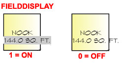 FieldDisplay
allows you to turn the gray box under Fields
On
or
Off. Though this gray box
does not print, I find it rather annoying when looking at a lot of Fields so
knowing how to toggle it On and Off is nice.
FieldDisplay
allows you to turn the gray box under Fields
On
or
Off. Though this gray box
does not print, I find it rather annoying when looking at a lot of Fields so
knowing how to toggle it On and Off is nice.
FieldEval
allows you to select one or more trigger actions for Updating; typically you
will find that you need to type "Re"
or "Rea" in order
to get Fields to update. There
are six options and you can choose multiples by using a bitcode value that
represents the sum of two or more. The default value is 31 which is
the sum of 1+2+4+8+16.
0 Not updated
1 Updated on open
2 Updated on save
4 Updated on plot
8 Updated on use of ETRANSMIT
16 Updated on regeneration
 Illustrated
to the left I show how you can use a Field,
Objects
Category, to Select a Viewport Frame and extract the "Custom
Scale"
Property. This Field will
monitor the Zoom Scale of the Viewport and always report the true scale.
To update the field after a change to the Viewport Scale, be sure to type
"Re" or "Rea".
Illustrated
to the left I show how you can use a Field,
Objects
Category, to Select a Viewport Frame and extract the "Custom
Scale"
Property. This Field will
monitor the Zoom Scale of the Viewport and always report the true scale.
To update the field after a change to the Viewport Scale, be sure to type
"Re" or "Rea".
Illustrated above I show how the Precision ( or number of zeros ) of the Area Property value of regular Polygons is controlled by the Drawing File's Drawing Units Setting. Unfortunately, I prefer to run a high Precision setting in my drawings to help track potential drafting errors but this reflects poorly in Area Fields. For Architectural Desktop users, it is interesting to note that not only are the Drawing Units important in controlling the output but using the Architectural Format for the Field itself causes erroneous output as illustrated above right with the Space Object. To remedy this error produced by reading the width and depth as feet and inches ( e.g., 50' becomes 50/12 = 4.166 and 50'x50' becomes 17.361 sq. ft. ), you can set the Field Format to Decimal and add the "Sq. Ft." manually to the Mtext statement.
As stated earlier, Fields can be used to tap into the current drawing's data but if you want to tap into another drawing's data, you'll need to invest in the Sheet Set Manager ( type "SSM") which is basically a subset of Architectural Desktop's Project Navigator. Thus far, the two primary cross-drawing or cross-sheet data tools are related to the Sheet Set and Sheet Views. Sheet Set data items that you can extract from other drawings ( or Sheets ) are limited and basically amount to Titles and Numbers which are rather useful to collate drawing indexes. Sheet View data items are similar to the Sheet Set data items but are based on Saved Views that are dragged into Sheets much like how many firms manage project detail sheets.
 Illustrated
to the right I show an example of how a Fields can tap into the data of
Saved
Views when processed correctly
through the Sheet Set Manager tool. In any drawing you can Save one or more Views. These views
can then be accessed via the Resource Drawings tab where they can be dragged
into a current Sheet Drawing File. Once the Sheet Set Manager has been
utilized to associate a Saved View with a Sheet, the View List
tab will allow
you to track and manage these linked Views and consequentially, new data is
available for a Field to tap into. At present the amount of data you
can tap into across drawings is rather limited and so are the tools in the
Sheet Set Manager for working with this data but it is an intriguing
beginning for a new era in the .dwg world.
Illustrated
to the right I show an example of how a Fields can tap into the data of
Saved
Views when processed correctly
through the Sheet Set Manager tool. In any drawing you can Save one or more Views. These views
can then be accessed via the Resource Drawings tab where they can be dragged
into a current Sheet Drawing File. Once the Sheet Set Manager has been
utilized to associate a Saved View with a Sheet, the View List
tab will allow
you to track and manage these linked Views and consequentially, new data is
available for a Field to tap into. At present the amount of data you
can tap into across drawings is rather limited and so are the tools in the
Sheet Set Manager for working with this data but it is an intriguing
beginning for a new era in the .dwg world.
Illustrated to the left I show how the Sheet Set Manager offers a few basic tools for managing Saved Views that are Linked to Sheets. Once a sheet has been set up with Details, for example, you can Rename and Renumber them ( this does not relocate them on the sheet of course ) and associate Detail Bubbles by using the Place Callout Block tool. Overall, the benefit of this extra work is to centralize reference data such as Detail Numbers and Sheet Numbers so changes don't have to be managed manually on all related callouts.
I think that it is rather clear that Fields offer the most powerful features when combined with the Sheet Set Manager or Architectural Desktop's Project Navigator but many offices are slow to adopt new procedures for managing project files and it would have been nice to see some cross-sheet data options without dependency on the Sheet Set Manager ( okay, maybe I'm asking for too much ).
If you are just getting acquainted with the Field Object in AutoCAD or Architectural Desktop, I recommend that you start using it in areas that have an obvious benefit and instant return on the investment in time and labor. A good example of this is on drawing Titleblocks for information such as the current drawing's filename, date and network location.
Fields can be treated as Smart Text Objects, be inside Blocks and Xref's or embedded inside Attributes. When you place a Field inside an Attribute, it allows a user to override the Field's default function. An example of this is the sheet date on a drawing where the Field might always report the actual date but you decide that you need to freeze it to a fixed date.