Over the last couple of years I have received numerous questions about creating log walls in Architectural Desktop and I have done my best to evade the subject as much as possible. I frankly don't believe that Architectural Desktop offers a good solution for this type of work(which is just one part of the larger timber framing subject) but, like AutoCAD users, ADT users will shove an elephant through a keyhole.
Whenever I am faced with new and challenging problems in ADT I typically ask myself whether it is an aesthetic effect that I seek or a true mathematical solution. In addition to this pondering over this question I try to assess the effort (time) involved in any of my options so I can maximize my path to Construction Documents, Permits and so forth. In this discussion I have decided that the value of working with ADT's native Walls outweighs most other options but you may have a different opinion. My solution, therefore, is primarily based upon an aesthetic effect.
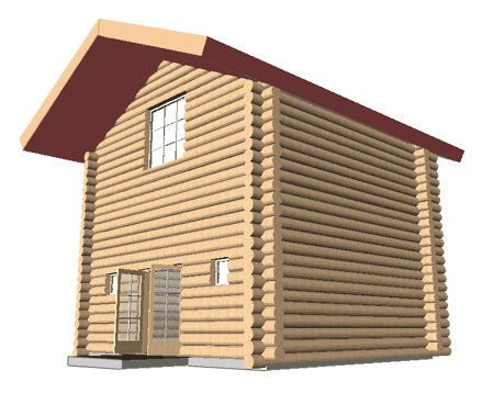
To prepare for a log wall solution in ADT you should start by creating a new custom Wall Style and you may find that you will eventually need several versions of this Log Wall Style for different construction techniques or conditions. Because the details of creating custom Wall Styles is a whole story in itself, I am not going to elaborate on how to make your own Wall Style (you should know that by now if you are planning on taking this type of a task on). To save time I will create my two example Log Wall Styles by Copying existing Wall Styles from ADT's Library, Rename them and make whatever basic modifications I think are necessary.
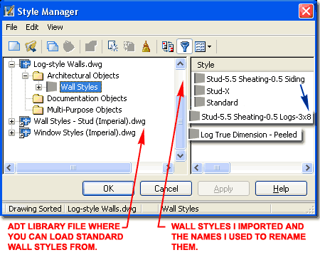
Illustrated to the right I show how I have used the Style Manager (type "WallStyle") to locate the "Wall Styles - Stud(Imperial).dwg" library file and Imported the "Stud-5.5 Sheating-0.5 Siding" and "Stud-X" Wall Styles. By the way, I believe "Sheating" should be "Sheathing". You can also import these Wall Styles by means of the Content Browser.
After importing these Wall Styles, notice that I renamed them to avoid confusion and potential overriding. For one of my examples I am simply going to replace a common Wall Component, the Siding, with a 3"x8" half Logs so I have renamed the word "Siding" as "Logs-3x8". For the other example, I am going to turn the single Wall Component into a true log; hence the name "Log True Dimension - Peeled".
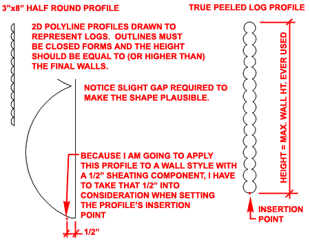
 In
Plan (Top) View draw a sectional representation of your Log Wall Style as
illustrated to the right. For the example where the logs are actually
a type of siding, I show that I have drawn half-round shapes but provided a
slight gap of distance from the straight edge line at the back in order to
avoid problems later on.
The shape you create must be a full closed form and thus this limits options for height control later on. In my two examples to the right I show that I have drawn one log profile to a plate height of 8'-0" which is how I expect to apply it to my Walls. For the other log profile, I have drawn it well beyond a normal plate height but that will provide more flexibility later on.
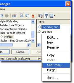
Once you have created your Closed Polyline log profiles, use the "ProfileDefine" command to activate the Style Manager. Create a Profile Name as illustrated to the left and use the Context menu to Select the "Set From..." menu option ( you can also access this option from one of the buttons on the Style Manager). After Selecting your Polyline shape, pass the option to "Add another Ring" and stop at the request for "Insertion Point or <Centroid>:" The Insertion Point for Profiles that will be used as Sweeps on Walls should never be the default of "Centroid" so you will need to pick a specific point on the Polyline shape. In the illustrations to the right I provide some information to help with this subject but ultimately you may need to resolve this with some trial and error passes.
When creating a half-log Polyline Profile, you may find that once you Sweep it along your Wall, it becomes inverted. To remedy this problem, Mirror the original Polyline shape and run through the steps of defining it as a Profile once again.
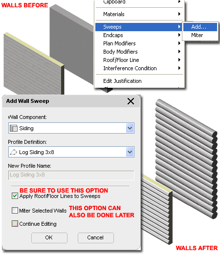
To test the new Log Profiles as Sweeps on your custom Wall Style(s), draw a section of Wall as illustrated to the right. Select a Wall, right click and Select the Sweeps > Add... Context menu option.
On the Add Wall Sweep dialog, be sure to specify the correct Wall Component that you wish to reshape. Be sure to specify the correct "Profile Definition". Of the three checkbox options at the bottom of this dialog, I recommend that you always set the "Apply Roof/Floor Lines to Sweeps" to allow for Height changes later on (see discussion below). You probably will not want to Miter your Log Walls but if you do you can set that option here or use the "WallSweepMiterAngles" command later.
Note:
A Sweep is a Profile that follows the length of a Wall much like the Extrude
command creates a Solid by following a Path. You can create all of you
Walls and run Sweeps on them later or you can run a Sweep on one Wall and
use the "Add Selected" Context menu to draw new ones with the same Sweep.
You cannot store a Log Wall Style as you would expect because the Sweep is
not a Style Property. This means that you cannot make a button on the
Properties Palette unless you make one that Inserts a full sample of the Log
Wall. Once you have a Log Wall sample in drawing, even by Copy and
Paste, you can use it to create new Walls.
One of the most frustrating things about using Sweeps is how limiting they are once applied to Walls. When it comes to Log Walls, the simple task of making them Higher or Lower can be exasperating and you may want to avoid applying the Sweep until a later time in the design or CD phase to avoid spouting out expletives.
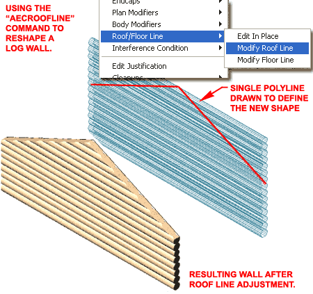
Illustrated to the right I show how I have managed to reshape the Log Wall whose Profile I intentionally drew well beyond normal plate heights. To shorten or reshape the top of a Wall, all you have to do is draw a single contiguous Polyline (even a single straight one) at the proper Z-axis height relative to your Wall and then use it as a tool to "Project" to.
You will find that you can access the "Modify Roof Line" or "Modify Floor Line" command via the Context menu as illustrated to the right. You should also know that you can type "RoofLine" or "FloorLine" as commands. In addition, both command offer command-line options that you may need to use for better results. I find "Project to Polyline" one of the more successful options. Look to the Worksheets section of the Properties Palette to access Roof/Floor Line changes.
Note:
You will not be able to use this option to make a Sweep higher than the
original height but you can use it to reduce the height. I find that
the Floor Line option tends to produce undesirable results with log Sweeps
but you may get better results.
 I'll
start this example with a statement about Log Wall Corners: I hate them!
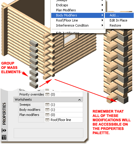
Illustrated to the right is a clumsy approach to solving the look of overlapping log corners but I show it because I did it and it will provide you with information about using Body Modifiers - I think these are very useful.
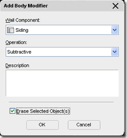
To remove a portion of my example Log Wall, illustrated to the right, I created a series of Mass Elements and placed them along one Wall. I kept a copy of this work for other Walls. By executing the Body Modifier > Add... Context menu option, I Selected the Mass Element Group and applied them as a Subtractive Operation on the "Siding" Component of my example Log Wall. On the Add Body Modifier dialog I also used the "Erase Selected Objec(s)" check box because I will not need the Mass Element Group after my work is done.
The biggest problem with this solution is that Body Modifiers are a pain to deal with when you want to modify a Wall. When you lengthen or shorten a Wall, for example, the Modifier can appear to move due to its fixed position relative the the Wall's original Start point. If you use an Interference Condition instead, you can move the Subtracting Body but then you'll have to track it on some non-printing layer. Read comments below for another option.
If you use Architectural Desktop for Log Walls and you need even more control and flexibility, particularly at the ends, you may want to explore the process of creating a Wall Style with one component for each Log. This would mean that the Profile you Sweep would need to be a single Log End repeated for each Log Component. However, once complete, you would be able to create a series of Wall Endcap Styles that would allow you to cut each Log End uniquely.