I was in a terrible hurry the other day trying to provide a series of design options for an addition on a very cramped lot when I ran into a little ditty of a problem. One option called for an angled wall that matched the adjacent property line. Everything was quite easy to model in ACA 2009 until I got to the roof which was easy to visualize in my mind but not quite so easy to model.
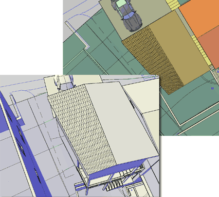
In the illustration to the right I show the completed roof to help explain what I am talking about here. The roof, on one side, is cut at an angle to match the walls below. The ridge and fascia remain constant but the two gable ends have different slopes. AutoCAD Architecture's Roofs and Roof Slabs don't allow for this type of slope variation.

Whenever I am pressed for time I run through my memory banks for ideas that may appear obsolete and that line of thinking led me to Surface Modeling.
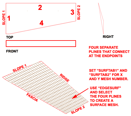
In the illustration to the right I show how I created 4 separate Polylines to represent the edges of the roof I wanted. The Polylines labeled as 2 and 4 were drawn in plan but the other two were drawn in an Isometric View so the proper slope could be accounted for. In order for this technique to work, each Polyline end must connect perfectly with the other two.
To turn the Polylines into a surface mesh, first set "Surftab1" and Surftab2". These variables store the number of tessellation lines to be used in the surface mesh. Surftab1 affects the first Polyline selected. Polylines must be selected in an order of adjacency; i.e., selecting opposite sides won't work.

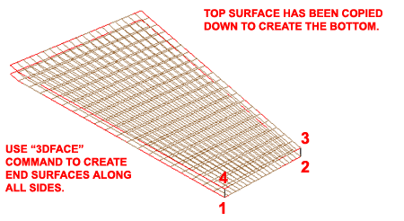
In the illustration to the right I show that I have copied the surface created above down an distance equal the the thickness of my roof. Then, I show that I have used the "3dFace" command to fill in the missing faces or surfaces along the four sides. If the form was even more complicated, the sides could also be created using the EdgeSurf command.

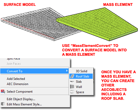
In the illustration to the right I show that I used the "MassElementConvert" command to convert the surface model into a Mass Element.
Once you have a Mass Element, you can Convert it to other AecObjects like a Roof Slab.
I was not able to find a way to remove or even reduce the faceting created from the original surface form. The really unfortunate aspect of this is that those facets show up on Plan Views and this is not something you want in a Roof Plan. However, you may want to keep this trick in mind as you encounter tricky problems similar to this one or when you find surface models (like those from websites) that you want to convert into Mass Elements.

In AutoCAD 2009 and verticals, even with SP1, you cannot OSNAP to anything on a 3D Mesh such as the one discussed in this article.