Architectural Desktop continues to fall short in the framing department but that has not stopped me from looking for tricks. For the most part I really don't need a full-blown framing tool that can show me all of the studs used to frame my walls but there are times when framing is something I really need to show in Sections, Elevations and 3D Renderings.
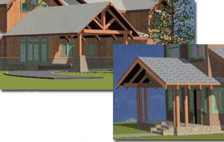
On a couple of projects I recently completed, the designs called for exposed roof rafters and because I was short on time I had to concoct a solution that would only take a few minutes to assemble. These days whenever I am faced with the need to create repetitive Objects in ADT I include Dynamic Blocks as one of the tools at my disposal. In the discussion below I will outline the steps I took to create the results I show to the right.
When it comes to creating a Rafter, Truss or other ceiling framing solution you are likely to find a variety of solutions offered by anyone who has taken a stab at this problem in ADT. In the illustration to the right I show one of my favorite tricks for creating a simple pitched Rafter Span. I like this solution because it is based on the same solution I typically apply to creating the primary roof massing form; i.e., I get to use the same tool for pitch, overhang, edge cut and so on. If you prefer other options like using Structural Members or Curtain Walls, those will work too.
 In
the illustration to the right I show that I used the Roof (RoofAdd)
tool to create a very narrow roof. The width, between point 1 and
point 2, is actually the width of the rafter. The length should be set
to match the span of your building and the two overhangs should match what
you expect to use as well. To turn the odd hip roof into a rafter I
changed the Slope and Overhang Value of the sides to
90d and 0" respectively.
In
the illustration to the right I show that I used the Roof (RoofAdd)
tool to create a very narrow roof. The width, between point 1 and
point 2, is actually the width of the rafter. The length should be set
to match the span of your building and the two overhangs should match what
you expect to use as well. To turn the odd hip roof into a rafter I
changed the Slope and Overhang Value of the sides to
90d and 0" respectively.
Before you create a Block of the completed Rafter, you may want to jump down to the next cell and change the Display Properties.
When you create your Block of the Rafter, consider how you want to place the first Rafter relative to your Walls or Roof. In this example I show that I will use the outside edge of the Rafter ridge as my Base Point and the reason will become more obvious later.
On the Block Definition dialog, be sure to check the "Open in block editor" checkbox so you automatically jump to the Dynamic Block Editor.
If you use a Roof Object, as I am in this example, remember that these Object types do not have Styles. This means that you will need to use the "ObjectDisplay" command to set the Material and any Display Overrides. You can make Display changes before or after you have defined the Block.
Illustrated to the right I show that I have set a Wood Material Definition for my Rafter and set numerous Display Representation Overrides. For each Display Override, I set the Visibility of the Eave Display Component to Off. This will prevent undesirable dashed lines that typically represent the Eave on Roofs with Overhangs.
In the Dynamic Block Editor, Copy the 1st Rafter and place it as far away as you would normally place your Fascia Board. Copy the 1st Rafter in the opposite direction and place it as far away as you would for your normal framing spacing (like 24"). Copy this Last Rafter and place it as far away as you did for the Fascia Board on the opposite side. You can change the Width of the Fascia Boards if you need to.
When you are creating this type of framing tool, the first thing on your mind is likely the spacing between each rafter so I will address that first and then move on to the Fascia Boards below.
To configure the 1st Rafter so that it will Array according to your Grip Stretching, use the Linear Parameter to set two points as illustrated to the right. If you find it difficult to Osnap to 3D Objects, go ahead and draw some regular Lines to set points. Because I only want one Grip for my Rafter Stretch, I have to draw the Linear Parameter so that the 2nd Point is the last one. Also, because I am going to use the Array Action, I will need to set the distance for the Linear Parameter (labeled "Rafter Spacing") to twice (2x) the spacing I want for my Rafters. Though this may sound illogical, it has to do with how the last Rafter and 2nd to last Rafter are placed.
For the 2nd Point of my Linear Parameter I have Osnapped to the outside edge of my Last Rafter to match how I set the Insertion Base Point for the 1st Rafter. Once you have your Linear Parameter set, you can Rename it and set the Number of Grips value to 1.
To get the Array Action to work, Select the Linear Parameter and then the 1st Rafter. Don't worry about any of the other Rafters because those will be addressed later. On the Properties Palette for the Array Action, set the Rafter Spacing as illustrated to the right.
The hard work is over. For the Last Rafter, I have to use the Move Action to deal with it somewhat independently of the Array because not all Roofs fit a perfect spacing.
Add the Move Action and Select the same Linear Parameter you created for the Array Action. Then, Select the Last Rafter and you are done. You may want to Rename this Move Action something like "Move Last Rafter".
To get really slick with this Roof Framing Tool, let's allow you to control the Fascia Boards completely independently of the general Array.
Add a new Linear Parameter setting the 1st Point on the outside face of the 1st Rafter and the 2nd Point on the outside face of the Fascia Board. Change the Number of Grips to 1.
Add a new Move Action, Select the Linear Parameter you just created (I named mine "Fascia") and then Select the Fascia Board. Rename this Move Action something like "Move Fascia Board".
Add another Move Action, Select the same Linear Parameter but now Select the Fascia Board on the opposite side of this whole construct. On the Properties Palette for this Move Action, set the "Distance Multiplier" to negative one ( -1). This will force this Fascia Board to move an equal but opposite length determined by the position you set for the other Fascia Board.
If all the work has come together correctly, then it should work like my illustration to the right. If there are problems, it should not be too difficult to return to the Dynamic Block Editor, make changes, Save and test again.
On a typical wood framed residential project I am likely to use the Roof tool to create a Roof Mass based on the Walls. The Roof Object will display an Eave Line that can be Osnapped to. In the illustration to the right I show that I have Inserted my custom Dynamic Rafter Framing Block on the Eave Line of my Roof Object (Plan View). Since I created two Grips in the Dynamic Block, I can now use them to adjust the length for my Rafter Array and for the placement of my Fascia Boards.
Depending on how you configured your Dynamic Block, you may have to make some modifications in 3D. For my example, the Insertion Base Point is at z=0 so I have to move the Block up to the underside of my Roof Sheathing.
Since not all roofs span the same width, you may be perplexed by how this tool can be employed for different roofs than the one you originally created it for. Because this whole construct lives in a Block you can always return to the Block and edit the Roof Objects used to represent Rafters with native Editing Tools. If I want a longer span, for example, I use the Stretch command and Stretch each side through the Eave Grip Points. If I want a different Pitch, I change the Slope value for each of the four Roof Objects. If I want beefier rafters, I use the Eave Grip and widen each Rafter.
| Mouse | Right-click, Save Target As... |
|
|
You may download directly to your Desktop or other location "dynamic_roof_framing_example.dwg". This file contains an example Dynamic Block for the discussion above and is based upon the default "Aec Model (Imperial Ctb).dwt" template file for Architectural Desktop 2006. |
| Keyboard |
I honestly have not taken this trick much farther than what I needed to solve immediate problems but I suspect it can be improved. On a fundamental level, what this trick offers is another way to create repetitive Objects in ADT. This particular Roof Framing trick is very limited, it does not offer options for skylights and fireplaces but it has proven really useful for showing Open Beam Ceiling and Exposed Rafter Tails.