For a number of years now I have been tinkering with various ways to make furniture more dynamic, more parametric, in situations that really call for such functionality. On the top of my list of furniture items that need to be parametric, is the standard table and chairs combination. In both residential and commercial architecture there is usually a need to see a variety of table and seating arrangements to assess spatial options. In my experience, clients often ask for more chairs and longer tables until the budget changes things and then the tables get shorter and there are less chairs.
Standard MvBlocks in Architectural Desktop (AutoCAD® Architecture) cannot provide dynamic options because they are based on static Blocks. In such a system you need to have Blocks and MvBlocks for every table and chair layout.
In this article I will share a quasi-solution I cooked up after tinkering with this problem over many months.
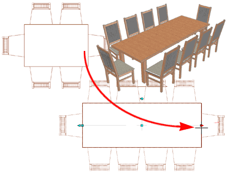
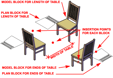
This solution employs a Curtain Wall Style where there will be a single chair at the Right and Left Ends and double opposing chairs along the Length. In order to get a custom Curtain Wall Style to create this type of solution, you will need to create some custom Blocks as illustrated to the right.
For the Ends, use a single Block for a 3D Model of the chair and a another Block for the 2D Plan of the same chair. In this example I named mine "chair_dininig_1_m" and "chair_dining_1_plan" respectively.
For the Length, use a single Block for the 3D Model of opposing chairs and another Block for the 2D Plan of the same opposing chairs. Curtain Walls don't have a front and back component option so this trick is used to overcome that problem. The drawback is that the width between the chairs becomes fixed by the anticipated width of the table top. In this example I am using 3'-6" (42") of space between the chairs and I named the blocks "chair_dining_1x2_m" and "chair_dining_1x2_plan" respectively.
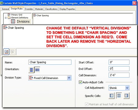
Create a New Curtain Wall Style and name it something like "I_Furn_Table_Dining_ Rectangular_42w". Under the Divisions section, change the name of the default "Vertical Divisions" to something like "Chair Spacing" and set the Cell Dimension to something like 2'-6" (30"). In this example I set the Cell Adjustment to "Shrink" for the Middle Cells but you may find that you will need to come back and tweak these settings as required for the results you seek in a specific case.
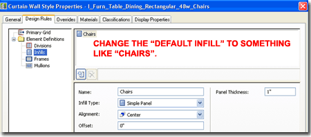
Under the Infills section, change the "Default Infill" name to something like "Chairs". Later I will show how to use this Infill as the double opposing chairs.
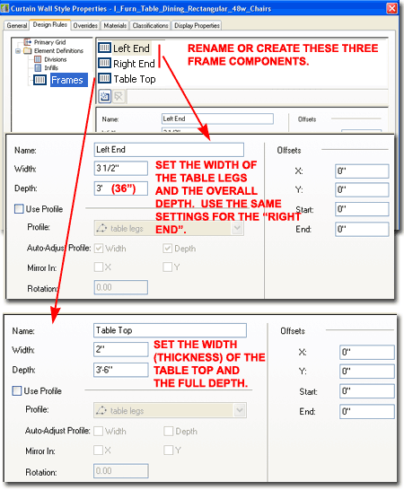
Under the Frames section rename the "Default Frame" to "Left End" and create two other Frame components: "Right End" and "Table Top".
For the Left End and Right End components, set the Width to the width you want for your table support\leg and set the Depth to the full depth you want for your support\legs. In the illustration to the right I show a Width of 3 1/2" and Depth of 3' (36") so this will produce a single rectangular support. If you want two rectangular or round legs, you can use a custom Profile as outlined below under Checking the results and making some improvements.
For the Table Top component, set the Width to the thickness of your table top and a Depth that now matches the distance you set between the double opposing chairs. For this example, I set my Table Top Width to 2" and the Depth to 3'-6" (42").
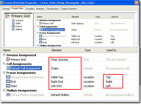
For the Primary Grid you can now use the "Chair Spacing" created earlier. For the Cell Assignment, use the "Chairs" Infill created earlier. For Frame Assignments, Add two new ones and then set one to "Table Top" (Used In "Top"), one to "Right End" (Used in "Right") and one to "Left End" (Used In "Left") as illustrated to the right.
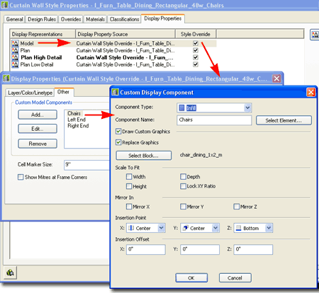
On the Display Properties tab of this custom Curtain Wall Style, you will need to use Style Overrides for all of the Display Representations because the Blocks you created earlier will now be Added.
In the illustration to the right I show that I have set a Style Override for the Model Display Representation and used the "Other" tab to Add... my "chair_dining_1x2_m" Block as a Replacement Graphic for the "Chairs" Infill. The Insertion Point has been set to "Center", "Center", "Bottom". This work has now replaced the default Infill with the Block of the 3D double opposing chairs.
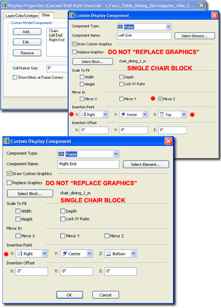
To Add... the chair Blocks to the table ends, you will need to add the same Block twice; once for each end.
In the illustration to the upper right, I show that I have Added the "chair_dining_1_m" Block to the Left End Frame Component (created earlier). Though this Block is a Custom Graphic it will not be a Replacement because that would remove the table support/leg. Curtain Walls have a goofy way of viewing the perimeter frame as circular so depending on the original orientation of the single chair Block, you will find that you have to Mirror one on the Z-axis and then flip the Z insertion point to Top.
In the lower right illustration, I show how the same "chair_dining_1_m" Block has been added to the Right End Frame Component and does not require the use of Mirror Z and can use the Bottom Z-axis insertion point.
If you don't know which of the two ends needs the Mirror Z setting, just pick one and when you look at the final work in 3D it will become very obvious which one may need to be changed.
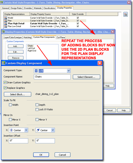
In the illustration to the right I show that I have added the 2D Plan Blocks to the Plan Display Representation Style Override exactly like I added the 3D Model Blocks in the discussion above. You will need to repeat these steps for each of the Display Representations that you wish to use in your drawings.
After you have completed the work outlined above you should check your work and see if the 3D assembly is coming together correctly. If you attempt to View your work from a Top or Plan View, you probably won't see anything because the Cut Planes have not been adjusted to fit the height of your table. I will address this matter later.
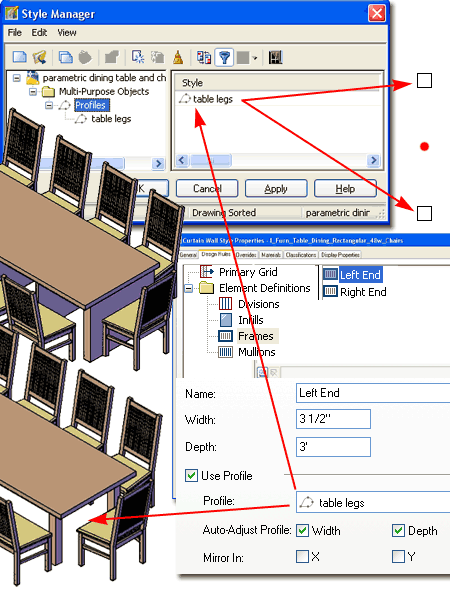
In the illustration to the right I show how you can use a Profile Definition based on two rectangles to create square or round table legs.
Note:
You may wish to remove the default mullion component since they are likely
to look like support components between each of the double opposing chairs.
To do this, simply go to the Mullions section of the Curtain Wall style and
set the Default Mullion values to zero (0).
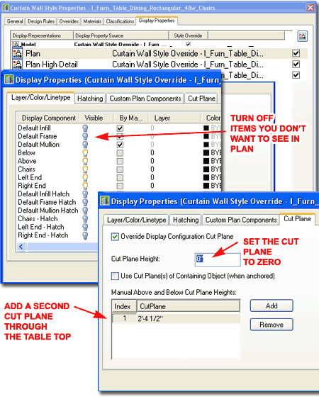
To complete the work on this custom parametric
table and chair object, go back to the Plan Display Representations for the
custom Curtain Wall Style and turn Off all Display Components
 you
don't want to see in Plan. On the Cut Plane tab, set the Cut Plane
Height to zero (0) and then Add a new Cut Plane that runs through the
anticipated table
top height. Repeat this work for each of the Plan Display Representations and
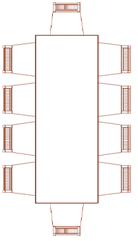
you should end up with Plan Views that look something like the illustration
to the left.
you
don't want to see in Plan. On the Cut Plane tab, set the Cut Plane
Height to zero (0) and then Add a new Cut Plane that runs through the
anticipated table
top height. Repeat this work for each of the Plan Display Representations and
you should end up with Plan Views that look something like the illustration
to the left.
Over the last couple of years I have received comments ranging from "this is just too much work" to "I simply can't follow all of what you wrote". This year I have added eParts to the list of ARCHIdigm's products so I can package solutions like this into smaller and hopefully more affordable groups. I plan to create more variations on this solution and include conference tables for a Furniture eParts product in the near future.
