If you work like me then you probably use every Object in ADT to do just about anything you can get out of it even if it was never meant to be used in that way. I recently did a whole complex Roof System in Mass Elements because the Roof was Arched Pre-cast Concrete and ADT doesn't have that RoofSlab Style. Though I could have converted my Mass Elements into RoofSlabs, I didn't see the need nor would that conversion have facilitated better results. The problem with using something like a Mass Element and Extruding it along the X or Y-axis is that you can't see it correctly in Plan View. Those of you who have become ardent fans of the Curtain Wall know exactly what I am talking about here.
The Problem is that the creators of the Objects in ADT had no idea that we would want a Plan View of any Object no matter how it was drawn relative to the X, Y or Z-axis so sometimes the only thing we see in Plan View is a line at the origin of our Object(s). For me, the biggest problem is that I need to see all Objects correctly in Plan View in order to design and align things properly and ADT does not offer a Display Configuration, by default, for this problem so in this article I'll discuss how to create your own "Model" Display Configuration.
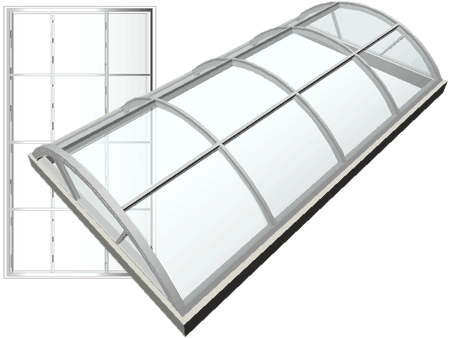
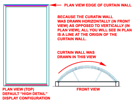
Illustrated to the right I show an example of how an arched skylight might have been created using a custom Curtain Wall Style. Since it was drawn in Front (Elevation) View, ADT will not display it correctly in true Plan View because as far as the Object is concerned, plan view is Front ( where it happens to look pretty good). In true Plan View, all that you will see is a line representing the Edge of the Curtain Wall - see illustration to the right. This scenario is true of most Objects in ADT that are drawn out of plane.
To assist in working with Objects that have this problem, you can create a New Display Configuration that displays full 3D Geometry in Plan View. Even if you don't tweak your ADT Objects as described here, it can be quite nice to have this Display Configuration to do things like Shading in Plan View to see Objects as 3D instead of 2D.
Illustrated to the right I show how you can create a new Display Configuration in seconds. All you have to do is highlight a known Display Configuration that you would like to use for Model, right-click over it, Select New off the pop-up menu and Rename the Copied Display Configuration to something like "Model High Detail" or simply "Model".
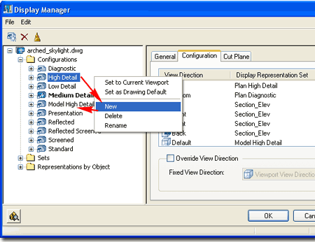
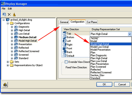
Continuing from the previous discussion above, highlight your New Display Configuration and look for the Configuration tab in the right pane of the Display Manager Window - as illustrated to the right. For the Top View Direction, use the Display Representation Set drop-down list to set one of the Model Display Representation Sets such as "Model High Detail".
By taking this action, you are forcing the Top (Plan) View to display all of the ADT Objects in Model form rather than 2D Plan form.
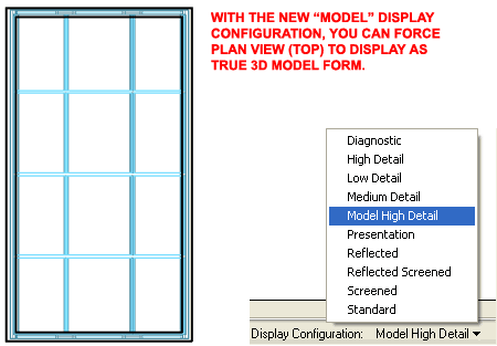
Once you have completed the creation of your own custom Display Configuration as outlined above, you should now be able to use it to change the current Display Configuration as illustrated to the right.
Notice that the Curtain Wall used to create the arched skylight now displays in a more acceptable fashion from the Top.
In Part 2 of this article I will discuss how to make this type of Display Modification to one or more Objects (instead of the whole project) so you can use this solution for your Construction Documents.
