As anyone knows who has attempted to create framing plans in Architectural Desktop, the tools just aren't there. Oh sure you have Structural Members and that wacky .XML Catalog but try creating a typical floor framing or roof framing plan with those objects and you will soon be uttering words that shouldn't be spoken out loud ( at least in public ).
The problem with the Structural Member objects is that the tools needed to make them viable solutions for framing don't exist and the internal dialog box settings that will do a lot of cool things take so long to understand and set that by the time you have one member set correctly, you could have Arrayed some Plines and be on to annotation work.
The irony is that for framing, a lot of the tools we need are actually there but for other objects and in this story we will take a look at how you can use Roof Slabs to create Roof Framing Plans in 2D and 3D.
Illustrated to the right I show the typical Add Roof Slab dialog box and some of the settings you might use to create a simple linear ridge beam. Though I show a Style named "Ridge Beam" it is not necessary to create a custom style and "Standard" will actually work just fine. The real key to using a Roof Slab as a framing member is to realize that you are simply creating a narrow roof.
On the Mode drop-down list, you will most likely want to draw the beam based on the Slope value so use the Projected mode and later we will set the Slope to zero.
On the Thickness value field set the desired member size.
On the Base Height value field do your best to estimate the actually height but since calculating exact ridge points usually requires a bit of geometry, you can just get close for now and move the beam later.
On the Overhang value field decide on the need for an overhang. If you do set an overhang, then draw the beam at the plate and even if you don't, you can Stretch the Beam later.
On the Justify drop-down list, simply choose where you want the Base Height measured to in relationship to the beam ( Bottom often makes sense ).
On the Slope value fields, you will want an Angle of zero in most cases
When you are ready to start the first point of your Ridge Beam, pick a spot on the Wall and draw in the direction of the width of the beam ( see Step 2 ). Type in the Width for your Ridge Beam and then draw in the direction of the span ( see Step 3 ). Now, continue around as if drawing a Pline rectangle and Close for the last leg.
If you used the Overhang setting on the Add Roof Slab dialog box, you would see it protrude out beyond the first two points. Remember that you can Move and Stretch the Roof Slab much like any other object so adjustments should be fairly easy. The only word of caution I have is that you can accidentally affect the 3D structure of a Roof Slab by
Osnapping to incorrect points and thus alter the object in undesirable ways. If you get concerned about any modifications, just check the results in an Isometric View before moving on. One really obvious indication of a problem is when you see an extra line at either end because that usually means the beam is tilted and you can actually see across the end while in Plan ( not good ).
To create common Rafters, the work is basically identical to the Ridge Beam with the exception of a Slope.
Illustrated to the right I show the Add Roof Slab dialog box set to create a simple common rafter at a slope of 4 and 12 at a Plate (Base Height) height of 9'-0".
As with the Ridge Beam, I show a unique Style name and with Rafters, I find it more beneficial to create a unique Style than with the Ridge Beam. This is because with Rafters I often adjust the Offset Values so I can get the Rafter to connect to my Top Plate right where it should and not how
ADT does it by default ( to the outside - huh? ). Since this article isn't about Roof Slab Styles and Properties, I show the default method below right but you can read all about Roof Slabs in our Architectural Desktop 3 Development eGuide.
Using the same technique described for the Ridge Beam, draw the Rafter by starting at the point where you want the Pivot Point for the Slope and then draw in the direction of the Width so you can type in the width of the Framing Member.
Don't worry about the cut at the ridge beam since this can be adjusted later - as you may notice it may come out Square cut by default.
Note:
In the illustration to the right, I show the pivot point at the exterior of the wall plate
for simplicity. Using a unique Roof Slab Style designed to be used
as a Rafter, you can use Offsets to adjust where you may want to locate
the Rafter relative to the plate; i.e, draw along the inside of the wall plate where the
rater actually hits. You can, of course, also simply move the rafter in Elevation
View after creating it.
One of the best things about using Roof Slabs for Roof Framing has to do with all the great tools for Modifying them. Roof Slabs can be Cut, Mitered, Trimmed, Extended, Booleaned and so on so there should be plenty of options to achieve the results you seek.
Illustrated to the right I show how Grip Stretching in Plan can be used to quickly make a Rafter longer or shorter without messing with the Pitch - be careful about Osnapping to points in space though.
Also Illustrated to the right I show how you can use the RoofSlabTrim command in combination with a common Pline to Trim a Rafter when it doesn't want to trim to another Roof Slab the way you think it should. You should definitely try to the other modification tools like Cut and Miter to achieve similar results.
As I stated in the opening to this article, I don't find that the Structural Members are well suited for creating Framing Plans and thus this prompted me to seek a better and more expedient solution. The price for this alternative is that I don't reap the benefits of using "Structural Members" and the data associated with them but then I usually don't tag my Rafters or Joists so the price was next to nothing.
One of the best benefits of using Roof Slabs and Slabs for framing is that you can use the simple Editing tools to Cut, Trim, Miter and even Boolean them as you see fit. By having the Fascia setting as a Property, you can adjust the member ends without all of the convoluted complexity of the Structural Member Trim Planes.
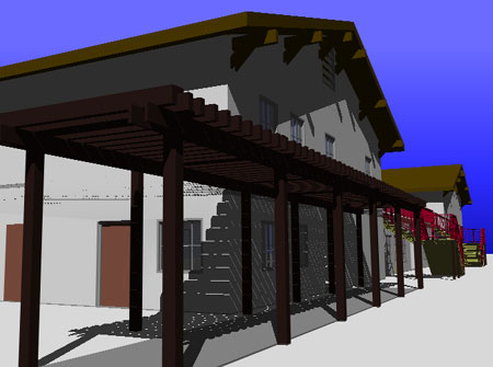
Illustration to the right:
Exposed Rafters and Ridge Beam created with Roof Slabs. 2x Roof Decking created with
a common Roof objects. Screened openings created with a Window Assembly
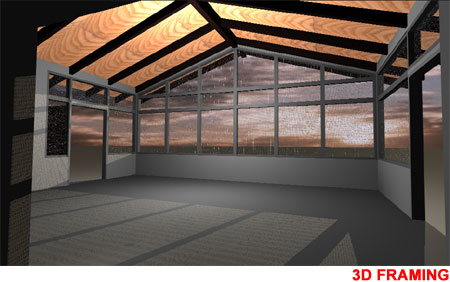
Trellis and Knee Braces created with Roof Slabs. Trellis Columns were created with the Slab object.