If you have been working with Architectural Desktop and struggled to create more sophisticated Door and Window combinations, what you need to work with are the Window Assembly Styles. The unfortunate aspect of the Window Assembly Style is that it just plain scares most users when they see it the first time and thus many never bother to return and master this beast.
In the discussion below you will be guided through some basic steps and hopefully well on your way to becoming the Window Assembly Master.
Be aware that there are numerous methods for working with the Window Assembly Styles and that the discussion and examples below are meant to get you going faster. Later, you should investicate other methods for creating Window Assembly Styles.
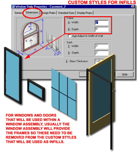
One of the first mistakes most users make when trying to create custom Window Assembly Styles is to use the standard Door and Window Styles for Infills. This is actually okay but in most cases, the frame of the Assembly contains the Door and/or Window and thus there is no need for a second Frame.
Illustrated to the right I show how you can remove the Frames for Window and Door Styles. Make sure that you Create a New Door or Window Style so you don't do this to your regular Door and Window Styles. You can also remove the Sash or Jamb if you wish by simply using a 0" dimension for Width and Depth.
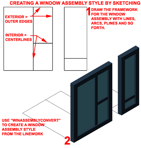
One of the easiest methods for creating a custom Window Assembly Style that architects really seem to comprehend is the sketch technique illustrated to the right.
When you draw your Window Assembly Frame System, remember that the exterior lines actually represent the exterior Frame edge while the interior lines represent the centerlines of Mullions. You can use Lines, Plines, Arc and even Circles to create the sketch.
Once you have a frame and mullion sketch, use the "WinAssemblyConvert" command, also accessed via the Openings toolbar and the Design Pull-down menu, to Select all of your linework. To finish the conversion, simply use all of the default options for completion and you should find a 3D Window Assembly standing upright from the bottom line of your linework - as illustrated to the right.
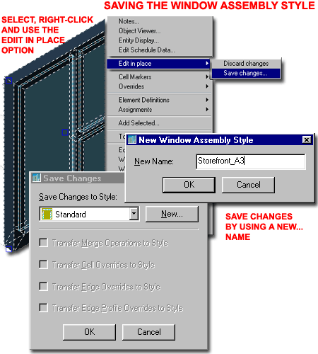
When you Convert Linework to a Window Assembly, the Standard Window Assembly Style is used to generate a default solution for you. In addition to using the Standard Style, ADT puts you in an "Edit in Place" mode that allows further editing prior to Saving to a Window Assembly Style Name. Though this is a great option, it's is best to Save this Style now so you don't forget that you are in "Edit in Place" mode.
To Save, Select the Window Assembly, right-click on your mouse, cascade to Save changes... via the Edit in place cascading menu option on the object-specific pop-up menu - as illustrated to the right.
On the Save Changes dialog box, use the New... button and specify a name that defines how you want your Window Assembly listed in your Schedule ( if you plan on having it in your Schedule, otherwise use any name you want ).
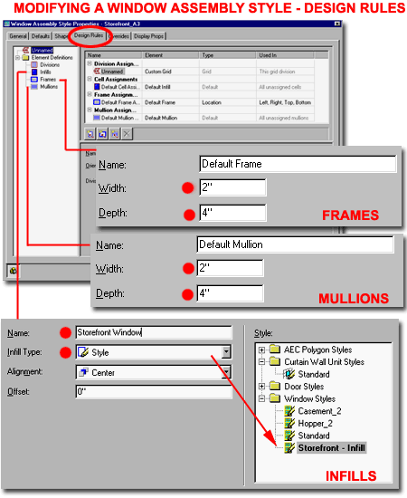
Once you have saved the custom Window Assembly Style, created above, you can modify the Style as you would any object style in ADT.
Illustrated on the right I show the Design Rules tab of the Window Assembly Style Properties dialog box. Under this tab, change the dimension of the Default Frames and Mullions to match your design needs.
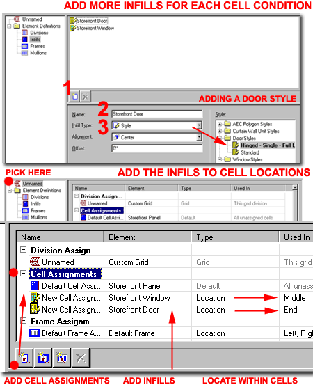
On the Infills portion of the Element Definitions, specify a Name that indicates the object style you intend to stick inside one or more of the Window Assembly Cells. On the Infill Type drop-down list, select Style so that you can access any of the Door and Window Styles in the right-hand Style Pane.
Illustrated to the right I show that I am currently in the process of adding a custom Wndow Style that I called "Storefront - Infill" ( created earlier ). I have also named this Infill so I can keep track of it as I add other Infills.
Use the Add Infill button ( 1 ) to create a new infill and repeat the steps outlined above. You can add all sorts of infills even if you don't intend to use them in the current Window Assembly Style. By having Infill options, you can actually go back later via the Edit in Place mode and pop in other Infills to create unique versions of the current Window Assembly Style - these would either be considered overrides or could be saved as new Window Assembly Styles.
If you plan on having a simple Panel in your design, Add an Infill that does not use a Style but simply uses the Simple Panel Infill Type. For the Panel, you can specify the Width to be something like a Wall, Woor or Metal Panel or Solid Frame section.
Note:
Though you can have numerous Panel Infills, you can only have one Color for all of these
Panels and that really limits the presentation options - I hope this is fixed in ADT 4.
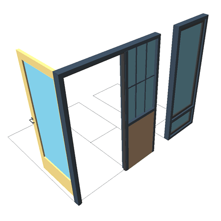
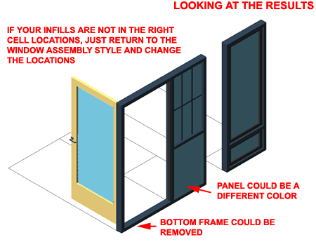
Illustrated to the right I show two different Custom Window Assembly Styles created with this techique; one is a simple storefront unit and the other is a Casement and Hopper/Fixed combination Window.
Once your review your work, you may start to observe things that would like to change.
Illustrated to the right I indicate how the storefront example has a frame element at the bottom. This might be desirable in the panel section but is usually not desirable under the door. Now here is the big irritant, if you try to keep the frame in the panel section, it affect the position of the door and thus the door will sit as if there is still a frame under it. In other words, it's best to remove the frame altogether for now. If this is a huge problem for you needs, you can tinker with an infill or Add custom linework via the Block method. I have messed with many options and finally resolved to adding the final linework on my elevations and sections with AutoCAD.
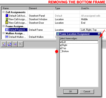
To remove the Bottom Frame of the Custom Window Assembly, simply return to the Window Assembly Properties dialog box and go to the Design Rules tab.
For Frame Assignments, pick in the Used In cell of the "Default Frame Assignement" row to see the dot-dot-dot button that will activate the Frame Location Assignment dialog box illustrated to the right.
On the Frame Location Assignment dialog box, simply uncheck any frame positions that you don't want the current Frame in.
By the way, this is also how you can use different Frame Dimensions for different parts of your Custom Window Assembly. I have used this option to create a very small Frame Height that I use for a threshold on exterior Window Aseembly Units with Doors in them.
Though it may not be significant for anything other than your state of mind or to add pizzaz to the presentation, you can change the Color of the Simple Panel. As mentioned above, however, you only have one Color option for all of the Simple Panels so you cannot have different colors.
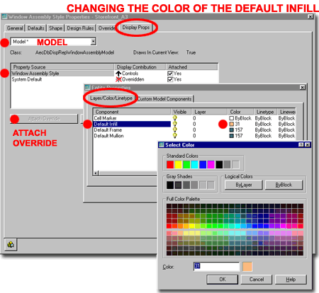
Illustrated to the right I show how you can use the Display Props tab of the Window Assembly Style Properties dialog box to Attach an b for the Model Display Representation of your custom Window Assembly Style. Once you have Attached an Override, you can edit the Entity Properties and change the Color of the Default Infill on the Layer/Color/Linetype tab.
Why Attach an Override?
If you don't use the Attach Override option, you will be changing the Color of All Default
Infills in All of the Window Assembly Styles of the current drawing file. That's
would not be good because the most common use of the Default Infill is to represent Glass
( Color 141 ).
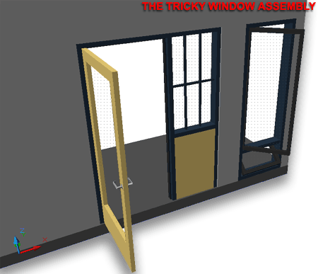
Once you have completed tweaking your Custom Window Assembly Style, the final product should prove to be a lot better than trying to stick Doors right next to Windows or trying to stick several windows right next to each other by overlapping jambs.
For information on using Door and Window Tags with Window Assemblies, you can read up on Schedules and Tags in our subscription based Architectural Desktop 3 Development eGuide.