Ordinarily trim on Doors and Windows in Architectural Desktop would not be a significant issue for me to complain about but Renderings have pushed this matter to the forefront. Door and Window trim makes a huge difference in the appearance of exterior elevations and I find basic detailing like this can contribute a lot to the communication process with clients in early Design and Development phase.
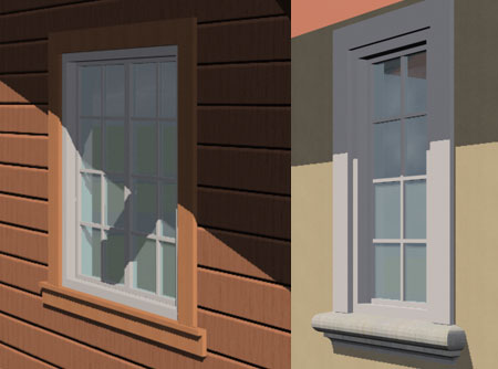
I don't believe that I am asking for much especially since I don't even care if the components reflect true construction. While I wait for improvements I will pass on a couple of tricks I have been employing to create the types of images to the right.
Door and Window Styles provide options for attaching Blocks so if you are clever and patient you may be able to add trim to these Objects directly. Door/Window Assembly Styles (basically Curtain Wall Styles with the option to Anchor in Walls) provide options for setting a unique Profile shape to any single or all sides of an opening. As you might expect, whenever you attempt to create custom solutions, there are advantages and disadvantages to adding trim on the Primary Object Style or on an Assembly Style. Below I will run through the basic steps for both options.
For Door and Window Objects you can Add Blocks to represent trim and the first step is to create the trim in 3D. Illustrated to the right I show an example Door from the Default Library in ADT and the three Mass Element Boxes I plan to use for trim on this Object.
Now that Mass Elements have their own Styles they are pretty good for work like this but I suppose you could use other Objects in ADT if you prefer. The reason I need three separate pieces will become self-evident when I get to the options for scaling these attachments.
When you are ready to make the Blocks for each trim piece, make sure to have the UCS set to World so the orientation of the Block will match that of the Door. In the illustration to the right I show the Base Points I chose for this example but you may find that other points make more sense to you.
If you plan to use different trim on the inside and outside of the Door, you will need to create a similar set of pieces and follow the same instructions as outlined below.
One of my peeves about ADT is its uncanny requirement for repetitious labor in custom configurations. Making the trim pieces and Blocking them, as discussed above, is quite easy but now the real labor comes when you have to Add... these Blocks repetitively for each Display Representation in which you want to see them.
Illustrated to the right I show that I have set Display Style Overrides for "Elevation", "Model", "Model High Detail" and "Plan High Detail" (see comments three cells down). For each of these Display Representations, I used the Other tab to Add... my trim Blocks to the Right, Left, Top, Right Top Corner and Left Top Corner. I also added the same Blocks to the opposite side of the Door Style so the total number of Blocks Added equals 10. I repeated this crazy amount of work for the Elevation and Model High Detail Display Representations but only added the Right and Left trim Blocks to the Plan High Detail Display Representation because that is all that I want to see in Plan.
For each trim Block that you Add, you will need to review all of the settings on the Custom Block dialog. In the illustration to the right I show that I have set my "door_trim_edge" Block to automatically Scale to whatever Height the Door might be. When you use this option, the Height matches that of the Door and thus will not extend up beyond its frame to join with the trim above the Door; hence the need for the corner trim Block.
My Base Point for the edge trim Block was in the Lower Right inside corner and thus this should work well with the Left, Front, Bottom Insertion Point specification illustrated to the right. In this example I want my trim to flush up against the outside edge of the Door's Frame so I set the Frame Component to "Inside".
Though my edge trim Block worked for the Left side of my Door, I still have the right side and both of the opposite sides to deal with.
Illustrated to the right I show how I used the same "door_trim_edge" Block from the discussion above, to solve the need for trim on the Right side of the Door. I used the Mirror X option to flip the Block and set the X-Insertion Point to Right. Now that the trim Block is flipped, I had to compensate for the displacement by using the X-Insertion Offset value which I set to the width of the trim Block (-4").
The corner trim Blocks should not be Scaled because they will automatically move as the Width and/or Height of the Door changes.
The top trim Block should be Scaled to Width but not Height because it needs to stretch to match any changes in the Door's Width. The X-Insertion Point should be set to Center and the Z-Insertion Point should be set to Top.
After some trial and error runs you should soon figure out how you want to modify or adjust the basic work I have outlined here.
In the illustrations to the right I show some things you may want to consider. Under the "Plan High Detail" Display Representation I decided to Add the Right and Left trim Blocks so I could take advantage of the extra detail. By working with the Display Overrides for the Mass Element Style you should use for your custom trim Blocks, you can control the Color, Hatch and Lineweight of the trim.
It is unfortunate that those corner trim Blocks are needed but believe me, they are. The good news is that if the trim is one material, as it typically is, no one will see the extra lines in Renderings and you can even remove the extra lines in 2D Sections and Elevations - see comment below for how to do this.
If you followed my advice and created a unique Mass Element Style for your trim Blocks, you will now be able to set unique Display Style Overrides for the Material assigned to these Mass Elements. In the illustration to the right I show how you can check the "Merge Common Materials" setting on the Other tab of the current Display Representation of the Material used as trim. This single change will remove the extra linework in those automatically generated 2D Sections and Elevations in ADT. You may have to repeat the act of setting the "Merge Common Materials" for other Display Representations.
When you work with Door/Window Assembly Styles, you are actually working with a derivative of the Curtain Wall Style and as such, you have the option to work with each Frame Side individually. Frames, by default, are simple rectangles that are typically observed as Jambs and Sills but you can specify your own Profile shapes to make these components more complex. The benefit of using Door/Window Assembly Styles as a solution for adding Trim is that Lengths and Heights are a bit more flexible, Profiles can be switched very quickly and the general linework in 2D Elevations is often cleaner.
Illustrated to the right I show a very simple edge trim Profile that I will use for the sides and top of my example Window Assembly and a more complicated sill trim Profile for the bottom. If you decide to experiment with this technique, keep in mind that I am focusing more on the steps than how you may actually want to detail Doors or Windows in your office.
Though you can use a variety of strategies for managing the placement of custom Profiles, I have found that using the exact centroid (or something close) usually provides the best results because of how you can position the Profile within the Door/Window Assembly Style. I will elaborate on this subject below but notice how I have purposely used a different centroid for the Sill Profile, right, than the exact one.
The Width of the Trim should match the Wall you intend to place the Door/Window Assembly in but I will discuss options for variable Width Walls below.
Hindsight:
After completing this article I reviewed the choice for the insertion point
I show above on the sill and realized that a more carefully calculated point
would have kept me from needing to use a Y-Offset value - see example 2
cells down.
Within your Door/Window Assembly Style dialog go to the Frames section and define how you want your "Standard Trim" configured.
In the illustration to the right I show that I renamed the "Default Frame" to "Standard Trim" and set the Width and Depth value to match the outer rectangular dimensions of my Trim Profile created in the step discussed above. This is how the centroid Insertion Point will match the centroid of the rectangle specified by the Width and Depth.
Under the "Use Profile" settings, Select the Profile Name you use for the Standard Trim. If you set the Width and Depth values correctly, you can use the Auto-Adjust Profile "Width" and "Depth" without any change to the outcome. However, if you change the Width value be aware that this will also change the centroid position and you may have to use Offsets to counter this shift. When you Auto-Adjust Profiles, the Profile shape is scaled equally and thus some changes in trim thickness may become undesirable but you should find that you can use this to meet the needs for a common variety of wall thicknesses.
If you use a U-shaped Profile, as per my example, in place of the typical Door/Window Assembly Frame, you should find that ADT treats the shape as if it is a solid rectangular Jamb. To push the U-shaped Profile back into the Wall to match how you would trim a Window, use the "X" Offset value setting as illustrated to the right. In this example my total width is 3 1/2" but I have Offset the Profile by 3" to allow 1/2" of trim to wrap the face of the Wall Opening.
If you want something different for your Window Sill, you will need to create a New Frame Definition that will be assigned in the discussion below.
Illustrated to the right I show that I created a New Frame Definition that I named "Window Sill". Because I am trying to do something a little fancy with this example I show a way to fool ADT into allowing Frame components to intersect. Instead of using the overall dimensions of my Profile Shape, I am only specifying the rectangular dimensions for the sill components below the stool. If you refer back to my illustration of the Profile and the centroid I used for it, you will see how these now match. In essence, I don't want ADT to know about the stool because I want it higher than the bottom of the adjacent Trim components so that they connect properly with the lower sill at the front of the Window.
Under the "Use Profile" settings, Select the Profile Name you used for the Sill. For this unique example I will not use the Auto-Adjust Profile "Width" option because that will conflict with the stool trick I will address next.
 Under
the "Offset" settings, notice that I show an X value that
moves the Sill Profile up 1/2" relative to the Width Dimension; similar to
what I did for the "Standard Trim". Because the actual Profile shape
is Wider, this X-Offset allows my stool to be a full 1" higher than the
rough opening. The key for me on this trick was to keep the side trim
low enough to align with the outside sill (it slopes so I'm not perfect here
but pretty close).
Under
the "Offset" settings, notice that I show an X value that
moves the Sill Profile up 1/2" relative to the Width Dimension; similar to
what I did for the "Standard Trim". Because the actual Profile shape
is Wider, this X-Offset allows my stool to be a full 1" higher than the
rough opening. The key for me on this trick was to keep the side trim
low enough to align with the outside sill (it slopes so I'm not perfect here
but pretty close).
You may need to use the Y-Offset value to properly align your sill with your wall.
The use of the Start and End Offset values will allow you to run you Sill past the side trim. Use negative values if you want to create the effect illustrated left.
 The End
Once you have your Frame definitions configured, you can now Assign them for the Primary Grid as illustrated to the right. All you have to do is use the "New Frame Assignment" button, set the Frame Definition Names and use the "Used In" column to access the "Frame Assignment Location" dialog to set the locations.
This technique can be used for Doors as well and is pretty useful for Entry Doors with Sidelights, Transoms and so forth.